Site logo
Electrical Engineering Academy
A

Star-Delta Starter

STAR-DELTA STARTER

INTRODUCTION:

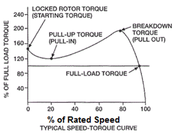
Most induction motors are started directly on line, but when very large motors are started that way, they cause a disturbance of voltage on the supply lines due to large starting current surges. To limit the starting current surge, large induction motors are started at reduced voltage and then have full supply voltage reconnected when they run up to near rotated speed. Two methods are used for reduction of starting voltage are star delta starting and auto transformer stating.

WORKING PRINCIPAL OF STAR-DELTA STARTER:

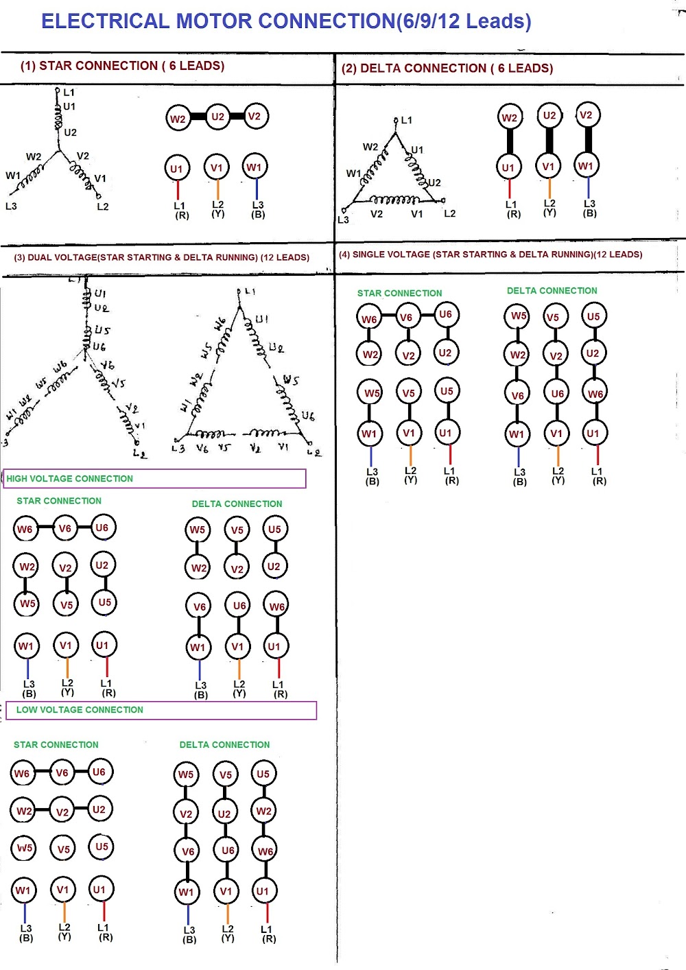
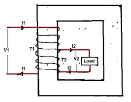
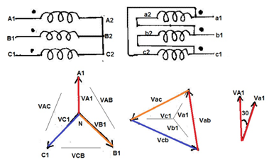
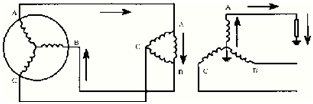
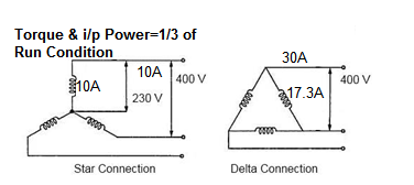
  • This is the reduced voltage starting method. Voltage reduction during star-delta starting is achieved by physically reconfiguring the motor windings as illustrated in the figure below. During starting the motor windings are connected in star configuration and this reduces the voltage across each winding 3. This also reduces the torque by a factor of three. After a period of time the winding are reconfigured as delta and the motor runs normally.

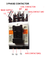
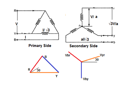
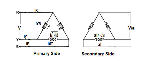
  • Star/Delta starters are probably the most common reduced voltage starters. They are used in an attempt to reduce the start current applied to the motor during start as a means of reducing the disturbances and interference on the electrical supply. * Traditionally in many supply regions, there has been a requirement to fit a reduced voltage starter on all motors greater than 5HP (4KW). The Star/Delta (or Wye/Delta) starter is one of the lowest cost electromechanical reduced voltage starters that can be applied. * The Star/Delta starter is manufactured from three contactors, a timer and a thermal overload. The contactors are smaller than the single contactor used in a Direct on Line starter as they are controlling winding currents only. The currents through the winding are 1/root 3 (58%) of the current in the line. * There are two contactors that are close during run, often referred to as the main contractor and the delta contactor. These are AC3 rated at 58% of the current rating of the motor. The third contactor is the star contactor and that only carries star current while the motor is connected in star. The current in star is one third of the current in delta, so this contactor can be AC3 rated at one third (33%) of the motor rating.

STAR-DELTA STARTER CONSISTS FOLLOWING UNITS:

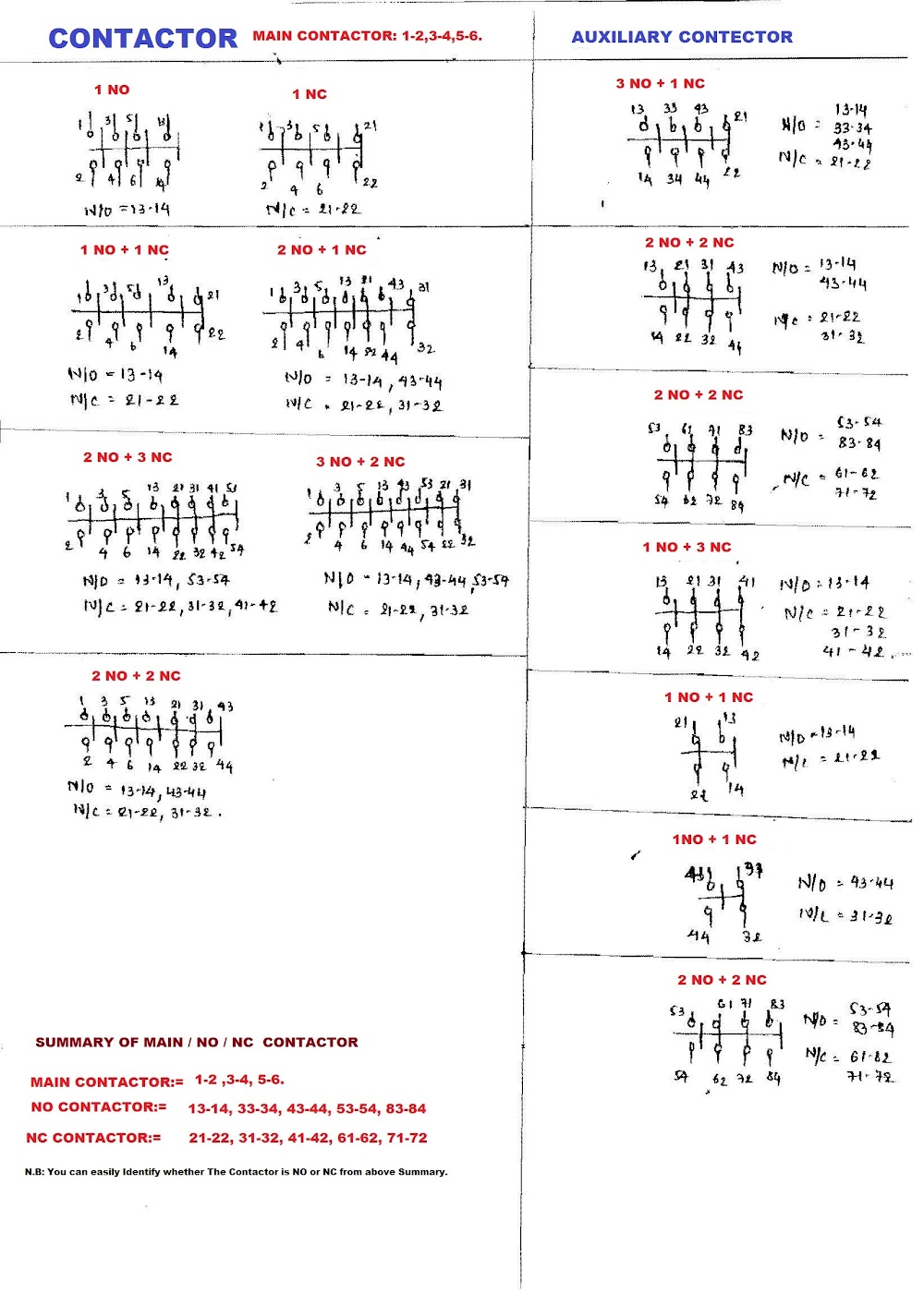
  1. Contactors (Main, star and delta contactors) 3 No’s (For Open State Starter) or 4 No’s (Close Transient Starter).

  2. Time relay (pull-in delayed) 1 No.

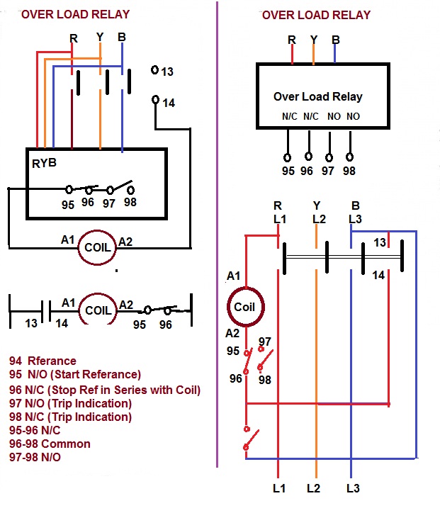
  3. Three-pole thermal over current release 1No.

  4. Fuse elements or automatic cut-outs for the main circuit 3 Nos.

  5. Fuse element or automatic cut-out for the control circuit 1No.

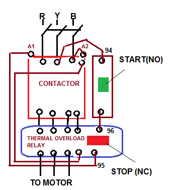
POWER CIRCUIT OF STAR DELTA STARTER:

  • The main circuit breaker serves as the main power supply switch that supplies electricity to the power circuit. * The main contactor connects the reference source voltage R, Y, B to the primary terminal of the motor U1, V1, W1. * In operation, the Main Contactor (KM3) and the Star Contactor (KM1) are closed initially, and then after a period of time, the star contactor is opened, and then the delta contactor (KM2) is closed. The control of the contactors is by the timer (K1T) built into the starter. The Star and Delta are electrically interlocked and preferably mechanically interlocked as well. In effect, there are four states:

Y-D

  • The star contactor serves to initially short the secondary terminal of the motor U2, V2, W2 for the start sequence during the initial run of the motor from standstill. This provides one third of DOL current to the motor, thus reducing the high inrush current inherent with large capacity motors at startup. * Controlling the interchanging star connection and delta connection of an AC induction motor is achieved by means of a star delta or wye delta control circuit. The control circuit consists of push button switches, auxiliary contacts and a timer.

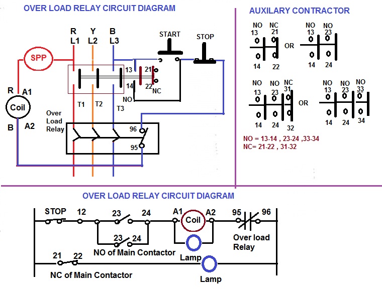
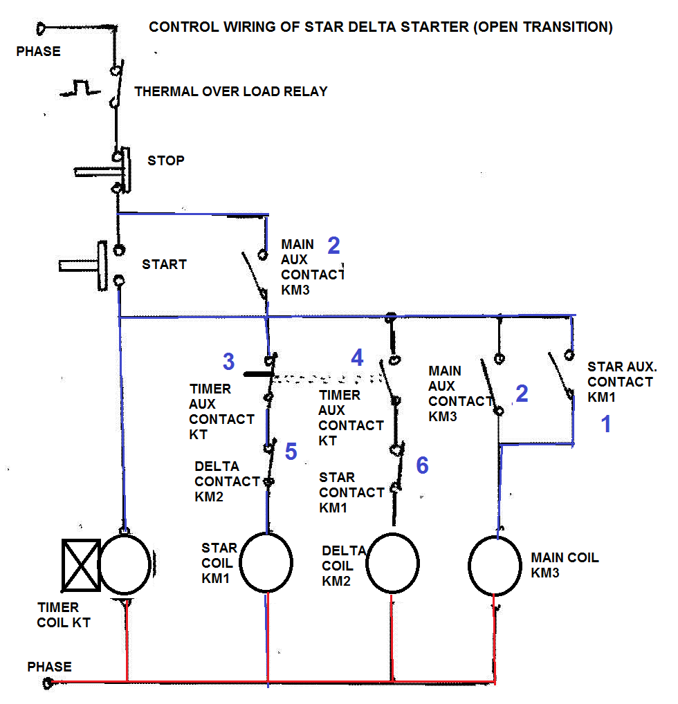
CONTROL CIRCUIT OF STAR-DELTA STARTER (OPEN TRANSITION):

  • The ON push button starts the circuit by initially energizing Star Contactor Coil (KM1) of star circuit and Timer Coil (KT) circuit. * When Star Contactor Coil (KM1) energized, Star Main and Auxiliary contactor change its position from NO to NC. * When Star Auxiliary Contactor (1)( which is placed on Main Contactor coil circuit )became NO to NC it’s complete The Circuit of Main contactor Coil (KM3) so Main Contactor Coil energized and Main Contactor’s Main and Auxiliary Contactor Change its Position from NO To NC. This sequence happens in a friction of time. * After pushing the ON push button switch, the auxiliary contact of the main contactor coil (2) which is connected in parallel across the ON push butto…
A

Direct On Line Starter

DIRECT ON LINE STARTER

INTRODUCTION:

  • Different starting methods are employed for starting induction motors because Induction Motor draws more starting current during starting. To prevent damage to the windings due to the high starting current flow, we employ different types of starters. * The simplest form of motor starter for the induction motor is the Direct On Line starter. The DOL starter consist a MCCB or Circuit Breaker, Contactor and an overload relay for protection. Electromagnetic contactor which can be opened by the thermal overload relay under fault conditions. * Typically, the contactor will be controlled by separate start and stop buttons, and an auxiliary contact on the contactor is used, across the start button, as a hold in contact. I.e. the contactor is electrically latched closed while the motor is operating.

PRINCIPLE OF DOL:

  • To start, the contactor is closed, applying full line voltage to the motor windings. The motor will draw a very high inrush current for a very short time, the magnetic field in the iron, and then the current will be limited to the Locked Rotor Current of the motor. The motor will develop Locked Rotor Torque and begin to accelerate towards full speed. * As the motor accelerates, the current will begin to drop, but will not drop significantly until the motor is at a high speed, typically about 85% of synchronous speed. The actual starting current curve is a function of the motor design, and the terminal voltage, and is totally independent of the motor load. * The motor load will affect the time taken for the motor to accelerate to full speed and therefore the duration of the high starting current, but not the magnitude of the starting current. * Provided the torque developed by the motor exceeds the load torque at all speeds during the start cycle, the motor will reach full speed. If the torque delivered by the motor is less than the torque of the load at any speed during the start cycle, the motor will stops accelerating. If the starting torque with a DOL starter is insufficient for the load, the motor must be replaced with a motor which can develop a higher starting torque. * The acceleration torque is the torque developed by the motor minus the load torque, and will change as the motor accelerates due to the motor speed torque curve and the load speed torque curve. The start time is dependent on the acceleration torque and the load inertia. * DOL starting have a maximum start current and maximum start torque. This may cause an electrical problem with the supply, or it may cause a mechanical problem with the driven load. So this will be inconvenient for the users of the supply line, always experience a voltage drop when starting a motor. But if this motor is not a high power one it does not affect much.

PARTS OF DOL STARTERS:

(1) Contactors & Coil.

  • Magnetic contactors are electromagnetically operated switches that provide a safe and convenient means for connecting and interrupting branch circuits. * Magnetic motor controllers use electromagnetic energy for closing switches. The electromagnet consists of a coil of wire placed on an iron core. When a current flow through the coil, the iron of the magnet becomes magnetized, attracting an iron bar called the armature. An interruption of the current flow through the coil of wire causes the armature to drop out due to the presence of an air gap in the magnetic circuit.

  • Line-voltage magnetic motor starters are electromechanical devices that provide a safe, convenient, and economical means of starting and stopping motors, and have the advantage of being controlled remotely. The great bulk of motor controllers sold are of this type. * Contactors are mainly used to control machinery which uses electric motors. It consists of a coil which connects to a voltage source. Very often for Single phase Motors, 230V coils are used and for three phase motors, 415V coils are used. The contactor has three main NO contacts and lesser power rated contacts named as Auxiliary Contacts [NO and NC] used for the control circuit. A contact is conducting metal parts which completes or interrupt an electrical circuit. * NO-normally open * NC-normally closed

(2) Over Load Relay (Overload protection).

  • Overload protection for an electric motor is necessary to prevent burnout and to ensure maximum operating life. * Under any condition of overload, a motor draws excessive current that causes overheating. Since motor winding insulation deteriorates due to overheating, there are established limits on motor operating temperatures to protect a motor from overheating. Overload relays are employed on a motor control to limit the amount of current drawn. * The overload relay does not provide short circuit protection. This is the function of over current protective e…
Cover image
A

Motor Name Plate Terminology

MOTOR NAME PLATE TERMINOLOGY

GENERAL TERMINOLOGY

(1) SERVICE FACTOR:

  • The service factor is a multiplier that indicates the amount of overload a motor can be expected to handle. If a motor with a 1.15 service factor can be expected to safely handle intermittent loads amounting to 15% beyond its nameplate horsepower. * For example, many motors will have a service factor of 1.15, meaning that the motor can handle a 15% overload. The service factor amperage is the amount of current that the motor will draw under the service factor load condition.

(2) SLIP:

  • Slip is used in two forms. One is the slip RPM which is the difference between the synchronous speed and the full load speed. When this slip RPM is expressed as a percentage of the synchronous speed, then it is called percent slip or just “slip”. Most standard motors run with a full load slip of 2% to 5%.

(3) SYNCHRONOUS SPEED:

  • This is the speed at which the magnetic field within the motor is rotating. It is also approximately the speed that the motor will run under no load conditions. For example, a 4 pole motor running on 60 cycles would have a magnetic field speed of 1800 RPM. The no load speed of that motor shaft would be very close to 1800, probably 1798 or 1799 RPM. The full load speed of the same motor might be 1745 RPM. The difference between the synchronous speed and the full load speed is called the slip RPM of the motor.

Untitled

MOTOR TORQUE:

(1) PULL UP TORQUE:

  • When the motor starts and begins to accelerate the torque in generally decrease until it reach a low point at a certain speed it called the pull-up torque. * The Pull-up Torque is the minimum torque developed by the electrical motor when it runs from zero to full-load speed (before it reaches the break-down torque point). * Pull-up torque is the minimum torque developed during the period of acceleration from locked-rotor to the speed at which breakdown torque occurs. * Some motor designs do not have a value of pull up torque because the lowest point may occur at the locked rotor point. In this case, pull up torque is the same as locked rotor torque. * For motors which do not have a definite breakdown torque (such as NEMA design D) pull-up torque is the minimum torque developed up to rated full-load speed. It is usually expressed as a percentage of full-load torque.

(2) STARTING TORQUE (LOCKED ROTOR TORQUE):

  • The amount of torque the motor produces when it is energized at full voltage and with the shaft locked in place is called starting torque. * The Locked Rotor Torque or Starting Torque is the torque the electrical motor develop when its starts at rest or zero speed. * It is the amount of torque available when power is applied to break the load away and start accelerating it up to speed. * A high Starting Torque is more important for application or machines hard to start – as positive displacement pumps, cranes etc. A lower Starting Torque can be accepted in applications as centrifugal fans or a pump where the start loads is low or close to zero.

 (3) FULL LOAD TORQUE:

  • Full load torque is the rated continuous torque that the motor can support without overheating within its time rating. * In imperial units the Full-load Torque can be expressed as * T full-load torque (lb ft) = (Rated horsepower of Motor X 5252) / Rated rotational speed (rpm) * In metric units the rated torque can be expressed as * Full-load torque (Nm) = (Rated KW of Motor X 9550) / Rated rotational speed (rpm) * Example :The torque of a 60 hp motor rotating at 1725 rpm can be expressed as * T full-load torque = 60 X 5,252 / 1725 (rpm) * T full-load torque = 182.7 lb ft

(4) PEAK TORQUE:

  • Many types of loads such as reciprocating compressors have cycling torques where the amount of torque required varies depending on the position of the machine. * The actual maximum torque requirement at any point is called the peak torque requirement. * Peak torques is involved in things such as punch presses and other types of loads where an oscillating torque requirement occurs.

(5) PULL OUT TORQUE (BREAKDOWN TORQUE):

  • Breakdown torque is the maximum torque the motor will develop with rated voltage applied at rated frequency without an abrupt drop in speed. Breakdown torque is usually expressed as a percentage of full-load torque * The load is then increased until the maximum point is reached.

MOTOR CURRENT:

(1) FULL LOAD AMPS:

  • The amount of current the motor can be expected to draw under full load (torque) conditions is called Full Load Amps. It is also known as nameplate amps.

(2) LOCKED ROTOR AMPS:

  • Also known as starting inrush, this is the amount of current the motor can be expected to draw under starting conditions when full voltage is applied. * Lock Rotor Current (IL) Three Phase Motor: 1000x HP x (KVA/H…
A

4. Overload Relay Size & Contactor for Starter

OVER LOAD RELAY & CONTACTOR FOR STARTER

OVER LOAD RELAY & CONTACTOR FOR MOTOR STARTER:

TYPES OF OVER LOAD RELAY:

  1. Class 10: Would Trip after 10 seconds. 2. Class 20: Would Trip after 20 seconds. 3. Class 30: Would Trip after 30 seconds.
  • Over Load Relay should be set 115% to 130% of Motor Full Load Current. * Class 10 is faster than Class 20 and Class 30 over Load Relay.

SIZE OF OVER LOAD RELAY:

Size

Amp Capacity

S00

0.1 To 0.4

0.4 To 0.6

1.6 To 6

3 To 12

S0

3 To 12

6 To 25

S2

6 To 25

13 To 50

S3

13 To 50

25 To 100

S6

50 To 200

S10 & S12

55 To 250

200 To 540

300 To 63

CONTACTOR COIL:

Coil Voltage (40 To 50 Hz) Suffix 24V T 48V W 110V To 127V A 220V To 240V B 277V H 380V To 415V L

TYPE OF CONTACTOR FOR STARTER:

Contactor

Application

AC1

Non-Inductive or Slightly Inductive ,Resistive Load

AC2

Slip Ring Motor

AC3

Squirrel Cage Motor

AC4

Rapid Start / Stop

AC5a

Switching of Electrical Discharge Lamp

AC5b

Switching of Electrical Incandescent Lamp

AC6a

Switching of Transformer

AC6b

Switching of Capacitor Bank

AC7a

Slightly Inductive Load in Household or same type load

AC7b

Motor Load in Household Application

AC8a

Hermetic refrigerant Compressor Motor with Manual O/L Reset

AC8b

Hermetic refrigerant Compressor Motor with Auto O/L Reset

AC12

Control of Restive Load and Solid State Load with optocoupler Isolation

AC13

Control of Restive Load and Solid State with T/C Isolation

AC14

Control of Small Electro Magnetic Load ( <72VA)

AC15

Control of Small Electro Magnetic Load ( >72VA)

 MAKING AND BREAKING CAPACITY OF CONTACTOR:

Contactor Making Capacity(Amp) Breaking Capacity (Amp) AC1 1.5 X motor rated current 1.5 X motor rated current AC2 4 X motor rated current 4 X motor rated current AC3 10 X motor rated current 8 X motor rated current AC4 12 X motor rated current 10 X motor rated current AC5a 3 X motor rated current 3 X motor rated current AC5b 1.5 X motor rated current 1.5 X motor rated current AC6a 12 X motor rated current 10 X motor rated current AC6b 12 X motor rated current 10 X motor rated current AC7a 1.5 X motor rated current 1.5 X motor rated current AC7b 8 X motor rated current 8 X motor rated current AC8a 6 X motor rated current 6 X motor rated current AC8b 6 X motor rated current 6 X motor rated current AC12 AC13 10 X motor rated current 1.1 X motor rated current AC14 6 X motor rated current 6 X motor rated current AC15 10 X motor rated current 10 X motor rated current

 CONTACTOR STATUS:

Contactor Status Continuity Between Pins (N/C) Non Continuity Between Pins (N/O)

Power Not Applied

32 and 33

21 and 22

11 and 12

A1 and A2

B1 and B2

Power Applied

21 and 22

32 and 33

11 and 12

A1 and A2

B1 and B2

 MAIN CIRCUIT VOLTAGE OF O/L RELAY & CONTACTOR:

  1. A.C= 240V,415V 2. D.C=230V,460V,600V

CONTACTOR’S COIL VOLTAGE:

  1. A.C= 40V,220V,240V,415V 2. D.C=24V(For PLC),110V,230V,460V

RATED CURRENT OF CONTACTOR: (THERMAL AND INTERMEDIATE DUTY):

  1. A.C= 6,10,16,25,63,100,160,200,315,400,630,800 Amp 2. D.C= 16,20,80,160,315,1250,8000 Amp.

Contactor / Relay Setting / Fuse / Cable for DOL STARTER

H.P

KW

FLC

Contactor Size (Amp)

Relay setting

Fuse

Cable (mm2)

Min

Max

Cu

Allu

0.5

0.37

1

0.8

1.17

4

1

1.5

0.75

0.55

1.3

9

1

1.5

4

1

1.5

1

0.74

1.9

9

1.6

2.3

6

1.5

2.5

1.5

1.11

2.6

9

2

3

6

1.5

2.5

2

1.49

3.7

9

2.5

3.7

10

1.5

2.5

3

2.2

4.8

9

4

5.9

16

1.5

2.5

5

3.73

7.8

9

6.3

9.4

20

1.5

2.5

7

5.22

11.2

12

8

11.7

25

2.5

4

10

7.46

16

16

12.5

18.7

25

4

6

12.5

9.32

19

32

16

23.4

32

4

6

15

11.19

20.8

32

16

23.4

50

6

10

20

14.92

28

32

20

30

50

6

10

25

18.65

34

38

32

37.4

63

10

16

30

22.38

40

45

32

47

80

16

25

40

29.84

53

63

50

59

100

25

35

50

37.3

65

70

57

65.5

125

25

50

60

44.76

78

85

70

88.9

125

25

50

75

55.95

96

110

85

98.2

160

50

70

100

74.6

131

140

115

168

200

70

95

125

93.25

156

170

115

168

250

120

150

150

111.9

189

205

160

234

315

150

240

180

134.28

227

250

160

234

355

185

300

215

160.39

271

300

200

299

400

270

201.42

339

400

250

374

500

335

249.91

338

475

320

468

500

Relay Range & Back up Fuse for DOL Starter

H.P

KW

Full Load Current (amp)

Relay Rang(Amp)

Back Up Fuse

Min

Max

10

7.5

13.6

13 To 20

25

50

12.5

9.3

17

13 To 20

25

50

15

11.2

20

20 To 30

35

80

20

14.9

28

20 To 30

60

80

25

18.7

35

30 To 45

60

100

30

22.4

40

30 To 45

80

100

35

26.1

47

45 To 63

80

125

Relay Range & Back up Fuse for Star / Delta Starter

H.P

KW

Full Load C…

5. Abstract of NEC:430 for Size of Cable for Single or Group of Motors

ABSTRACT OF NEC FOR SIZE OF CABLE FOR SINGLE OR GROUP OF MOTORS

ABSTRACT OF NATIONAL ELECTRICAL CODE FOR SIZE OF CABLE FOR MOTORS:

NEC CODE 430.22 (SIZE OF CABLE FOR SINGLE MOTOR):

  • Size of Cable for Branch circuit which has Single Motor connection is 125% of Motor Full Load Current Capacity. * Example:what is the minimum rating in amperes for Cables supplying 1 No of 5 hp, 415-volt, 3-phase motor at 0.8 Power Factor. * Full-load currents for 5 hp = 7Amp. * Min Capacity of Cable= (7X125%) =8.75 Amp.

NEC CODE 430.6(A) (SIZE OF CABLE FOR GROUP OF MOTORS OR ELECT.LOAD).

  • Cables or Feeder which is supplying more than one motors other load(s), shall have an ampacity not less than 125 % of the full-load current rating of the highest rated motor plus the sum of the full-load current ratings of all the other motors in the group, as determined by 430.6(A). * For Calculating minimum Ampere Capacity of Main feeder and Cable is 125% of Highest Full Load Current + Sum of Full Load Current of remaining Motors. * Example:what is the minimum rating in amperes for Cables supplying 1 No of 5 hp, 415-volt, 3-phase motor at 0.8 Power Factor , 1 No of 10 hp, 415-volt, 3-phase motor at 0.8 Power Factor, 1 No of 15 hp, 415-volt, 3-phase motor at 0.8 Power Factor and 1 No of 5hp, 230-volt, single-phase motor at 0.8 Power Factor? * Full-load currents for 5 hp = 7Amp * Full-load currents for 10 hp = 13Amp * Full-load currents for 15 hp = 19Amp * Full-load currents for 10 hp (1 Ph) = 21Amp * Here Capacity wise Large Motor is 15 Hp but Highest Full Load current is 21Amp of 5hp Single Phase Motor so 125% of Highest Full Load current is 21X125%=26.25Amp * Min Capacity of Cable= (26.25+7+13+19) =65.25 Amp.

NEC CODE 430.24 (SIZE OF CABLE FOR GROUP OF MOTORS OR ELECTRICAL LOAD).

  • As specified in 430.24, conductors supplying two or more motors must have an ampacity not less than 125 % of the full-load current rating of the highest rated motor + the sum of the full-load current ratings of all the other motors in the group or on the same phase. * It may not be necessary to include all the motors into the calculation. It is permissible to balance the motors as evenly as possible between phases before performing motor-load calculations. * Example:what is the minimum rating in amperes for conductors supplying 1No of 10 hp, 415-volt, 3-phase motor at 0.8 P.F and 3 No of 3 hp, 230-volt, single-phase motors at 0.8 P.F. * The full-load current for a 10 hp, 415-volt, 3-phase motor is 13 amperes. * The Full-load current for single-phase 3 hp motors is 12 amperes. * Here for Load Balancing one Single Phase Motor is connected on R Phase Second in B Phase and third is in Y Phase. * Because the motors are balanced between phases, the full-load current on each phase is 25 amperes (13 + 12 = 25). * Here multiply 13 amperes by 125 %=(13 × 125% = 16.25 Amp). Add to this value the full-load currents of the other motor on the same phase (16.25 + 12 = 28.25 Amp). * The minimum rating in amperes for conductors supplying these motors is 28 amperes.

NEC 430/32 SIZE OF OVERLOAD PROTECTION FOR MOTOR:

  • Overload protection (Heater or Thermal cut out protection) would be a device that thermally protects a given motor from damage due to heat when loaded too heavy with work. * All continuous duty motors rated more than 1HP must have some type of an approved overload device. * An overload shall be installed on each conductor that controls the running of the motor rated more than one horsepower. NEC 430/37 plus the grounded leg of a three phase grounded system must contain an overload also. This Grounded leg of a three phase system is the only time you may install an overload or over – current device on a grounded conductor that is supplying a motor. * To Find the motor running overload protection size that is required, you must multiply the F.L.C. (full load current) with the minimum or the maximum percentage ratings as follows;

MAXIMUM OVERLOAD

  • Maximum overload = F.L.C. (full load current of a motor) X allowable % of the maximum setting of an overload, * 130% for motors, found in NEC Article 430/34. * Increase of 5% allowed if the marked temperature rise is not over 40 degrees or the marked service factor is not less than 1.15.

MINIMUM OVERLOAD

  • Minimum Overload = F.L.C. (full load current of a motor) X allowable % of the minimum setting of an overload, * 115% for motors found in NEC Article 430/32/B/1. * Increase of 10% allowed to 125% if the marked temperature rise is not over 40 degrees or the marked service factor is not less than 1.15.
Cover image
A

Standard Electrical Motor Connections

ELECTRICAL MOTOR CONNECTION

ELECTRICAL MOTOR CONNECTION:

HOW TO CHANGE ROTATION OF MOTOR IN CLOCKWISE DIRECTION

No Present Motor Connection: Change Direction in Clockwise 1 R Phase Connected to U1 W2 R Phase Connected to U1 V2 Y Phase Connected to V1 U2 Y Phase Connected to V1 W2 B Phase Connected to W1 V2 B Phase Connected to W1 U2 2 R Phase Connected to W1 V2 R Phase Connected to W1 U2 Y Phase Connected to U1 W2 Y Phase Connected to U1 V2 B Phase Connected to V1 U2 B Phase Connected to V1 W2 3 R Phase Connected to V1 U2 R Phase Connected to V1 W2 Y Phase Connected to W1 V2 Y Phase Connected to W1 U2 B Phase Connected to U1 W2 B Phase Connected to U1 V2

CHANGE ROTATION IN ANTICLOCKWISE DIRECTION

No Present Motor Connection: Change Direction in Anticlockwise 1 R Phase Connected to U1 V2 R Phase Connected to U1 W2 Y Phase Connected to W1 U2 Y Phase Connected to W1 V2 B Phase Connected to V1 W2 B Phase Connected to V1 U2 2 R Phase Connected to W1 U2 R Phase Connected to W1 V2 Y Phase Connected to V1 W2 Y Phase Connected to V1 U2 B Phase Connected to U1 V2 B Phase Connected to U1 W2 3 R Phase Connected to V1 W2 R Phase Connected to V1 U2 Y Phase Connected to U1 V2 Y Phase Connected to U1 W2 B Phase Connected to W1 U2 B Phase Connected to W1 V2

THUMB RULE :

Check Phase Winding Starting Phase and Connected ending Connection of That Phase winding to the one Phase after the Phase where Phase winding Starting lead is connected. (Ex If U1 is connected to R Phase than Connect U2 to B Phase, If V1 is connected to Y Phase than V2 should be connected to R Phase)

Electrical Motor Quick Reference

ELECTRICAL MOTOR QUICK REFERENCE

STANDARD SIZE OF MOTOR (HP):

Electrical Motor (HP)

1,1.5,2,3,5,7.5,10,15,20,30,40,50,60,75,100,125,150,200,250,300,400,450,500,600,700,

800,900,1000,1250,1250,1500,1750,2000,2250,3000,3500,4000

 APPROXIMATE RPM OF MOTOR

HP

RPM

< 10 HP

750 RPM

10 HP to 30 HP

600 RPM

30 HP to 125 HP

500 RPM

125 HP to 300 HP

375 RPM

 STANDARD SIZE OF MOTOR (HP):

Electrical Motor (HP)

1,1.5,2,3,5,7.5,10,15,20,30,40,50,60,75,100,125,150,200,250,300,400,450,500,600,700,

800,900,1000,1250,1250,1500,1750,2000,2250,3000,3500,4000

 MOTOR LINE VOLTAGE:

Motor (KW)

Line Voltage

< 250 KW

440 V (LV)

150 KW to 3000KW

2.5 KV to 4.1 KV (HV)

200 KW to 3000KW 3.3 KV to 7.2 KV (HV) 1000 KW to 1500KW 6.6 KV to 13.8 KV (HV)

 MOTOR STARTING CURRENT:

Supply

Size of Motor

Max. Starting Current

1 Phase < 1 HP 6 X Motor Full Load Current 1 Phase 1 HP to 10 HP 3 X Motor Full Load Current 3 Phase 10 HP 2 X Motor Full Load Current 3 Phase 10 HP to 15 HP 2 X Motor Full Load Current 3 Phase > 15 HP 1.5 X Motor Full Load Current

MOTOR STARTER:

Starter

HP or KW

Starting Current

Torque

DOL <13 HP(11KW) 7 X Full Load Current Good Star-Delta 13 HP to 48 HP 3 X Full Load Current Poor Auto TC > 48 HP (37 KW) 4 X Full Load Current Good/ Average VSD 0.5 to 1.5 X Full Load Current Excellent Motor > 2.2KW Should not connect direct to supply voltage if it is in Delta winding

MAX. LOCK ROTOR AMP FOR 1 PHASE 230 V MOTOR (NEMA)

HP

Amp

1 HP

45 Amp

1.5 HP

50 Amp

2 HP

65 Amp

3 HP

90 Amp

5 HP

135 Amp

7.5 HP

200 Amp

10 HP

260 Amp

 THREE PHASE MOTOR CODE (NEMA)

HP

Code

<1 HP

L

1.5 to 2.0 HP

L,M

3 HP

K

5 HP

J

7 to 10 HP

H

15 HP

G

 SERVICE FACTOR OF MOTOR:

HP

Synchronous Speed (RPM)

3600 RPM

1800 RPM

1200 RPM

900 RPM

720 RPM

600 RPM

514 RPM

1 HP

1.25

1.15

1.15

1.15

1

1

1

1.5 to 1.25 HP

1.15

1.15

1.15

1.15

1.15

1.15

1.15

150 HP

1.15

1.15

1.15

1.15

1.15

1.15

1

200 HP

1.15

1.15

1.15

1.15

1.15

1

1

200 HP

1

1.15

1

1

1

1

1

 TYPE OF CONTACTOR:

Type

Application

AC1

Non Inductive Load or Slightly Inductive Load

AC2

Slip Ring Motor, Starting, Switching OFF

AC3

Squirrel Cage Motor

AC4,AC5,AC5a, AC5b,AC6a

Rapid Start & Rapid Stop

AC 5a

Auxiliary Control circuit

AC 5b

Electrical discharge Lamp

AC 6a

Electrical Incandescent Lamp

AC 6b

Transformer Switching

AC 7a

Switching of Capacitor Bank

AC 7b

Slightly Inductive Load in Household

AC 5a

Motor Load in Household

AC 8a

Hermetic refrigerant compressor motor with Manual Reset O/L Relay

AC 8b

Hermetic refrigerant compressor motor with Automatic Reset O/L Relay

AC 12

Control of Resistive Load & Solid State Load

AC 13

Control of Resistive Load & Solid State Load with Transformer Isolation

AC 14

Control of small Electro Magnetic Load (<72 VA)

AC 15

Control of Electro Magnetic Load (>72 VA)

 CONTACTOR COIL:

Coil Voltage

Suffix

24 Volt

T

48 Volt

W

110 to 127 Volt

A

220 to 240 Volt

B

277 Volt

H

380 to 415 Volt

L

SIZE OF CAPACITOR FOR P.F CORRECTION:

For Motor

Size of Capacitor = 1/3 Hp of Motor ( 0.12x KW of Motor)

For Transformer

< 315 KVA 5% of KVA Rating 315 KVA to 1000 KVA 6% of KVA Rating >1000 KVA 8% of KVA Rating

Parallel Operation of Transformer

PARALLEL OPERATION OF TRANSFORMERS

INTRODUCTION:

  • For supplying a load in excess of the rating of an existing transformer, two or more transformers may be connected in parallel with the existing transformer. The transformers are connected in parallel when load on one of the transformers is more than its capacity. The reliability is increased with parallel operation than to have single larger unit. The cost associated with maintaining the spares is less when two transformers are connected in parallel. * It is usually economical to install another transformer in parallel instead of replacing the existing transformer by a single larger unit. The cost of a spare unit in the case of two parallel transformers (of equal rating) is also lower than that of a single large transformer. In addition, it is preferable to have a parallel transformer for the reason of reliability. With this at least half the load can be supplied with one transformer out of service.

CONDITION FOR PARALLEL OPERATION OF TRANSFORMER:

  • For parallel connection of transformers, primary windings of the Transformers are connected to source bus-bars and secondary windings are connected to the load bus-bars. * Various conditions that must be fulfilled for the successful parallel operation of transformers:
  1. Same voltage Ratio & Turns Ratio (both primary and secondary Voltage Rating is same). 2. Same Percentage Impedance and X/R ratio. 3. Identical Position of Tap changer. 4. Same KVA ratings. 5. Same Phase angle shift (vector group are same). 6. Same Frequency rating. 7. Same Polarity. 8. Same Phase sequence.
  • Some of these conditions are convenient and some are mandatory. * The convenient are: Same voltage Ratio & Turns Ratio, Same Percentage Impedance, Same KVA Rating, Same Position of Tap changer. * The mandatory conditions are: Same Phase Angle Shift, Same Polarity, Same Phase Sequence and Same Frequency. * When the convenient conditions are not met paralleled operation is possible but not optimal.

 1.SAME VOLTAGE RATIO & TURNS RATIO (ON EACH TAP):

  • If the transformers connected in parallel have slightly different voltage ratios, then due to the inequality of induced emfs in the secondary windings, a circulating current will flow in the loop formed by the secondary windings under the no-load condition, which may be much greater than the normal no-load current. * The current will be quite high as the leakage impedance is low. When the secondary windings are loaded, this circulating current will tend to produce unequal loading on the two transformers, and it may not be possible to take the full load from this group of two parallel transformers (one of the transformers may get overloaded). * If two transformers of different voltage ratio are connected in parallel with same primary supply voltage, there will be a difference in secondary voltages. * Now when the secondary of these transformers are connected to same bus, there will be a circulating current between secondary’s and therefore between primaries also. As the internal impedance of transformer is small, a small voltage difference may cause sufficiently high circulating current causing unnecessary extra I2R loss. * The ratings of both primaries and secondary’s should be identical. In other words, the transformers should have the same turn ratio i.e. transformation ratio.
  1. SAME PERCENTAGE IMPEDANCE AND X/R RATIO:
  • If two transformers connected in parallel with similar per-unit impedances they will mostly share the load in the ration of their KVA ratings. Here Load is mostly equal because it is possible to have two transformers with equal per-unit impedances but different X/R ratios. In this case the line current will be less than the sum of the transformer currents and the combined capacity will be reduced accordingly. * A difference in the ratio of the reactance value to resistance value of the per unit impedance results in a different phase angle of the currents carried by the two paralleled transformers; one transformer will be working with a higher power factor and the other with a lower power factor than that of the combined output. Hence, the real power will not be proportionally shared by the transformers. * The current shared by two transformers running in parallel should be proportional to their MVA ratings. * The current carried by these transformers are inversely proportional to their internal impedance. * From the above two statements it can be said that impedance of transformers running in parallel are inversely proportional to their MVA ratings. In other words percentage impedance or per unit values of impedance should be identical for all the transformers run in parallel. * When connecting single-phase transformers in three-phase banks, proper impedance matching becomes even more critical. In addition to following the three rules for parallel operation, it …
A

Vector Group of Transformer

VECTOR GROUP OF TRANSFORMER

INTRODUCTION:

Three phase transformer consists of three sets of primary windings, one for each phase, and three sets of secondary windings wound on the same iron core. Separate single-phase transformers can be used and externally interconnected to yield the same results as a 3-phase unit.

The primary windings are connected in one of several ways. The two most common configurations are the delta, in which the polarity end of one winding is connected to the non-polarity end of the next, and the star, in which all three non-polarities (or polarity) ends are connected together. The secondary windings are connected similarly. This means that a 3-phase transformer can have its primary and secondary windings connected the same (delta-delta or star-star), or differently (delta-star or star-delta).

It’s important to remember that the secondary voltage waveforms are in phase with the primary waveforms when the primary and secondary windings are connected the same way. This condition is called “no phase shift.” But when the primary and secondary windings are connected differently, the secondary voltage waveforms will differ from the corresponding primary voltage waveforms by 30 electrical degrees. This is called a 30 degree phase shift. When two transformers are connected in parallel, their phase shifts must be identical; if not, a short circuit will occur when the transformers are energized.”

 BASIC IDEA OF WINDING:

  • An ac voltage applied to a coil will induce a voltage in a second coil where the two are linked by a magnetic path. The phase relationship of the two voltages depends upon which ways round the coils are connected. The voltages will either be in-phase or displaced by 180 deg * When 3 coils are used in a 3 phase transformer winding a number of options exist. The coil voltages can be in phase or displaced as above with the coils connected in star or delta and, in the case of a star winding, have the star point (neutral) brought out to an external terminal or not.

Six Ways to wire Star Winding:


Six Ways to wire Delta Winding:


 POLARITY:

  • An ac voltage applied to a coil will induce a voltage in a second coil where the two are linked by a magnetic path. The phase relationship of the two voltages depends upon which way round the coils are connected. The voltages will either be in-phase or displaced by 180 deg. * When 3 coils are used in a 3 phase transformer winding a number of options exist. The coil voltages can be in phase or displaced as above with the coils connected in star or delta and, in the case of a star winding, have the star point (neutral) brought out to an external terminal or not.


  • When Pair of Coil of Transformer have same direction than voltage induced in both coil are in same direction from one end to other end. * When two coil have opposite winding direction than Voltage induced in both coil are in opposite direction.

WINDING CONNECTION DESIGNATIONS:

  • First Symbol: for High Voltage: Always capital letters. * D=Delta, Y=Star, Z=Interconnected star, N=Neutral * Second Symbol: for Low voltage: Always Small letters. * d=Delta, y=Star, z=Interconnected star, n=Neutral. * Third Symbol: Phase displacement expressed as the clock hour number (1,6,11) * Example – Dyn11 Transformer has a delta connected primary winding (D) a star connected secondary (y) with the star point brought out (n) and a phase shift of 30 deg leading (11). * The point of confusion is occurring in notation in a step-up transformer. As the IEC60076-1 standard has stated, the notation is HV-LV in sequence. For example, a step-up transformer with a delta-connected primary, and star-connected secondary, is not written as ‘dY11’, but ‘Yd11’. The 11 indicates the LV winding leads the HV by 30 degrees. * Transformers built to ANSI standards usually do not have the vector group shown on their nameplate and instead a vector diagram is given to show the relationship between the primary and other windings.

VECTOR GROUP OF TRANSFORMER:

  • The three phase transformer windings can be connected several ways. Based on the windings’ connection, the vector group of the transformer is determined. * The transformer vector group is indicated on the Name Plate of transformer by the manufacturer. The vector group indicates the phase difference between the primary and secondary sides, introduced due to that particular configuration of transformer windings connection. * The Determination of vector group of transformers is very important before connecting two or more transformers in parallel. If two transfor…
A

Auto Transformer Connection

AUTO TRANSFORMER CONNECTION

(7) AUTO TRANSFORMER CONNECTION:

  • An Ordinary Transformer consists of two windings called primary winding and secondary winding. These two windings are magnetically coupled and electrically isolated. But the transformer in which a part of windings is common to both primary and secondary is called Auto Transformer. * In Auto Transformer two windings are not only magnetically coupled but also electrically coupled. The input to the transformer is constant but the output can be varied by varying the tapings. * The autotransformer is both the most simple and the most fascinating of the connections involving two windings. It is used quite extensively in bulk power transmission systems because of its ability to multiply the effective KVA capacity of a transformer. Autotransformers are also used on radial distribution feeder circuits as voltage regulators. The connection is shown in Figure

  • The primary and secondary windings of a two winding transformer have induced emf in them due to a common mutual flux and hence are in phase. The currents drawn by these two windings are out of phase by 180◦. This prompted the use of a part of the primary as secondary. This is equivalent to common the secondary turns into primary turns. * The common section need to have a cross sectional area of the conductor to carry (I2−I1) ampere. * Total number of turns between A and C are T1. At point B a connection is taken. Section AB has T2 turns. As the volts per turn, which is proportional to the flux in the machine, is the same for the whole winding, V1 : V2 = T1 : T2 * When the secondary winding delivers a load current of I2 Ampere the demagnetizing ampere turns is I2T2. This will be countered by a current I1 flowing from the source through the T1 turns such that, I1T1 = I2T2 * A current of I1 ampere flows through the winding between B and C. The current in the winding between A and B is (I2 − I1) ampere. The cross section of the wire to be selected for AB is proportional to this current assuming a constant current density for the whole winding. Thus some amount of material saving can be achieved compared to a two winding transformer. The magnetic circuit is assumed to be identical and hence there is no saving in the same. To quantify the saving the total quantity of copper used in an auto transformer is expressed as a fraction of that used in a two winding transformer As * copper in auto transformer / copper in two winding transformer =((T1 − T2)I1 + T2(I2 − I1))/T1I1 + T2I2 * copper in auto transformer / copper in two winding transformer = 1 –(2T2I1 / (T1I1 + T2I2)) * But T1I1 = T2I2 so * The Ratio = 1 –(2T2I1 / 2T1I1) = 1 –(T2/T1) * This means that an auto transformer requires the use of lesser quantity of copper given by the ratio of turns. This ratio therefore the savings in copper. * As the space for the second winding need not be there, the window space can be less for an auto transformer, giving some saving in the lamination weight also. The larger the ratio of the voltages, smaller is the savings. As T2 approaches T1 the savings become significant. Thus auto transformers become ideal choice for close ratio transformations.

  • The auto transformer shown in Figure is connected as a boosting auto transformer because the series winding boosts the output voltage. Care must be exercised when discussing ‘‘primary’’ and ‘‘secondary’’ voltages in relationship to windings in an auto transformer.

  • In two-winding transformers, the primary voltage is associated with the primary winding, the secondary voltage is associated with the secondary winding, and the primary voltage is normally considered to be greater than the secondary voltage. In the case of a boosting autotransformer, however, the primary (or high) voltage is associated with the series winding, and the secondary (or low) voltage is associated with the common winding; but the voltage across the common winding is higher than across the series winding.

LIMITATION OF THE AUTOTRANSFORMER

  • One of the limitations of the autotransformer connection is that not all types of three-phase connections are possible. For example, the ∆-Y and Y- ∆ connections are not possible using the autotransformer. The Y-Y connection must share a common neutral between the high-voltage and low-voltage windings, so the neutrals of the circuits connected to these windings cannot be isolated. * A ∆- ∆ autotransformer connection is theoretically possible; however, this will create a peculiar phase shift. The phase shift is a function of the ratio of the primary to secondary voltages and it can be calculated from the vector diagram. This phase shift cannot be changed or eliminated and for this reason, autotransformers are very s…
A

Scott-T Connection of Transformer

SCOTT-T CONNECTION OF TRANSFORMER

(6) SCOTT-T CONNECTION OF TRANSFORMER:

TRANSFORMING 3 PHASE TO 2 PHASE:

  • There are two main reasons for the need to transform from three phases to two phases,
  1. To give a supply to an existing two phase system from a three phase supply. 2. To supply two phase furnace transformers from a three phase source.
  • Two-phase systems can have 3-wire, 4-wire, or 5-wire circuits. It is needed to be considering that a two-phase system is not 2/3 of a three-phase system. Balanced three-wire, two-phase circuits have two phase wires, both carrying approximately the same amount of current, with a neutral wire carrying 1.414 times the currents in the phase wires. The phase-to-neutral voltages are 90° out of phase with each other. * Two phase 4-wire circuits are essentially just two ungrounded single-phase circuits that are electrically 90° out of phase with each other. Two phase 5-wire circuits have four phase wires plus a neutral; the four phase wires are 90° out of phase with each other.

  • The easiest way to transform three-phase voltages into two-phase voltages is with two conventional single-phase transformers. The first transformer is connected phase-to-neutral on the primary (three-phase) side and the second transformer is connected between the other two phases on the primary side. * The secondary windings of the two transformers are then connected to the two-phase circuit. The phase-to-neutral primary voltage is 90° out of phase with the phase-to-phase primary voltage, producing a two-phase voltage across the secondary windings. This simple connection, called the T connection, is shown in Figure * The main advantage of the T connection is that it uses transformers with standard primary and secondary voltages. The disadvantage of the T connection is that a balanced two-phase load still produces unbalanced three-phase currents; i.e., the phase currents in the three-phase system do not have equal magnitudes, their phase angles are not 120° apart, and there is a considerable amount of neutral current that must be returned to the source.

 THE SCOTT CONNECTION OF TRANSFORMER:

  • A Scott-T transformer (also called a Scott connection) is a type of circuit used to derive two-phase power from a three-phase source or vice-versa. The Scott connection evenly distributes a balanced load between the phases of the source. * Scott T Transformers require a three phase power input and provide two equal single phase outputs called Main and Teaser. The MAIN and Teaser outputs are 90 degrees out of phase. The MAIN and the Teaser outputs must not be connected in parallel or in series as it creates a vector current imbalance on the primary side. * MAIN and Teaser outputs are on separate cores. An external jumper is also required to connect the primary side of the MAIN and Teaser sections. * The schematic of a typical Scott T Transformer is shown below: * Scott T Transformer is built with two single phase transformers of equal power rating. The MAIN and Teaser sections can be enclosed in a floor mount enclosure with MAIN on the bottom and Teaser on top with a connecting jumper cable. They can also be placed side by side in separate enclosures. * Assuming the desired voltage is the same on the two and three phase sides, the Scott-T transformer connection consists of a center-tapped 1:1 ratio main transformer, T1, and an 86.6% (0.5√3) ratio teaser transformer, T2. The center-tapped side of T1 is connected between two of the phases on the three-phase side. Its center tap then connects to one end of the lower turn count side of T2, the other end connects to the remaining phase. The other side of the transformers then connects directly to the two pairs of a two-phase four-wire system.

  • The Scott-T transformer connection may be also used in a back to back T to T arrangement for a three-phase to 3 phase connection. This is a cost saving in the smaller kVA transformers due to the 2 coil T connected to a secondary 2 coil T in-lieu of the traditional three-coil primary to three-coil secondary transformer. In this arrangement the Neutral tap is part way up on the secondary teaser transformer . The voltage stability of this T to T arrangement as compared to the traditional 3 coil primary to three-coil secondary transformer is questioned

KEY POINT:

  • If the main transformer has a turn’s ratio of 1: 1, then the teaser transformer requires a turn’s ratio of 0.866: 1 for balanced operation. The principle of operation of the Scott connection can be most easily seen by first applying a current to the teaser secondary win…
Cover image
A

Zig-zag Connection of Transformer

ZIG-ZAG CONNECTION OF TRANSFORMER

(5) THE ZIGZAG CONNECTION:

  • The zigzag connection is also called the interconnected star connection. This connection has some of the features of the Y and the ∆ connections, combining the advantages of both. * The zigzag transformer contains six coils on three cores. The first coil on each core is connected contrariwise to the second coil on the next core. The second coils are then all tied together to form the neutral and the phases are connected to the primary coils. Each phase, therefore, couples with each other phase and the voltages cancel out. As such, there would be negligible current through the neutral pole and it can be connected to ground * One coil is the outer coil and the other is the inner coil. Each coil has the same number of windings turns (Turns ratio=1:1) but they are wound in opposite directions. The coils are connected as follows: * The outer coil of phase a1-a is connected to the inner coil of phase c2-N. * The outer coil of phase b1-b is connected to the inner coil of phase a2-N. * The outer coil of phase c1-c is connected to the inner coil of phase b2-N. * The inner coils are connected together to form the neutral and our tied to ground * The outer coils are connected to phases a1,b1,c1 of the existing delta system.

  • If three currents, equal in magnitude and phase, are applied to the three terminals, the ampere-turns of the a2-N winding cancel the ampere-turns of the b1-b winding, the ampere-turns of the b2-N winding cancel the ampere turns of the c1-c winding, and the ampere-turns of the c2-N winding cancel the ampere turns of the a1-a winding. Therefore, the transformer allows the three in-phase currents to easily flow to neutral. * If three currents, equal in magnitude but 120° out of phase with each other, are applied to the three terminals, the ampere-turns in the windings cannot cancel and the transformer restricts the current flow to the negligible level of magnetizing current. Therefore, the zigzag winding provides an easy path for in-phase currents but does not allow the flow of currents that are 120°out of phase with each other. * Under normal system operation the outer and inner coil winding’s magnetic flux will cancel each other and only negligible current will flow in the in the neutral of the zig –zag transformer. * During a phase to ground fault the zig-zag transformer’s coils magnetic flux are no longer equal in the faulted line. This allows zero sequence. * If one phase, or more, faults to earth, the voltage applied to each phase of the transformer is no longer in balance; fluxes in the windings no longer oppose. (Using symmetrical components, this is Ia0 = Ib0 = Ic0.) Zero sequence (earth fault) current exists between the transformers’ neutral to the faulting phase. Hence, the purpose of a zigzag transformer is to provide a return path for earth faults on delta connected systems. With negligible current in the neutral under normal conditions, engineers typically elect to under size the transformer; a short time rating is applied. Ensure the impedance is not too low for the desired fault limiting. Impedance can be added after the secondary’s are summed (the 3Io path) * The neutral formed by the zigzag connection is very stable. Therefore, this type of transformer, or in some cases an auto transformer, lends itself very well for establishing a neutral for an ungrounded 3 phase system. * Many times this type of transformer or auto transformer will carry a fairly large rating, yet physically be relatively small. This particularly applies in connection with grounding applications. The reason for this small size in relation to the nameplate KVA rating is due to the fact that many types of grounding auto transformers are rated for 2 seconds. This is based on the time to operate an over current protection device such as a breaker. Zigzag transformers used to be employed to enable size reductions in drive motor systems due to the stable wave form they present. Other means are now more common, such as 6 phase star.

ADVANTAGES OF ZIG-ZAG TRANSFORMER:

  • The ∆ -zigzag connection provides the same advantages as the ∆-Y connection. * Less Costly for grounding Purpose: It is typically the least costly than Y-D and Scott Transformer. * Third harmonic suppression: The zigzag connection in power systems to trap triple harmonic (3rd, 9th, 15th, etc.) currents. Here, We install zigzag units near loads that produce large triple harmonic currents. The windings trap the harmonic currents and prevent them from traveling upstream, where they can produce undesirable effects. * Ground current isolation: If we need a neutral for grounding or for supplying single-phase line to neutral loads when working with a 3-wire, ungrounded power system, a zigzag connection may be the better s…
A

Star-Delta Connection of Transformer

STAR-DELTA CONNECTION OF TRANSFORMER

(4) STAR-DELTA CONNECTION:

  • In this type of connection, then primary is connected in star fashion while the secondary is connected in delta fashion as shown in the Fig.


  • The voltages on primary and secondary sides can be represented on the phasor diagram as shown in the Fig.

KEY POINT:

  • As Primary in Star connected * Line voltage on Primary side = √3 X Phase voltage on Primary side. So * Phase voltage on Primary side = Line voltage on Primary side / √3 * Now Transformation Ration (K) = Secondary Phase Voltage / Primary Phase Voltage * Secondary Phase Voltage = K X Primary Phase Voltage. * As Secondary in delta connected: * Line voltage on Secondary side = Phase voltage on Secondary side. * Secondary Phase Voltage = K X Primary Phase Voltage. =K X (Line voltage on Primary side / √3) * Secondary Phase Voltage = (K/√3 ) X Line voltage on Primary side. * There is s +30 Degree or -30 Degree Phase Shift between Secondary Phase Voltage to Primary Phase Voltage

ADVANTAGES OF STAR DELTA CONNECTION:

  • The primary side is star connected. Hence fewer numbers of turns are required. This makes the connection economical for large high voltage step down power transformers. * The neutral available on the primary can be earthed to avoid distortion. * The neutral point allows both types of loads (single phase or three phases) to be met. * Large unbalanced loads can be handled satisfactory. * The Y-D connection has no problem with third harmonic components due to circulating currents inD. It is also more stable to unbalanced loads since the D partially redistributes any imbalance that occurs. * The delta connected winding carries third harmonic current due to which potential of neutral point is stabilized. Some saving in cost of insulation is achieved if HV side is star connected. But in practice the HV side is normally connected in delta so that the three phase loads like motors and single phase loads like lighting loads can be supplied by LV side using three phase four wire system. * As Grounding Transformer: In Power System Mostly grounded Y- ∆ transformer is used for no other purpose than to provide a good ground source in ungrounded Delta system. Take, for example, a distribution system supplied by ∆ connected (i.e., un-grounded) power source. If it is required to connect phase-to-ground loads to this system a grounding bank is connected to the system, as shown in Figure


  • This system a grounding bank is connected to the system, as shown in Figure. Note that the connected winding is not connected to any external circuit in Figure. * With a load current equal to 3 times i, each phase of the grounded Y winding provides the same current i, with the -connected secondary winding of the grounding bank providing the ampere-turns required to cancel the ampere-turns of the primary winding. Note that the grounding bank does not supply any real power to the load; it is there merely to provide a ground path. All the power required by the load is supplied by two phases of the ungrounded supply

DISADVANTAGES OF STAR-DELTA CONNECTION:

  • In this type of connection, the secondary voltage is not in phase with the primary. Hence it is not possible to ope
A

Delta-Star Connection of Transformer

DELTA-STAR CONNECTION OF TRANSFORMER

(3) DELTA-STAR CONNECTION OF TRANSFORMER

  • In this type of connection, the primary connected in delta fashion while the secondary current is connected in star.

  • The main use of this connection is to step up the voltage i.e. at the begining of high tension transmission system. It can be noted that there is a phase shift of 30° between primary line voltage and secondary line voltage as leading.

KEY POINT:

  • As primary in delta connected: * Line voltage on primary side = Phase voltage on Primary side. * Now Transformation Ration (K) = Secondary Phase Voltage / Primary Phase Voltage * Secondary Phase Voltage = K X Primary Phase Voltage. * As Secondary in Star connected * Line voltage on Secondary side = √3 X Phase voltage on Secondary side. So, * Line voltage on Secondary side = √3 X K X Primary Phase Voltage. * Line voltage on Secondary side = √3 X K X Primary Line Voltage. * There is s +30 Degree or -30 Degree Phase Shift between Secondary Phase Voltage to Primary Phase Voltage

ADVANTAGES OF DELTA-STAR CONNECTION:

  • Cross section area of winding is less at Primary side: On primary side due to delta connection winding cross-section required is less. * Used at Three phase four wire System: On secondary side, neutral is available, due to which it can be used for 3-phase, 4 wire supply system. * No distortion of Secondary Voltage: No distortion due to third harmonic components. * Handled large unbalanced Load: Large unbalanced loads can be handled without any difficulty. * Grounding Isolation between Primary and Secondary: Assuming that the neutral of the Y-connected secondary circuit is grounded, a load connected phase-to-neutral or a phase-to-ground fault produces two equal and opposite currents in two phases in the primary circuit without any neutral ground current in the primary circuit. Therefore, in contrast with the Y-Y connection, phase-to-ground faults or current unbalance in the secondary circuit will not affect ground protective relaying applied to the primary circuit. This feature enables proper coordination of protective devices and is a very important design consideration. * The neutral of the Y grounded is sometimes referred to as a grounding bank, because it provides a local source of ground current at the secondary that is isolated from the primary circuit. * Harmonic Suppression: The magnetizing current must contain odd harmonics for the induced voltages to be sinusoidal and the third harmonic is the dominant harmonic component. In a three-phase system the third harmonic currents of all three phases are in phase with each other because they are zero-sequence currents. In the Y-Y connection, the only path for third harmonic current is through the neutral. In the ∆ -Y connection, however, the third harmonic currents, being equal in amplitude and in phase with each other, are able to circulate around the path formed by the ∆ connected winding. The same thing is true for the other zero-sequence harmonics. * Grounding Bank: It provides a local source of ground current at the secondary that is isolated from the primary circuit. For suppose an ungrounded generator supplies a simple radial system through ∆-Y transformer with grounded Neutral at secondary as shown Figure. The generator can supply a single-phase-to-neutral load through the -grounded Y transformer. * Let us refer to the low-voltage generator side of the transformer as the secondary and the high-voltage load side of the transformer as the primary. Note that each primary winding is magnetically coupled to a secondary winding The magnetically coupled windings are drawn in parallel to each other.

  • Through the second transformer law, the phase-to-ground load current in the primary circuit is reflected as a current in the A-C secondary winding. No other currents are required to flow in the A-C or B-C windings on the generator side of the transformer in order to balance ampere-turns. * Easy Relaying of Ground Protection: Protective relaying is MUCH easier on a delta-wye transformer because ground faults on the secondary side are isolated from the primary, making coordination much easier. If there is upstream relaying on a delta-wye transformer, any zero-sequence current can be assumed to be from a primary ground fault, allowing very sensitive ground fault protection. On a wye-wye, a low-side ground fault causes primary ground fault current, making coordination more difficult. Actually, ground fault protection is one of the primary advantages of delta-wye units. 

DISADVANTAGES OF DELTA-STAR CONNECTION:

  • In this type of connection, the secondary voltage is not in phase with the pr…
A

Delta-Delta Connection of Transformer

DELTA-DELTA CONNECTION OF TRANSFORMER

(2) DELTA-DELTA CONNECTION:

  • In this type of connection, both the three phase primary and secondary windings are connected in delta as shown in the Fig.

  • The voltages on primary and secondary sides can be shown on the phasor diagram.

  • This connection proves to be economical for large low voltage transformers as it increases number of turns per phase.

KEY POINT:

  • Primary Side Line Voltage = Secondary Side Line Voltage. * Primary Side Phase Voltage= Secondary Side Phase Voltage. * No phase shift between primary and secondary voltages

ADVANTAGE OF DELTA-DELTA CONNECTION:

  • Sinusoidal Voltage at Secondary: In order to get secondary voltage as sinusoidal, the magnetizing current of transformer must contain a third harmonic component. The delta connection provides a closed path for circulation of third harmonic component of current. The flux remains sinusoidal which results in sinusoidal voltages. * Suitable for Unbalanced Load: Even if the load is unbalanced the three phase voltages remains constant. Thus it suitable for unbalanced loading also. * Carry 58% Load if One Transfer is Faulty in Transformer Bank: If there is bank of single phase transformers connected in delta-delta fashion and if one of the transformers is disabled then the supply can be continued with remaining tow transformers of course with reduced efficiency. * No Distortion in Secondary Voltage: there is no any phase displacement between primary and secondary voltages. There is no distortion of flux as the third harmonic component of magnetizing current can flow in the delta connected primary windings without flowing in the line wires .there is no distortion in the secondary voltages. * Economical for Low Voltage: Due to delta connection, phase voltage is same as line voltage hence winding have more number of turns. But phase current is (1/√3) times the line current. Hence the cross-section of the windings is very less. This makes the connection economical for low voltages transformers. 

  • Reduce Cross section of Conductor: The conductor is required of smaller Cross section as the phase current is 1/√3 times of the line current. It increases number of turns per phase and reduces the necessary cross sectional area of conductors thus insulation problem is not present. * Absent of Third Harmonic Voltage: Due to closed delta, third harmonic voltages are absent. * The absence of star or neutral point proves to be advantageous in some cases.

DISADVANTAGE OF DELTA-DELTA CONNECTION:

  • Due to the absence of neutral point it is not suitable for three phase four wire system. * More insulation is required and the voltage appearing between windings and core will be equal to full line voltage in case of earth fault on one phase.

APPLICATION:

  • Suitable for large, low voltage transformers. * This Type of Connection is normally uncommon but used in some industrial facilities to reduce impact of SLG faults on the primary system * It is generally used in systems where it need to be carry large currents on low voltages and especially when continuity of service is to be maintained even though one of the phases develops fault.