


Vector Group of Transformer
VECTOR GROUP OF TRANSFORMER
INTRODUCTION:
Three phase transformer consists of three sets of primary windings, one for each phase, and three sets of secondary windings wound on the same iron core. Separate single-phase transformers can be used and externally interconnected to yield the same results as a 3-phase unit.
The primary windings are connected in one of several ways. The two most common configurations are the delta, in which the polarity end of one winding is connected to the non-polarity end of the next, and the star, in which all three non-polarities (or polarity) ends are connected together. The secondary windings are connected similarly. This means that a 3-phase transformer can have its primary and secondary windings connected the same (delta-delta or star-star), or differently (delta-star or star-delta).
It’s important to remember that the secondary voltage waveforms are in phase with the primary waveforms when the primary and secondary windings are connected the same way. This condition is called “no phase shift.” But when the primary and secondary windings are connected differently, the secondary voltage waveforms will differ from the corresponding primary voltage waveforms by 30 electrical degrees. This is called a 30 degree phase shift. When two transformers are connected in parallel, their phase shifts must be identical; if not, a short circuit will occur when the transformers are energized.”
BASIC IDEA OF WINDING:
- An ac voltage applied to a coil will induce a voltage in a second coil where the two are linked by a magnetic path. The phase relationship of the two voltages depends upon which ways round the coils are connected. The voltages will either be in-phase or displaced by 180 deg * When 3 coils are used in a 3 phase transformer winding a number of options exist. The coil voltages can be in phase or displaced as above with the coils connected in star or delta and, in the case of a star winding, have the star point (neutral) brought out to an external terminal or not.
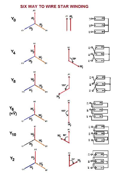
Six Ways to wire Star Winding:
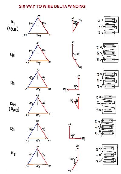
Six Ways to wire Delta Winding:
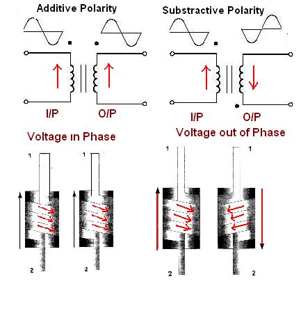
POLARITY:
- An ac voltage applied to a coil will induce a voltage in a second coil where the two are linked by a magnetic path. The phase relationship of the two voltages depends upon which way round the coils are connected. The voltages will either be in-phase or displaced by 180 deg. * When 3 coils are used in a 3 phase transformer winding a number of options exist. The coil voltages can be in phase or displaced as above with the coils connected in star or delta and, in the case of a star winding, have the star point (neutral) brought out to an external terminal or not.
- When Pair of Coil of Transformer have same direction than voltage induced in both coil are in same direction from one end to other end. * When two coil have opposite winding direction than Voltage induced in both coil are in opposite direction.
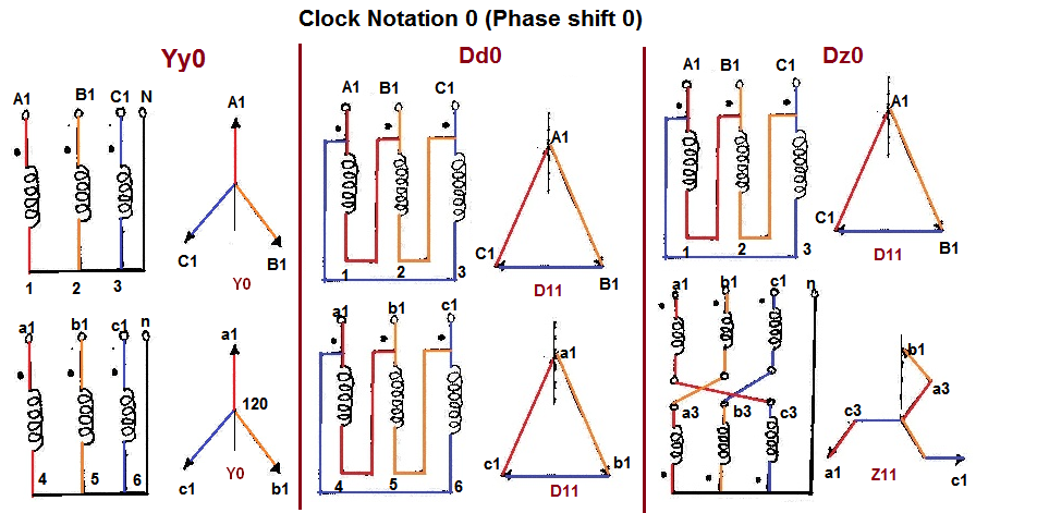
WINDING CONNECTION DESIGNATIONS:
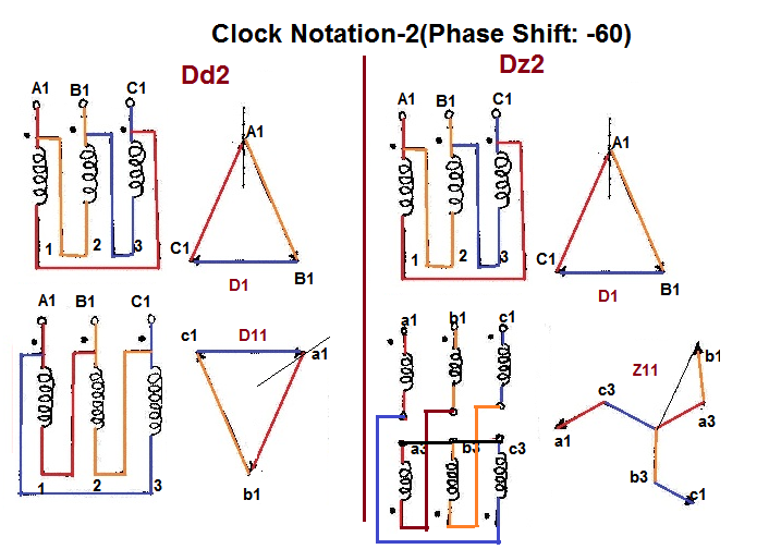
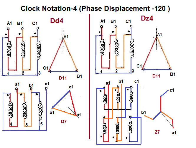
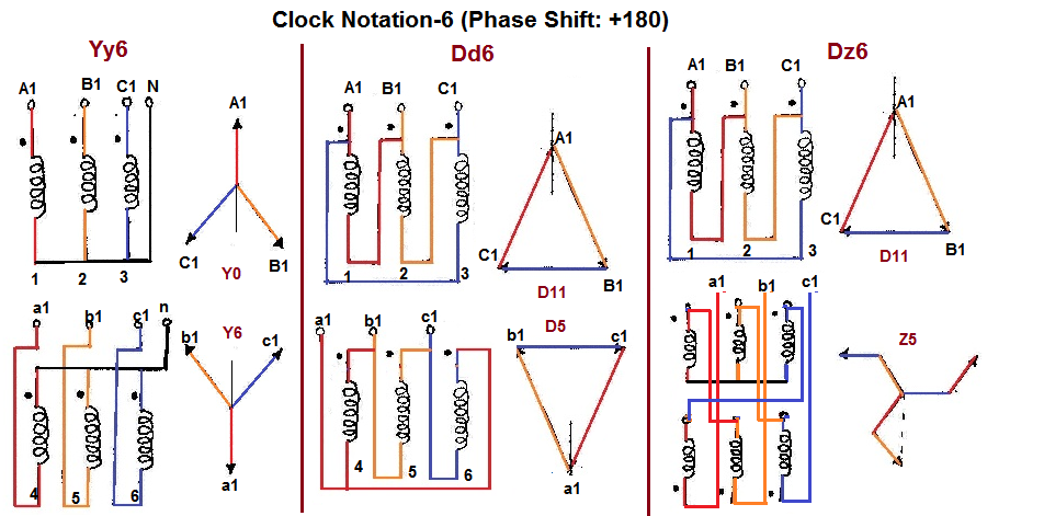
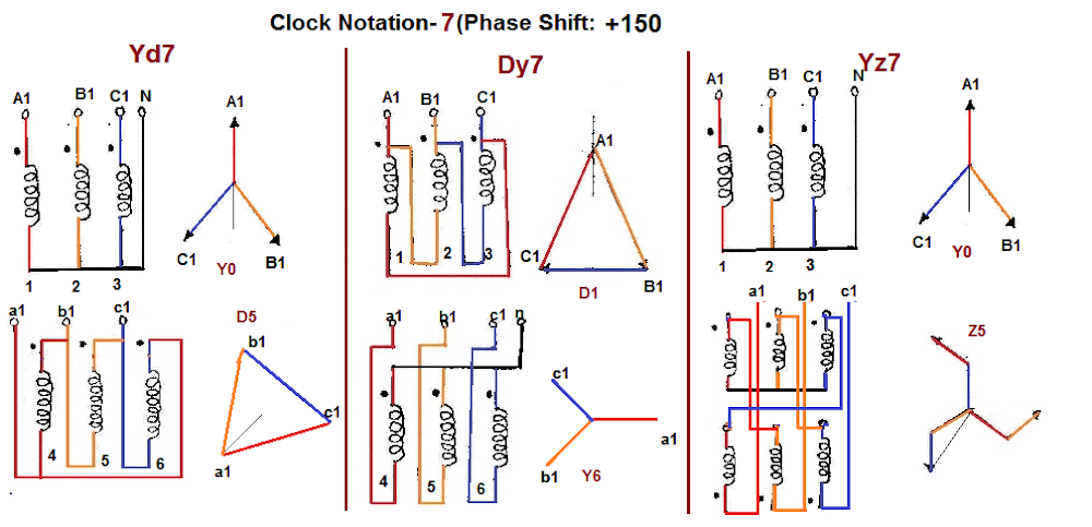
- First Symbol: for High Voltage: Always capital letters. * D=Delta, Y=Star, Z=Interconnected star, N=Neutral * Second Symbol: for Low voltage: Always Small letters. * d=Delta, y=Star, z=Interconnected star, n=Neutral. * Third Symbol: Phase displacement expressed as the clock hour number (1,6,11) * Example – Dyn11 Transformer has a delta connected primary winding (D) a star connected secondary (y) with the star point brought out (n) and a phase shift of 30 deg leading (11). * The point of confusion is occurring in notation in a step-up transformer. As the IEC60076-1 standard has stated, the notation is HV-LV in sequence. For example, a step-up transformer with a delta-connected primary, and star-connected secondary, is not written as ‘dY11’, but ‘Yd11’. The 11 indicates the LV winding leads the HV by 30 degrees. * Transformers built to ANSI standards usually do not have the vector group shown on their nameplate and instead a vector diagram is given to show the relationship between the primary and other windings.
VECTOR GROUP OF TRANSFORMER:
- The three phase transformer windings can be connected several ways. Based on the windings’ connection, the vector group of the transformer is determined. * The transformer vector group is indicated on the Name Plate of transformer by the manufacturer. The vector group indicates the phase difference between the primary and secondary sides, introduced due to that particular configuration of transformer windings connection. * The Determination of vector group of transformers is very important before connecting two or more transformers in parallel. If two transfor…