
EHV/HV Cable Sheath Earthing
EHV/HV CABLE SHEATH EARTHING
EHV/HV CABLE SHEATH EARTHING:
INTRODUCTION:
- In urban areas, high voltage underground cables are commonly used for the transmission and distribution of electricity. Such high voltage cables have metallic sheaths or screens surrounding the conductors, and/or armour and metallic wires surrounding the cables. During earth faults applied to directly earthed systems, these metallic paths are expected to carry a substantial proportion of the total fault current, which would otherwise flow through the general mass of earth, while returning to system neutrals. These alternative return paths must be considered when determining the extent of the grid potential rise at an electrical plant due to earth faults. * For safety and reliable operation, the shields and metallic sheaths of power cables must be grounded. Without grounding, shields would operate at a potential considerably above ground. Thus, they would be hazardous to touch and would cause rapid degradation of the jacket or other material intervening between shield and ground. This is caused by the capacitive charging current of the cable insulation that is on the order of 1 mA/ft of conductor length. * This current normally flows, at power frequency, between the conductor and the earth electrode of the cable, normally the shield. In addition, the shield or metallic sheath provides a fault return path in the event of insulation failure, permitting rapid operation of the protection devices. * In order to reduce Circulating current and electric potential difference between the sheathings of single core three-phase cables, the sheathing is grounded and bonded at one or both ends of the cables. If the cable is long, double bonding has to be carried out which leads to circulating currents and increased total power loss. Raising the sheath’s resistance, by decreasing its cross section and increasing its resistivity, can reduce this almost to the level of the core losses. * However, in case of an earth fault, a considerable portion of the fault current flows through the increased sheath resistance, creating much higher power in the sheaths than in the faulty core. A simple solution, a conductor rod buried into the soil above or under the cable can divert this power from the sheaths.
CABLE SCREEN:
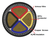
(1) PURPOSE OF CABLE SCREEN:
-
- Cable screen controls the electric field stress in the cable insulation. * Cable Screen Provides return path for Cable neutral and fault current. * If the screen is earthed at two ends than it provides Shielding for electromagnetic radiation. * Enclosing dangerous high voltage with earth potential for safety.
(2) PURPOSE OF BONDING CABLE SCREENS AT BOTH ENDS:
- The electric power losses in a cable circuit are dependent on the currents flowing in the metallic sheaths of the cables so by reducing the current flows in metallic sheath by different methods of bonding we can increases the load current carrying capacity (ampacity) of the cable. * It provides low impedance fault current return path and provides neutral point for the circuit. * It provides shielding of electromagnetic field.
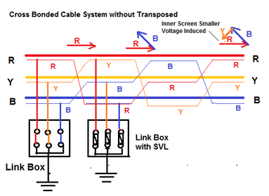
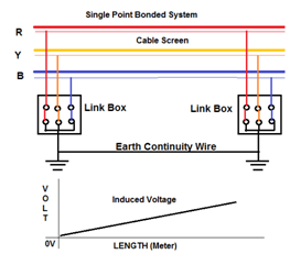
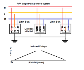
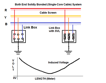
(3) INDUCED VOLTAGE & CIRCULATING CIRCULATING CURRENT IN CABLE SCREEN:
- Electromagnetic coupling between the core and screen Electromagnetic screen. * If the cable screen is single point bonded, no electrical continuity and mmf generates a voltage. * If the cable screen is bonded at both ends, the mmf will cause circulating current to flow if there is electrical continuity. * The circulating current produces an opposing magnetic field. * Suitable bonding method should be employed to meet the standing voltage limit and keep Circulating current to an acceptable level.
LAYING METHOD OF CABLE:
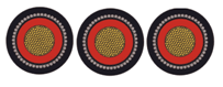
- The three Single core cables in a 3-phase circuit can be placed in different formations. Typical formations include trefoil (triangular) and flat formations.
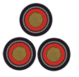
(1) TREFOIL FORMATION:
- To minimize the electromechanical forces between the cables under short-circuit conditions, and to avoid eddy-current heating in nearby steelwork due to magnetic fields set up by load currents, the three single-core cables comprising the three phases of a 3-phase circuit are always run clamped in ‘Trefoil’ formation. * Advantage:
- This type of Formation minimizes the sheath circulating currents induced by the magnetic flux linking the cable conductors and metallic sheath or copper wire screens. 2. This configuration is generally used for cables of lower voltages (33 to 132kV) and of smaller conductor sizes.
- Disadvantages:
- The trefoil formation is not appropriate for heat dissipation because there is an appreciable mutual he…