

Auto Transformer Connection
AUTO TRANSFORMER CONNECTION
(7) AUTO TRANSFORMER CONNECTION:
-
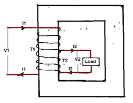
An Ordinary Transformer consists of two windings called primary winding and secondary winding. These two windings are magnetically coupled and electrically isolated. But the transformer in which a part of windings is common to both primary and secondary is called Auto Transformer. * In Auto Transformer two windings are not only magnetically coupled but also electrically coupled. The input to the transformer is constant but the output can be varied by varying the tapings. * The autotransformer is both the most simple and the most fascinating of the connections involving two windings. It is used quite extensively in bulk power transmission systems because of its ability to multiply the effective KVA capacity of a transformer. Autotransformers are also used on radial distribution feeder circuits as voltage regulators. The connection is shown in Figure
-
The primary and secondary windings of a two winding transformer have induced emf in them due to a common mutual flux and hence are in phase. The currents drawn by these two windings are out of phase by 180◦. This prompted the use of a part of the primary as secondary. This is equivalent to common the secondary turns into primary turns. * The common section need to have a cross sectional area of the conductor to carry (I2−I1) ampere. * Total number of turns between A and C are T1. At point B a connection is taken. Section AB has T2 turns. As the volts per turn, which is proportional to the flux in the machine, is the same for the whole winding, V1 : V2 = T1 : T2 * When the secondary winding delivers a load current of I2 Ampere the demagnetizing ampere turns is I2T2. This will be countered by a current I1 flowing from the source through the T1 turns such that, I1T1 = I2T2 * A current of I1 ampere flows through the winding between B and C. The current in the winding between A and B is (I2 − I1) ampere. The cross section of the wire to be selected for AB is proportional to this current assuming a constant current density for the whole winding. Thus some amount of material saving can be achieved compared to a two winding transformer. The magnetic circuit is assumed to be identical and hence there is no saving in the same. To quantify the saving the total quantity of copper used in an auto transformer is expressed as a fraction of that used in a two winding transformer As * copper in auto transformer / copper in two winding transformer =((T1 − T2)I1 + T2(I2 − I1))/T1I1 + T2I2 * copper in auto transformer / copper in two winding transformer = 1 –(2T2I1 / (T1I1 + T2I2)) * But T1I1 = T2I2 so * The Ratio = 1 –(2T2I1 / 2T1I1) = 1 –(T2/T1) * This means that an auto transformer requires the use of lesser quantity of copper given by the ratio of turns. This ratio therefore the savings in copper. * As the space for the second winding need not be there, the window space can be less for an auto transformer, giving some saving in the lamination weight also. The larger the ratio of the voltages, smaller is the savings. As T2 approaches T1 the savings become significant. Thus auto transformers become ideal choice for close ratio transformations.
-
The auto transformer shown in Figure is connected as a boosting auto transformer because the series winding boosts the output voltage. Care must be exercised when discussing ‘‘primary’’ and ‘‘secondary’’ voltages in relationship to windings in an auto transformer.
-
In two-winding transformers, the primary voltage is associated with the primary winding, the secondary voltage is associated with the secondary winding, and the primary voltage is normally considered to be greater than the secondary voltage. In the case of a boosting autotransformer, however, the primary (or high) voltage is associated with the series winding, and the secondary (or low) voltage is associated with the common winding; but the voltage across the common winding is higher than across the series winding.
LIMITATION OF THE AUTOTRANSFORMER
- One of the limitations of the autotransformer connection is that not all types of three-phase connections are possible. For example, the ∆-Y and Y- ∆ connections are not possible using the autotransformer. The Y-Y connection must share a common neutral between the high-voltage and low-voltage windings, so the neutrals of the circuits connected to these windings cannot be isolated. * A ∆- ∆ autotransformer connection is theoretically possible; however, this will create a peculiar phase shift. The phase shift is a function of the ratio of the primary to secondary voltages and it can be calculated from the vector diagram. This phase shift cannot be changed or eliminated and for this reason, autotransformers are very s…