


HV Cable Termination Method and Precaution-PART-2
HV CABLE TERMINATION METHOD AND PRECAUTION. (PART-2)
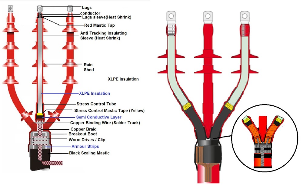
BASIC STRUCTURE OF HIGH VOLTAGE CABLES
- High-voltage cables generally consist of nine layers.
aaa
- The basic structure of high voltage cables is
(1) OUTER SHEATH:
- It protects cable from the moisture and environment. It also provides protection against mechanical impact on cable. * Outer sheath material is mostly Polyethylene
(2) ARMOR LAYER.
- Armor provides mechanical Strength to the cable, certain resistance to external force, and prevents animal bite, external mechanical impact on cable.
(3) INNER SHEATH:
- Inner protective sheath can keep Cable XLPE Insulation layer away from water, air and other objects, avoiding moisture and mechanical injury on internal insulation layer. * It protects the cable core. * Inner Sheath Material is same as outer sheath material, mostly Polyethylene
(4) PACKAGE AND FILLER LAYER.
- It helps to organizes several cable cores into circular shape, for the convenience of packaging and cabling. * It also provides protection to the cable Core.
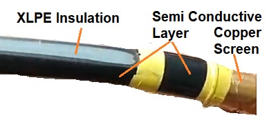
(5) COPPER SHIELDING SCREEN.
- The main function of copper screen is to equalize the electric field and help improve the electric field distribution. * The other function is to ground the short circuit current. * When cable is charged it’s produced strong electrical filed around the core, Copper Shielding equalize this electrical filed and improve uniformity of electrical field distribution surrounding the core which restrict the interference of strong electric field around on core in the cable. * Hence, if copper shielding layer in cable doesn’t exist, then insulation breakdown between core and core will be damaged.
(6) SEMI CONDUCTIVE LAYER (OUTER SEMI CON LAYER).
- There may be small clearance or air gap between in XLPE insulation and copper shielding screen which is one of the main factors causing partial discharge. * Semi Conductive material have good contact properties hence semiconductive layer is provided between XLPE Insulation and copper screen to avoid the partial discharge between insulation layer and protective layer.
(7) XLPE INSULATION LAYER.
- The cable insulation provides electrical insulation to the conductor at voltage from the outer screens at ground potential. * The insulation will be of sufficient thickness to withstand the electric field under the rated and transient operating conditions. * XLPE (cross-linked polyethylene) is good insulating materials. * XLPE has high breakdown strength, high insulation resistance, low dielectric loss, excellent tree discharge- resistance performance and long insulation performance period, etc.
(8) CONDUCTOR SHIELDING LAYER (INNER SEMI CON LAYER).
- Conductor shielding layer can improve the electric field distribution. * This layer reduces the probability of occurrence of partial discharge. * The cable conductor is made stranding of wires hence it surface is not smooth which creates air gap between insulation layer and conductor. This will cause the concentration of electric field. * Conductor is covered by Inner Conductor shielding layer of semiconductor materials on the surface of the conductor for good contact with insulation layer.
HV CABLE TERMINATION PROCEDURE:
GENERAL INSTRUCTIONS
- Use a propane gas torch with a soft yellow flame for shrinking components. * Avoid a pencil type flame which is caused by unregulated supply * Keep the flame on the moving direction to ensure even shrinkage of all the materials and also helps to reduce scorching * Ensure that all components are kept clean and grease free during installation * Allow to cool before applying any mechanical strain * Read the instructions carefully before starting. * Clean and degrease all parts which will be in contact with tapes and adhesives. * Personnel should be proficient and knowledgeable for preparing and installing medium voltage terminations.
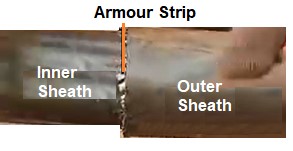
(1) REMOVE OUTER CABLE INSULATION SHEATH:
- Calculate approximate Terminate length of Cable from following Table.
2
Voltage Indoor (L) Outdoor (L) x 7.2KV 650mm 700mm Length 0f Lugs +5mm 12KV 650mm 700mm 17.5KV 650mm 700mm 24KV 700mm 800mm 36KV 800mm 900mm The “L” dimension should not be longer than the distance between bushing centers and base plate.
3
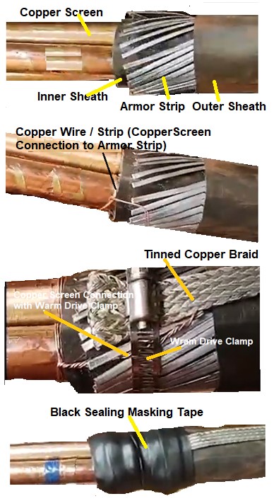
- Strip of and removed Outer Sheath of Cable for Length “L”. * Removed Armored from Length “L”. * Make smooth edge of Sharp armour. * Bend / Fold Armour up to 50mm. * Bind Armour on the outer sheath with use of Copper Wire / Clamp.
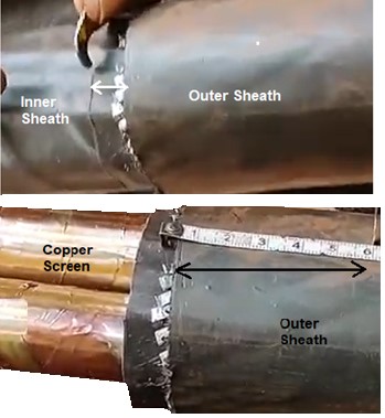
(2) REMOVE INNER CABLE INSULATION SHEATH:
- Removed Inner Cable Sheath 10mm length from Armour with the help of knife. * Removed extra parts of cable which used to make cable round, i.e., Filler, Binding rope / Strip
4
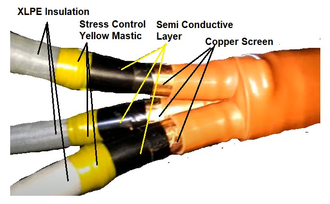
(3) EARTHING ARRANGEMENT OF COPPER SCREEN.
- Marking with the help of tape from100mm length from inner sheath on Cu Screen. * Removed extra Copper Screen from this marking tap t…