


Type of Electrical Power Distribution systems
TYPE OF ELECTRICAL POWER DISTRIBUTION SYSTEMS
TYPE OF ELECTRICAL POWER DISTRIBUTION SYSTEMS:
- Electrical power is distribution either three wires or Four wires (3 wire for phases and 1 wire for Neutral). Voltage between Phase to Phase Called Line Voltage and Voltage between Phase and Neutral is Called Phase Voltage. * This Forth wire may or may not be distributed in Distribution System and Same way this neutral may or may not be earthed * Depending of this neutral condition (Earthed-not Earthed-access-not access) there are various type of earthing System. * The neutral may be directly connected to earth or connected through a resistor or a reactor. This system is called directly earthed or Earthed System. * When a connection has not been made between the neutral point and earth, we say that the neutral is unearthed. * In a network, the earthing system plays a very important role. When an insulation fault occurs or a phase is accidentally earthed, the values taken by the fault currents, the touch voltages and over voltages are closely linked to the type of neutral earthing connection. * A directly earthed neutral strongly limits over voltages but it causes very high fault currents, here as an unearthed neutral limits fault currents to very low values but encourages the occurrence of high over voltages. * In any installation, service continuity in the event of an insulation fault is also directly related to the earthing system. An unearthed neutral permits service continuity during an insulation fault. Contrary to this, a directly earthed neutral, or low impedance-earthed neutral, causes tripping as soon as the first insulation fault occurs. * The choice of earthing system in both low voltage and medium voltage networks depends on the type of installation as well as the type of network. It is also influenced by the type of loads and service continuity required. * The Main objectives of an earthing system are Provide an alternative path for the fault current to flow so that it will not endanger the user, Ensure that all exposed conductive parts do not reach a dangerous potential, Maintain the voltage at any part of an electrical system at a known value and prevent over current or excessive voltage on the appliances or equipment. * Different earthing systems are capable of carrying different amounts of over current. Since the amount of over current produced in different types of installation differs from each other, required type of earthing will also differ according to the type of installation. so in order to ensure that the installation goes with the existing earthing system or else to do any modification accordingly, we need to have a proper idea of the present earthing system. It would enhance the safety as well as the reliability * As per IEC 60364-3 There are three types of systems:
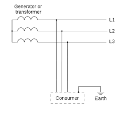
(1) Unearthed System:
- IT System.
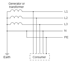
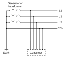
(2) Earthed System:
- TT * TN (TN-S, TN-C, TN-C-S). * The first letter defines the neutral point in relation to earth:
- T = directly earthed neutral (from the French word Terre) 2. I =unearthed or high impedance-earthed neutral (e.g. 2,000 Ω)
- The second letter defines the exposed conductive parts of the electrical installation in relation to earth:
- T =directly earthed exposed conductive parts 2. N =exposed conductive parts directly connected to the neutral conductor
UNEARTHED SYSTEM:
(1) IT SYSTEM UNEARTHED (HIGH IMPEDANCE EARTHED NEUTRAL)
-
First Letter I= the neutral is unearthed at Transformer or Generator side. * Second Letter T= Frame parts of the loads are interconnected and earthed at Load Side
-
is compulsory to install an over voltage limiter between the MV/LV transformer neutral point and earth.
-
If the neutral is not accessible, the overvoltage limiter is installed between a phase and earth. * It runs off external over voltages, transmitted by the transformer, to the earth and protects the low voltage network from a voltage increase due to flashover between the transformer’s medium voltage and low voltage windings.
Advantages:
- System providing the best service continuity during use. 2. When an insulation fault occurs, the short-circuit current is very low. 3. Higher operational safety only a capacitive current flows, which is caused by the system leakage capacitance if an earth fault occurs. 4. Better accident prevention the fault current is limited by the body impedance, earthing resistance and the high impedance of the earth fault loop.
Disadvantages:
- Requires presence of maintenance personnel to monitor and locate the first fault during use. 2. Requires a good level of network insulation (High leakage current must be supplied by insulating transformers). 3. Overvoltage limiters must be installed. 4. Requires all the installation’s exposed conductive parts to be …