
Ferranti Effect in Transmission Line
FERRANTI EFFECT
WHAT IS FERRANTI EFFECT
- A long transmission line draws a substantial quantity of charging current. If such a line is open circuited or very lightly loaded at the receiving end, Receiving end voltage being greater than sending end voltage in a transmission line is known as Ferranti effect. All electrical loads are inductive in nature and hence they consume lot of reactive power from the transmission lines. Hence there is voltage drop in the lines. Capacitors which supply reactive power are connected parallel to the transmission lines at the receiving end so as to compensate the reactive power consumed by the inductive loads. * As the inductive load increases more of the capacitors are connected parallel via electronic switching. Thus reactive power consumed by inductive loads is supplied by the capacitors thereby reducing the consumption of reactive power from transmission line. However when the inductive loads are switched off the capacitors may still be in ON condition. The reactive power supplied by the capacitors adds on to the transmission lines due to the absence of inductance. As a result voltage at the receiving end or consumer end increases and is more than the voltage at the supply end. This is known as Ferranti effect.
WHY DOES VOLTAGE RISE ON A LONG, UNLOADED TRANSMISSION LINE?
- The Ferranti Effect occurs when current drawn by the distributed capacitance of the transmission line itself is greater than the current associated with the load at the receiving end of the line. Therefore, the Ferranti effect tends to be a bigger problem on lightly loaded lines, and especially on underground cable circuits where the shunt capacitance is greater than with a corresponding overhead line. This effect is due to the voltage drop across the line inductance (due to charging current) being in phase with the sending end voltages. As this voltage drop affects the sending end voltage, the receiving end voltage becomes greater. The Ferranti Effect will be more pronounced the longer the line and the higher the voltage applied. * The Ferranti Effect is not a problem with lines that are loaded because line capacitive effect is constant independent of load, while inductance will vary with load. As inductive load is added, the VAR generated by the line capacitance is consumed by the load.
HOW TO REDUCE FERRANTI EFFECT:
SHUNT REACTORS AND SERIES CAPACITORS:
-
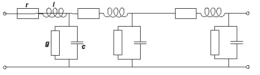
The need for large shunt reactors appeared when long power transmission lines for system voltage 220 kV & higher were built. The characteristic parameters of a line are the series inductance (due to the magnetic field around the conductors) & the shunt capacitance (due to the electrostatic field to earth).
-
Both the inductance & the capacitance are distributed along the length of the line. So are the series resistance and the admittance to earth. When the line is loaded, there is a voltage drop along the line due to the series inductance and the series resistance. When the line is energized but not loaded or only loaded with a small current, there is a voltage rise along the line (the Ferranti-effect) * In this situation, the capacitance to earth draws a current through the line, which may be capacitive. When a capacitive current flows through the line inductance there will be a voltage rise along the line. * To stabilize the line voltage the line inductance can be compensated by means of series capacitors and the line capacitance to earth by shunt reactors. Series capacitors are placed at different places along the line while shunt reactors are often installed in the stations at the ends of line. In this way, the voltage difference between the ends of the line is reduced both in amplitude and in phase angle. * Shunt reactors may also be connected to the power system at junctures where several lines meet or to tertiary windings of transformers. * Transmission cables have much higher capacitance to earth than overhead lines. Long submarine cables for system voltages of 100 KV and more need shunt reactors. The same goes for large urban networks to prevent excessive voltage rise when a high load suddenly falls out due to a failure. * Shunt reactors contain the same components as power transformers, like windings, core, tank, bushings and insulating oil and are suitable for manufacturing in transformer factories. The main difference is the reactor core limbs, which have non-magnetic gaps inserted between packets of core steel. * 3-phase reactors can also be made. These may have 3- or -5-limbed cores. In a 3-limbed core there is strong magnetic coupling between the three phases, while in a 5-limbed core the phases are magnetically independent due to the enclosing magnetic frame formed by the two yokes and the two unwound side-limbs. * The neutral of shunt reactor may be …