


Basic of External Lightning Protection System (LPS)-(Part-3)
BASIC OF EXTERNAL LIGHTNING PROTECTION SYSTEM (LPS)-(PART-3)
September 4, 2024 1 Comment
COMPARISION OF VARIOUS PROTECTION METHOD
COMPARISION OF VARIOUS PROTECTION METHOD
Protection Method Type of Structure Simple structure Complex shaped structure Plane Structure Protection Angle () YES NO NO Mesh Method NO YES YES Rolling sphere Method YES YES YES () This method is not suitable for structure height more than radius of the rolling sphere relevant to the selected protection level of LPS
(2) DOWN CONDUCTOR SYSTEM:
-
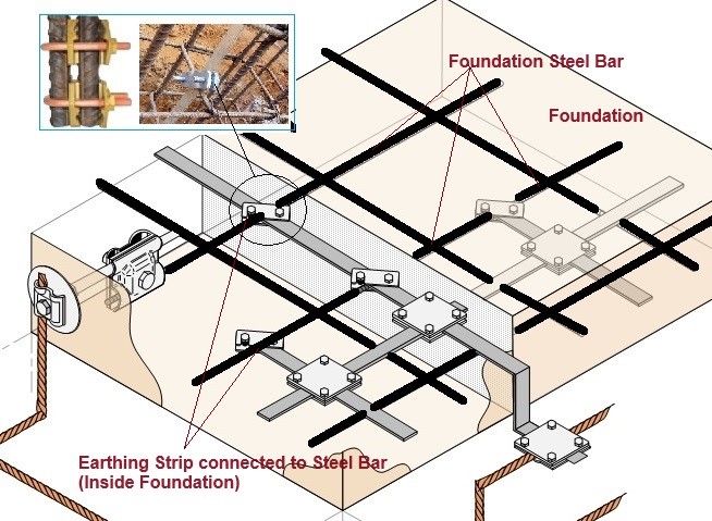
In Air-termination systems, down-conductor systems and earth-termination systems should be harmonized to produce the shortest possible path for the lightning current. * Down-conductors should preferably be connected to junctions of the air-termination system network and routed vertically to the junctions of the earth-termination system network. * The function of a down conductor system is to conduct the lightning impulse from air-termination system to the earthing system. The down conductor system should be installed in such a way that the following points are ensured. * (i) Several parallel current paths exist * (ii) Length of current path is kept to minimum. * (iii) Equipotential bonding to conducting parts is performed. * Selection and installation of down conductors plays a major role in protecting electrical and electronic installations in a building. The number of down conductors to a typical building depends upon the class of LPS. * A down conductor should be installed at each exposed corner of the structure and form a direct continuation of the air-termination conductors. Drown conductors are installed in such a way that they provide the shortest and most direct route to earth. Avoiding the formation of bends and loops is required. * To reduce damage caused by lightning current, the down conductors are arranged so that the current path around the building’s perimeter is parallel and at equal distances. * Even if the down conductor encased in insulating material, down conductors must not be installed in service shafts, gutters, or downspouts, as doing so invites severe damage during a lightning strike. * Electrical insulation between LPS components and other metallic installation in the building are necessary to avoid flashover between different metal parts. * Integration of down conductor with Building Natural Components: * External down-conductors should be installed between the air-termination system and the earth-termination system. Wherever natural components (Steel reinforcement, metal framework structure) are available, they can be used as down-conductors. * Down conductors are also integrated into structural steel reinforcement, metal framework of structure, steel roof, metal façade, handrails etc. is the best and practical solution for new and upcoming high raise buildings. In this integrated approach high safety is offered with no maintenance, long life, no influence on aesthetics. Separation distance need not be considered in this case. * Down conductors can be embedded in RCC columns. In this case, bonding different metallic installations in the building is simple, thereby eliminating potential differences. This integrated method is not only cost-effective but has no negative effect on the building’s aesthetics. It also reduces the failure of electronic equipment inside the building from radiated lightning effects. * Test joints are not required, and earth resistance measurements are not necessary in the location where the natural down conductors are terminated to foundation earthing.
-
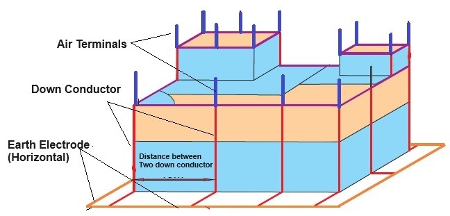
Number & distance between each Down Conductor: * For each non-isolated LPS, the number of down conductors shall be not less than two and should be distributed around the perimeter of the structure to be protected. An equal spacing of the down conductors is preferred around the perimeter. The typical values of the distance between the conductors are shown below.
DISTANCE BETWEEN DOWN CONDUCTORS
(IEC/BS EN 62305-3 Table 4)
Class of LPS Distance between conductors CLASS I- (Very High Risk) 10 Meter CLASS II- (High Risk) 10 Meter CLASS III- (Moderate Risk) 15 Meter CLASS IV- (Low Risk) 20 Meter
- If the distance between down-conductors is too large with the reference to the Table, the number of down-conductors should be increased to meet the required separation distance. * As stated, a down-conductor should be installed at each exposed corner of the structure, where this is possible. However, an exposed each corner does not need a down conductor if the distance between this exposed corner to the nearest down-conductors complies with the following conditions: * (i)the distance to both adjacent down-conductors is half the distance according to Tables or smaller. * (ii) the d…