

Selection of Various Types of Inverter-(Part-1)
SELECTION OF VARIOUS TYPES OF INVERTER-(PART-1)
INTRODUCTION:
- In this modern society, electricity has vital role on the most daily activities for domestic and industrial utilization of electric power for operations. * An inverter is used to provide uninterrupted 220V AC supply to the load connected to its output socket. It provides constant AC supply at its output socket, even when the AC mains supply is not available. * There are many factors, which are affecting on selecting of the best inverter for our application
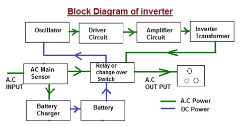
BLOCK DIAGRAM OF INVERTER:
- Power inverter is a device that converts electrical power from DC form to AC form using electronic circuits. It is typical application is to convert battery voltage into conventional household AC voltage to use Equipments, when an AC power is not available. * There are two methods, in which the low voltage DC power is inserted into AC Power. * In First Method first is the conversion of the low voltage DC power to a high voltage DC source, an then It is the conversion of the high DC source to an AC waveform using pulse width modulation. * In Second method the outcome would be to first convert the low voltage DC power to AC, and then use a transformer to boost the voltage to 220 volts. * The widely used method in the current residential inverter is the second. * An Inverter not only converts the DC Voltage of battery to 220V V AC Signals but also charge the Battery when the AC mains are present. * The block diagram shown above is a simple depiction of the way an Inverter Works.
When the AC mains power supply is available.
- When the Utility Company AC mains supply is available. * C Main Sensor: the AC sensor senses it and the 230V A.C supply feeds to the Relay and battery charger. * Relay or Change over Switch: AC main sensor activates a relay and this relay will directly pass the 230V AC mains supply to the Load. * Battery Charger: Battery Charger converts line A.C Voltage to DC Voltage and Charges the Battery even when A.C Power is available. * Battery: Battery is charged and it is stopped when it is full charged.
When the AC mains power supply is not available.
- When the AC mains power supply is not available. * Relay or Change over Switch: AC main sensor activates a relay and this relay will connected to battery in absent of the AC mains supply. * Battery: Battery is providing DC Power to Oscillator circuit through Relay. * Oscillator Circuit: An oscillator circuit inside the inverter use pulse width modulator to generate the 50Hz frequency required to generate AC supply by the inverter. * The battery DC supply is connected to the Oscillator. The flip-flop converts the incoming signal into signals with changing polarity such that in a two-signal with changing polarity. * The first is positive while the second is negative and vice versa. This process is repeated 50times per second to give an alternating signal with 50Hz frequency. This alternating signal is known as “MOS Drive Signal “. * Driver Circuit: The MOS drive signals are given to the base of driver transistor which separated into two different channels. * Amplifier Circuit: The transistors amplify the 50Hz MOS drive signal at their base to a sufficient level and output them from the emitter. * Inverter Transformer: The transformer used for this is a center-tapping which divides the primary into two equal sections. * This center-tapping is connected to the positive terminal of the battery. Two ends of the primary are connected to the negative terminal of the battery through switches S1 and S2. * MOSFETs or Transistors are used for the switching operation. These MOSFETs or Transistors are connected to the primary winding of the inverter transformer. * When these switching devices receive the MOS drive signal from the driver circuit, they start switching between ON & OFF states at a rate of 50 Hz. This switching action of the MOSFETs or Transistors creates a 50Hz current to the primary of the inverter transformer. This results in a 220V AC or 2300V AC (depending on the winding ratio of the inverter transformer) at the secondary or the inverter transformer. This secondary voltage is made available at the output socket of the inverter by a changeover relay.
TYPE OF INVERTER
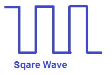
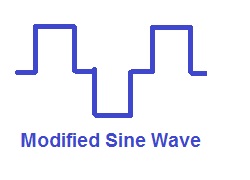
- The inverters are classified by depending on their output * Sine wave * Modified sine wave * Square wave.
(1) SINE WAVE INVERTER:
-
In utility Company Sine wave generated by rotating AC machinery and sine waves is a natural product of rotating AC machinery. * Pure sine wave inverters provide an output same as a sine wave which is similar to the utility supplied grid power, hence Pure Sine Wave inverter produces a better and cleaner current
-
All commercial instruments are designed to run on pure sine…