
Various Routine Test of Power Transformer-(Part-4)
VARIOUS ROUTINE TEST OF POWER TRANSFORMER-(PART-4)
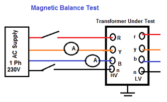
(9) MAGNETIC BALANCE TEST
Test Purpose:
- Magnetic balance test of transformer is conducted only on three phase transformers to check the imbalance in the magnetic circuit.
Test Instrument:
- Multi meter. * Mill Ammeter
Test Circuit Diagram:
Untitled
Test Procedure:
- First keep the tap changer of transformer in normal position. * Now disconnect the transformer neutral from ground. * Then apply single phase 230V AC supply across one of the HV winding terminals and neutral terminal. * Measure the voltage in two other HV terminals in respect of neutral terminal. * Repeat the test for each of the three phases. * In case of auto transformer, magnetic balance test of transformer should be repeated for IV winding also. * There are three limbs side by side in a core of transformer. One phase winding is wound in one limb. The voltage induced in different phases depends upon the respective position of the limb in the core. * The voltage induced in different phases of transformer in respect to neutral terminals given in the table below. * 415V, Two phase supply is to be applied to any two phases terminals on HV side of Power transformer and voltages in other two phase combination are to be measured with LT open. * Sum of the Resultant two values shall be equal to the voltage applied.
Applied Voltage (415V) Measured Voltage(V1) Measured Voltage(V2) Result RY YB BR V=V1+V2 YB RY BR V=V1+V2 BR YB RY V=V1+V2
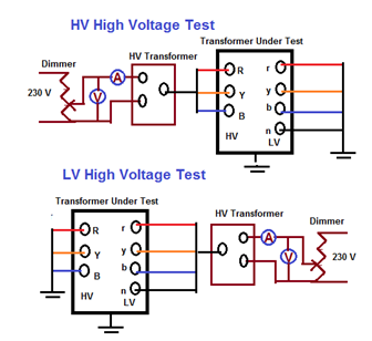
(10) HIGH VOLTAGE TESTS ON HV & LV WINDING:
Test Purpose:
- To checks the insulation property between Primary to earth, Secondary to earth and between Primary & Secondary.
Test Instrument:
- High Voltage tester ( 100KV & 3KV)
Test Circuit Diagram:
Untitled Procedure:
- HV high voltage test: LV winding connected together and earthed. HV winding connected together and given Following HV Supply for 1 minute. * LV high Voltage test: HV winding connected together and earthed. LV winding connected together and given Following HV Supply for 1 minute. * 433V Winding =3KV High Voltage * 11KV Winding =28KV High Voltage * 22KV Winding =50KV High Voltage * 33KV Winding =70KV High Voltage.
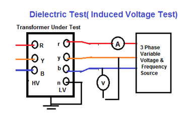
(11) DI ELECTRICAL TEST:
Test Purpose:
- To check the ability of main insulation to earth and between winding * To checks the insulation property between Primary to earth, Secondary to earth and between Primary & Secondary.
Test Instruments:
- 3 Phase Variable Voltage & Frequency Source. * Auto Transformer.
Test Procedure:
- The following Dielectric tests are performed in order to meet the transformer insulation strength expectations. * Switching impulse test: to confirm the insulation of the transformer terminals and windings to the earthed parts and other windings, and to confirm the insulation strength in the windings and through the windings. * Lightning impulse test : to confirm the transformer insulation strength in case of a lightning hitting the connection terminals * Separate source AC withstand voltage test: to confirm the insulation strength of the transformer line and neutral connection terminals and the connected windings to the earthed parts and other windings. * Induced AC voltage test (short duration ACSD and long duration ACLD ) : to confirm the insulation strength of the transformer connection terminals and the connected windings to the earthed parts and other windings, both between the phases and through the winding. * Partial discharge measurement: to confirm the “partial discharge below a determined level” property of the transformer insulation structure under operating conditions.
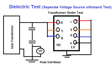
Method No 1 (separate source voltage withstand test) Untitled
- All the terminals of the winding under test should be connected together and the voltage should be applied. * The secondary windings of bushing type current transformers should be connected together and earthed. The current should be stable during test and no surges should occur. * A single phase power frequency voltage of shape approximately sinusoidal is applied for 60 seconds to the terminals of the winding under test. * The test shall be performed on all the windings one by one. * The test is successful if no breakdown in the dielectric of the insulation occurs during test. * During the Separate source AC withstand voltage test, the frequency of the test voltage should be equal to the transformer’s rated frequency or should be not less than 80% of this frequency. In this way, 60 Hz transformers can also be tested at 50 Hz. The shape of the voltage should be single phase and sinusoidal as far as possible. * This test is applied to the star point …