
Various Routine Test of Power Transformer-(Part-3)
VARIOUS ROUTINE TEST OF POWER TRANSFORMER-(PART-3)
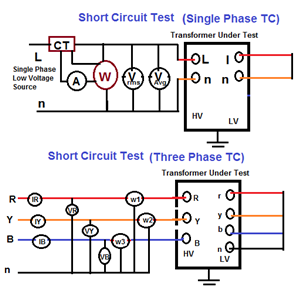
(5) SHORT CIRCUIT TEST
Test Purpose:
- The value of the short circuit impedance Z% and the load (copper) losses (I2R) are obtained. * This test should be performed before the impulse test-if the later will be performed as a routine test- in order to avoid readings errors
Test Instrument:
- Megger or * Multi meter. * CT ,PT
Test Procedure:
- Suitable Low Voltage (3-phase 415V, 50Hz )will be applied to the terminals of one winding (usually the H.V.) with the other winding short circuited with 50 sq. mm. Copper cable. (Usually the L.V.) * The applied voltage is adjusted to pass the needed current in the primary/secondary. In order to simulate conditions nearest to full load, it is customary to pass 100%, 50% or at least 25% of full load current. * Voltage to be increased gradually till the current in the energized winding reaches the required value (50% to 100% rated current). * Measure the 3 Phase line currents at all tap position. If the tap-switch is an Off-Circuit tap-switch, the supply has to be disconnected before changing the tap. A consistent trend in the increase or decrease of current, as the case may be, confirms the healthiness of the transformer. * If transformer is equipped with a tap changer, tapping regulations are applied. * (1) If tapping range within±5% and rated power less than 2500kAV, load loss guarantee refer to the principal tap only. * (2) If tapping range exceeds±5% or rated power above 2500kAV, it shall be stated for which tapping beside the principal tap the load losses will be guaranteed by the manufacturer. * Three phase LT supply is applied on HV side of power transformer at normal tap with rated current on HV side and currents measured in all the phases on HV side and phases & neutral on LV side values noted. * Readings to be taken as quickly as possible as the windings warm up and the winding resistance increases. Hence, the losses value will increase accordingly. * Using appropriate instruments (conventional three watt meter method or digital watt meter with ammeters & voltmeters) measurements of voltage, currents and power can be recorded.
Untitled
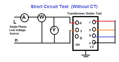
- Short Circuit Test (Without using CT,PT) * To avoid CT’s and PT’s, this method can be used at current levels of 2 to 5 A and measurement of load losses is done at this condition. This measured load loss is then extrapolated to actual load currents to obtain load losses at the operating current. * Example: – 11 kV/433 V, 1000 kVA transformer with 5% impedance, the voltage to be applied on H.V. side during load test is estimated below. * V. side full load current (I1) = (KVAx1000/1.732xLine Voltage) * V. side full load current (I1) =(1000×1000/1.732×11000)=52.5 Amp * Line to line voltage to be applied on H.V side for getting 5 A on H.V. side, * Line to line voltage to be applied on H.V side Visc= (Line Voltagex1000xZx5/0.866xI1x100) * Line to line voltage to be applied on H.V side Visc=(11x1000x5xx/x0.866×52.5×100)=60.5 volts. * Since the current drawn on H.V. side is only about 5A in this test, CT’s can be avoided and hence phase angle error is not applicable.
Untitled
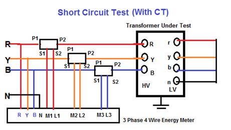
- Short Circuit Test (With using CT,PT)
Untitled Criteria:
- Measured impedance to be within guaranteed value and nameplate value. * Load losses to be within guaranteed values.
Test can detect:
- Winding deformation. * Deviation in name plate value.
(6) OPEN CIRCUIT / NO LOAD TEST
Test Purpose:
- In this test, the value of No-Load power (Po) & the No-Load current (Io) are measured at rated voltage & frequency.
Test Instruments:
- Watt meters. * Ammeter , Voltmeter or * Power analyses
Test Procedure:
- Test is performed at rated frequency. * Three phase LT Voltage of 415 V applied on HV side of Power transformer keeping LT open * Two voltmeters are connected to the energized winding, one is measuring the voltage mean value and the other is for the Voltage R.M.S value. * Voltage applied to winding (usually to H.V. windings).It will be in a range from 90% of winding rated voltage to 110% of the same in steps, each of 5% (i.e. for a 33/11kV transformer, applied voltage values will be 29.7kV, 31.35kV,36.3kV) * Readings of watt meters, Voltmeters & Ammeters are recorded to obtain the values of V (r.m.s), Vmean, Po and Io at each voltage step. * Test results are considered satisfactory if the readings of the two are equal within 3%. If it’s more than 3%, the validity of the test is subjected to agreement. * Measured value of power loss is corrected according to the following formula: * Pc=Pm (1+d) * D= (Vmean – Vr.m.s) / Vmean * Measure the…