


Method for Installation of HVAC System (Part-3)
METHOD FOR INSTALLATION OF HVAC SYSTEM (PART-3)
(C) Y JOINTS
-
Confirm the Y branching piping matches allowable designs from the Installation Manual
-
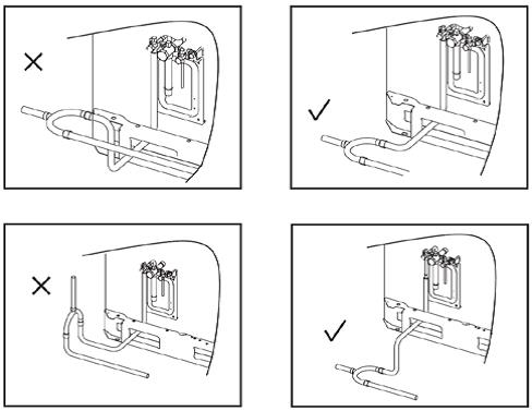
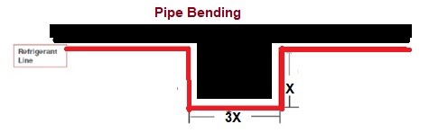
Installed with single end of Y Joints always towards outdoor unit. * The branch joint of outdoor side must be installed horizontally. * The branch joint of indoor side can be installed horizontally or vertically. * Y Joints are supported before and after. * “Y” joints are the correct size and match the locations as shown on the Selection Report. * Maintain a minimum distance of 20″ between branching joints, headers, elbows and equipment. * Recommend horizontal runs to be 3 times that of the vertical when traps cannot be avoided
-
Between two branch joints ≥1m * Between branch joints and indoor unit ≥0.5m * From the inlet or outlet of branch joint, there should be straight pipe with length at least 0.5m
(D) COPPER PIPE LENGTH:
The permitted length and drop difference
Pipe length Max. pipe length <= 240 Meter Equivalent length from the first branch to the farthest indoor unit <= 40 Meter Drop height Drop height between indoor unit and outdoor unit <= 110 Meter Drop height between indoor units <= 30 Meter
- Record the actual liquid pipe length for future reference when charging additional refrigerant.
Split AC Copper Pipe Length
A.C Capacity Maximum Pipe Length Maximum Indoor & Outdoor Height Difference 0.5 Ton 15 Meter 5 Meter 0.6 Ton 15 Meter 5 Meter 0.75 Ton 15 Meter 5 Meter 1 Ton 20 Meter 10 Meter 1.5 Ton 25 Meter 10 Meter 2 Ton 25 Meter 10 Meter 2.5 Ton 30 Meter 10 Meter 3 Ton 30 Meter 20 Meter 3.5 Ton 30 Meter 20 Meter 4 Ton 30 Meter 20 Meter
(E) DRAIN PIPE
- Water leakage test * Check leakage of water pipe After finished installation of drainage pipe, filled the pipe with water, * Waiting for 24 hours to check whether there’s any leakage. * Check leakage from the indoor unit * Charge water from the check hole of indoor unit to check whether the water can be exhausted smoothly or not
Size of Drain Pipe
Condensate water volume : V (L/h)=Indoor Unit (HP)x2 I.D (mm) Thickness (mm) V ≤ 14 Φ 25 3 14 < V ≤ 88 Φ 30 3.5 88 < V ≤ 175 Φ 40 4 175 < V ≤ 334 Φ 50 4.5 334 < V Φ 80 6 *If Slop is <1% than select next higher Size of Drain Pipe
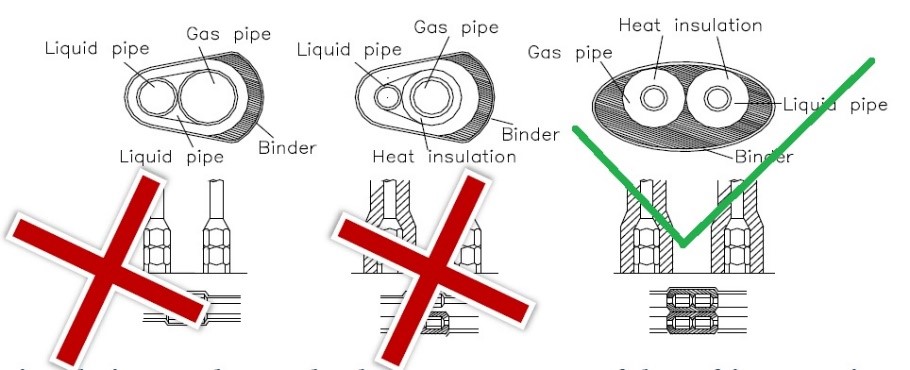
(F) INSULATION OF REFRIGERANT PIPE & DRAIN PIPE
-
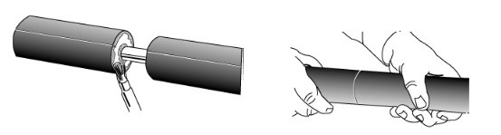
The slip-on method of installation is used for insulation on new refrigeration piping * The inside of the insulation is coated with a powdered lubricant, making it easy to slip the insulation over the pipe. * Small amounts of powdered lubricant may enter the open ends of pipe or tubing. This dust must be kept out of refrigeration systems. Plug the open ends of pipe before slipping on the insulation. * Apply insulation only when the pipes are clean, dry, and unheated or uncooled. The surface to be insulated must be free of rust. * Never stretch insulation when sealing the joints. It is better to compress it slightly. Use pieces of insulation that are at least as long as the section of pipe to be insulated. * Always use the insulation that is properly sized for the pipe it is to cover. Do not stretch it over the pipe. * Do not crowd insulation-covered pipes. Space pipes far enough apart to allow for the free circulation of air. Air movement is an extra safeguard against surface condensation of cold pipes, especially under hot, humid conditions.
-
All piping insulation must be properly sealed to minimize heat loss and control condensation. On cold lines, open pipe insulation joints may allow the formation of condensation, increasing the potential for or contributing to possible pipe or tubing corrosion. Seal insulation joints * Do not compress piping insulation at joists, studs, columns, ducts, hangers, etc. This is important because the insulation will lose thermal efficiency where it is compressed. On cold systems, surface condensation may occur where insulation is compressed * Apply a coating of an approved contact-type adhesive to both butt ends to be joined.
-
Before butting the ends together, allow the adhesive to set until it is dry to the touch but still tacky under slight pressure. Join the surfaces. * Cut open the inside wall of the elbow, taking care not to damage the opposite wall. The slit-open elbow should slip over the fitting. Apply adhesive to the seam (not to the butt ends), allow to tack dry, and fit over the fitting. Press the seams together working from the ends toward the center of the elbow.