
1. Calculate Numbers of Plate/Pipe/Strip Earthing’s (Part-3)
CALCULATE NUMBERS OF PLATE/PIPE/STRIP EARTHINGS (PART-3)
CALCULATE MIN. CROSS SECTION AREA OF EARTHING CONDUCTOR:
-
Cross Section Area of Earthing Conductor As per IS 3043
-
CROSS SECTION AREA OF EARTHING CONDUCTOR (A) =(IF X√T) / K
-
Where t= Fault current Time (Second). * K= Material Constant. * Example: * Calculate Cross Section Area of GI Earthing Conductor for System has 50KA Fault Current for 1 second. Corrosion will be 1.0 % Per Year and No of Year for Replacement is 20 Years. * Cross Section Area of Earthing Conductor (A) =(If x√t) / K * Here If=50000 Amp * T= 1Second * K=80 (Material Constant, For GI=80, copper K=205, Aluminium K=126). * Cross Section Area of Earthing Conductor (A) =(50000×1)/80 * Cross Section Area of GI Earthing Conductor (A)=625 Sq.mm * Allowance for Corrosion = 1.0 % Per Year & Number of Year before replacement say = 20 Years * Total allowance = 20 x 1.0% = 20% * Safety factor = 1.5 * Required Earthing Conductor size = Cross sectional area x Total allowance x Safety factor * Required Earthing Conductor size = 1125 Sq.mm say 1200 Sq.mm * Hence, Considered 1Nox12x100 mm GI Strip or 2Nox6 x 100 mm GI Strips
THUMB RULE FOR CALCULATE NUMBER OF EARTHING ROD:
-
The approximate earth resistance of the Rod/Pipe electrodes can be calculated by
-
EARTH RESISTANCE OF THE ROD/PIPE ELECTRODES R= K X Ρ/L
-
Where ρ = Resistivity of earth in Ohm-Meter * L= Length of the electrode in Meter. * d= Diameter of the electrode in Meter. * K=0.75 if 25< L/d < 100. * K=1 if 100 < L/d < 600 * K=1.2 o/L if 600 < L/d < 300
-
NUMBER OF ELECTRODE IF FIND OUT BY EQUATION OF R(D) =(1.5/N) X R
-
Where R(d) = Desired earth resistance * R= Resistance of single electrode * N= No. of electrodes installed in parallel at a distance of 3 to 4 Meter interval. * Example: * Calculate Earthing Pipe Resistance and Number of Electrode for getting Earthing Resistance of 1 Ω ,Soil Resistivity of ρ=40, Length=2.5 Meter, Diameter of Pipe= 38 mm. * Here L/d = 2.5/0.038=65.78 so K=0.75 * The Earth Resistance of the Pipe electrodes R= K x ρ/L =0.75×65.78=12 Ω * One electrode the earth resistance is 12 Ω. * To get Earth resistance of 1 Ω the total Number of electrodes required =(1.5×12)/1 =18 No
CALCULATING RESISTANCE & NUMBER OF EARTHING ROD:
-
Reference: As per EHV Transmission Line Reference Book page: 290 and Electrical Transmission & Distribution Reference Book Westinghouse Electric Corporation, Section-I Page: 570-590.
-
EARTHING RESISTANCE OF SINGLE RODS: R = ΡX[LN (2L/A)-1]/(2×3.14XL)
-
EARTHING RESISTANCE OF PARALLEL RODS: R = ΡX[LN (2L/A]/ (2×3.14XL)
-
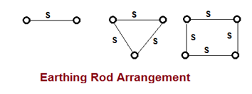
Where L= length of rod in ground Meter, * a= radius of rod Meter * ρ = ground resistivity, ohm- Meter * A= √(axS) * S= Rod separation Meter
Untitled
FACTOR AFFECTS ON GROUND RESISTANCE:
- The NEC code requires a minimum ground electrode length of 2.5 meters (8.0 feet) to be in contact with the soil. But, there are some factor that affect the ground resistance of a ground system: * Length / Depth of the ground electrode: double the length, reduce ground resistance by up to 40%. * Diameter of the ground electrode: double the diameter, lower ground resistance by only 10%. * Number of ground electrodes: for increased effectiveness, space additional electrodes at least equal to the depth of the ground electrodes. * Ground system design: single ground rod to ground plate.
THE GI EARTHING CONDUCTOR SIZES FOR VARIOUS EQUIPMENTS:
No Equipments Earth Strip Size
1
HT switchgear, structures, cable trays & fence, rails, gate and steel column
55 X 6 mm (GI)
2
Lighting Arrestor
25 X 3 mm (Copper)
3
PLC Panel
25 X 3 mm (Copper)
4
DG & Transformer Neutral
50X6 mm (Copper)
5
Transformer Body
50X6 mm (GI)
6
Control & Relay Panel
25 X 6 mm (GI)
7
Lighting Panel & Local Panel
25 X 6 mm (GI)
8
Distribution Board
25 X 6 mm (GI)
9
Motor up to 5.5 kw
4 mm2 (GI)
10
Motor 5.5 kw to 55 kw
25 X 6 mm (GI)
11
Motor 22 kw to 55 kw
40 X 6 mm (GI)
12
Motor Above 55 kw
55 X 6 mm (GI)
Selection of Earthing System:
Installations/ Isc Capacity
IR Value Required
Soil Type/ Resistivity
Earth System
House hold earthing/3kA 8 ohm Normal Soil/ up to 50 ohm-meter Single Electrode Sandy Soil/ between 50 to 2000 ohm- meter Single Electrode Rocky Soil/ More than 2000 ohm- meter Multiple Electrodes Commercial premises,Office / 5kA 2 ohm Normal Soil/ up to 50 ohm-meter Single Electrode Sandy Soil/ between 50 to 2000 ohm- meter Multiple Electrodes Rocky Soil/ More than 2000 ohm- meter Multiple Electrodes Transformers, substationearthing, LT line equipment/ 15kA less than 1 ohm Normal Soil/ up to 50 ohm-meter Single Electrode Sandy Soil/ between 50 to 2000 ohm- meter Multiple Electrodes Rocky Soil/ More than 2000 ohm- meter Multiple Electrodes LA, High current Equipmen…