
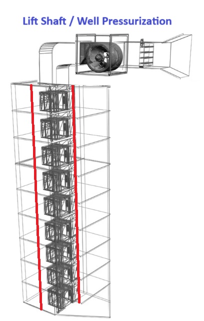
10. Calculate Size of Lift Pressurization Fan for Highrise Building
CALCULATE SIZE OF LIFT PRESSURIZATION FAN FOR HIGHRISE BUILDING
June 22, 2025 1 Comment
Calculate Size Lift Well Pressurization Fan having following Details
- Type of Building is Commercial and Sprinkler Protected * Number of Lift Door (Basement to Terrace) is 17 Nos (B+G+15) * Lift Shaft width is 3600mm and Length is 3600mm * Lift Shaft height is 45 Meter * Vent window Size at Top of Lift Shaft is 320mm to 320mm * Lift Door width is 1 meter and Height is 1.2 meter. * No of Lift Door is 17 Nos * No of Floor door (Single Leaf) is 26 Nos * Air Velocity across door is 0.75 m/sec
CALCULATION:
- Air Leakage are calculated on following areas
- Leakages through Door on each Floor 2. Leakages through lift Doors, Shafts, Vents 3. Leakages through External Wall, Floors 4. Open Lift Door
(1) LEAKAGES THROUGH DOOR ON EACH FLOOR
- No of Floor door (Single Leaf) is 26 Nos * Leakage Area around the Door as per BS:5588 = 0.01m2
Air Leakage Data for Doors (BS 5588: Part-4)
Type of Door
Leakage Area (m2)
Single Leaf Doors in Frame Opening into Pressurized Space
0.01
Single Leaf Doors in Frame Opening Outwards
0.02
Double Leaf Doors with or without Central Rebate
0.03
Lift Door
0.06
- Total leakage area all doors on all floors (A1): No of Door x Leakage area around Door * Total leakage area all doors on all floors (A1):26 x 0.01 * Total leakage area all doors on all floors (A1):0.26 m2
(2) LEAKAGES THROUGH LIFT DOORS, SHAFTS, VENTS
(a) Leakage through Lift Shaft:
- Lift Shaft Wall Perimeter = 2 x (Lift Shaft Width + Lift Shaft Length) * Lift Shaft Wall Perimeter =2 x (3.6+3.6) * Lift Shaft Wall Perimeter =14.4 Meter * Leakage Area through Lift Shaft = Lift Shaft Perimeter x Lift Shaft Height * Leakage Area through Lift Shaft =14.4 x 45 * Leakage Area through Lift Shaft =648.8 Meter * Leakage Area Ratio for Lift Shaft: (A/Aw) =0.00084 as per NFPA 92A
Typical Leakage Area for Walls & Floors for Commercial Buildings (NFPA-92A)
Construction
Wall Tightness
Area Ratio
Exterior Building Wall (Including Construction Cracks but not around window & doors)
Tight
0.00005
Average
0.00017
Loose
0.00035
Very Loose
0.0012
Staircase Wall (Including Construction Cracks but not around window & doors)
Tight
0.000014
Average
0.00011
Loose
0.00035
Lift Shaft Wall (Including Construction Cracks but not around window & doors)
Tight
0.00018
Average
0.00084
Loose
0.0018
Floor (Including Construction Cracks but not around window & doors)
Tight
0.0000066
Average
0.000052
Loose
0.00017
- Effective leakage Area (a)= Leakage Area Ratio for Lift Shaft x Leakage Area through Lift Shaft. * Effective leakage Area (a)= 0.00084 x 648.8 * Effective leakage Area (a)=0.544 m2
(B) LEAKAGES THROUGH LIFT DOORS
- No of Lift Door =17 Nos * Leakage Area around the Lift Door as per BS:5588 = 0.06m2 * Leakage area around lift doors (b): No of Lift Door x Leakage around Lift Door * Leakage area around lift doors (b): 17 x 0.06 * Leakage area around lift doors (b): 1.020 m2
(C) LEAKAGE THROUGH VENT AT THE HEAD OF THE SHAFT
- Vent Window Area (At the head of the shaft)(c) = Vent window width x Vent window height * Vent Window Area (At the head of the shaft) (c) = 0.320 x 0.320 * Vent Window Area (At the head of the shaft) (c) =0.102 * Total Leakage Area (A2) = (a)+(b)+(c) * Total Leakage Area (A2) = 0.544+1.020+0.102 * Total Leakage Area(A2) =1.667 m2 * Effective Leakage Area (Ae)= A1 x A2 / (A12 + A22)0.5 * Effective Leakage Area (Ae)= 0.26 x 1.667 / (0.26 + 1.667) 0.5 * Effective Leakage Area (Ae)= 0.257 m2
(4) OPEN LIFT DOORS
- No of Open Lift Door = 2 Nos * Lift Door Area = Lift Door Width x Lift Door Height * Lift Door Area = 1.0 x 1.2 * Lift Door Area =2.2 m2 * Open Lift Door Area = No of Open Lift Door x Lift Door Area * Open Lift Door Area = 2 x 2.2 * Open Lift Door Area = 4.4 m2 * Velocity through Open Door = 0.75 meter/sec (*As per BS 5588: Part-4) * Air Flow through open doors = Air Velocity x Open Lift Door Area * Air Flow through open doors = 0.75 x 4.4 * Air Flow through open doors =3.3 m3/sec
CALCULATE AIR FLOW FOR LIFT WELL PRESSURIZATION
- Air Flow for Lift Well Pressurization = 0.839 x Ae x (ΔP)1/2 * Minimum Design Pressure difference for Lift well pressurization (ΔP) = 50pa (*As per BS 5588) * Minimum Design Pressure difference for Lift well pressurization (ΔP) = 50pa (*As per NBC 2016) * Minimum Design Pressure difference for Lift well pressurization (ΔP) = 10pa (*As per NFPA 92A) * Consider Design Pressure difference for Lift well pressurization (ΔP) = 50pa
The pressure difference AS per NBC-2016 (Clause 4.4.2.5)
Enclosed Lobbies (or corridors)
25 to 30 Pa
Lift Shaft
50 Pa
Staircases
50 Pa
Enclosed staircase adjacent to such lobby (or corridors)
50 Pa
Enclosed staircases adjacent to non-pressurized lobby (or cor…