
Methods of Earth Resistance Testing (Part-1)
METHODS OF EARTH RESISTANCE TESTING (PART-1)
INTRODUCTION:
- The measurement of ground / Earth resistance for an earth electrode is very important for not only for human safety but also for preventing damages of equipment, industrial plants and to reduce system downtime. * It also provides protection against natural phenomenon such as lightning stock by providing path to the lightning current to the ground. * Ground resistance is the measurement of the resistance between conducting connection and earth Soil. * Earth Resistance should be Low as possible to provide low resistance path to leakage current to the earth. * Ground resistance depends on grounding electrode selection, soil resistivity, soil contact, and other factors
DIFFERENCE BETWEEN GROUND RESISTANCE AND GROUND RESISTIVITY
- Ground / Earth Resistance: * Ground Resistance is the resistance (Which oppose of current flow) of an installed earthing electrode system. * It is the resistance between a buried electrode and the surrounding soil. * It is measured in * Ground Resistance is measured with a four-point, three-point or clamp on tester. * Ground / Earth Resistivity: * Ground resistivity is a measurement of how much the soil resists the flow of electricity. * Ground resistivity is the electrical properties of the soil for conducting current. * It indicates how good the soil /Earth conducts electric currents. For the lower the resistivity, the lower the earth electrode resistance at that location. * Ground resistivity is theoretical resistance of a cylinder of earth Piece having a cross-section area of 1 Sq. meter. * Ground resistivity (ρ)is measured in Ohm centimeters. * Ground resistivity has nothing to deal with any installed electrical structure, but is a pure measurement of the electrical conductivity of the soil itself. * Ground resistivity is measured with a four-point tester. * Ground resistivity varies significantly according to the region, season and the type of soil because it depends on the level of humidity and the temperature (frost or drought increase it).
PURPOSE OF MEASUREMENT OF EARTH RESISTIVITY:
- Earth resistivity measurements have a Main three purpose. * Earth resistivity data is used to use survey for Surface of Land to identifying locations, depth to bedrock and other geological phenomena. * Earth resistivity data is used for protective anticorrosion treatment of underground pipelines, because Earth resistivity is direct related on the degree of corrosion of underground pipelines. Lower in resistivity increase in corrosion of Underground Pipes. * Earth resistivity directly affects the design of an Earthing system. When we design an Earthing system, it is advisable to locate the area of lowest soil resistivity to achieve the most economical grounding installation. If the lower the soil resistivity value, the lower the grounding electrode resistance.
EARTH RESISTIVITY DEPENDS ON:
- There are various that affect the ground resistance of a ground system
(1) Diameter of Ground Rod:
- Increasing the diameter of the ground electrode has very little effect in lowering the resistance. * Doubling diameter of ground rod reduces resistance only 10%. * Using larger diameter ground rods is mainly a strength issue. In rocky conditions, a larger diameter ground rod might be advantageous.
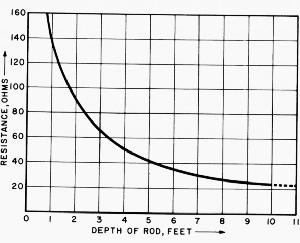
(2) Depth of Ground Rod:
- As per NEC code minimum ground electrode length of 2.5 meters (8.0 feet) to be in contact with the soil. * Doubling depth of Rod theoretically reduces resistance 40%. * Earthing Spike (electrodes) deeper is a very effective way to lower Earthing resistance. * Actual reduction of resistance depends on soil resistivity encountered in multi-layered soils. * The resistance decreases rapidly as the length of the electrode increases and less rapidly as the diameter increases.
(3) Spacing of Ground Rod:
- Earth resistance decrease when distance between adjustments earthing Rod is twice the length of the rod in Ground (in good soil).
t
Probe Spacing Probe distance (m) Soil resistance, Re (Ω) Soil resistivity, ρρ (Ω m) 0.3 14.75 27.79 0.6 7.93 29.88 0.9 6.37 36.00 1.2 4.36 32.86 1.5 4.31 40.60
(4) No of Ground Rods:
- Using multiple ground electrodes provides another way to lower ground resistance. * More than one electrode is driven into the ground and connected in parallel to lower the resistance. * The spacing of additional rods must be at least equal to the depth of the driven rod. * Two well-spaced rods driven into the earth provide parallel paths and act as two resistances in parallel. However the rule for two resistances in parallel does not apply exactly so the resultant resistance is not one-half the individual rod resistances. * The reduction in Earth resistance for equal resistance rods is * 40 % for 2 rods * 60 % for 3 rods * 66 % for 4 rods
(5) Material & Surface Condition of Ground Rod:
- Ground…