


Methods of Earth Resistance Testing (Part-2)
METHODS OF EARTH RESISTANCE TESTING (PART-2)
CAN WE USE AN MEGGER OR MULTIMETER FOR EARTH RESISTIVITY TESTING
- We cannot use Megger or Mulitimeter for Earth resistivity Testing.
Insulation Tester (Megger):
- Insulation testers are designed to measure at the opposite end of the resistance by inserting high DC Voltage. * Insulation testers use high test voltages in the kilovolt range. The area between electrode and ground is charged with high DC Voltage and we do not want grounds that measure in megohms. * Ground testers use Low Voltage for testing for operator safety, to low voltages.
Multimeter:
- However, a Multimeter or continuity test can use very low Voltage between an installed electrode and a reference ground, which is assumed to have negligible. * Low voltage DC can produce a resistance reading between ground and an earth electrode but it is not an accurate measurement. * Multimeter measurement may not be reliable, since reading can be influenced by soil transients, the electrical noise that is generated by utility ground currents trying to get back to the transformer, as well as other sources.
CAN EARTH RESISTANCE REDUCE BY POURING WATER AROUND TEST EARTH PROBE
- By pouring water is near test probe reduce contact resistance of between probe and ground at some extent. * If there is sufficient contact between probe and ground then pouring water near test probe is never decrease earth resistance of the system. * Earth resistance is the resistance of the ground electrode that is being measured, not that of the test probe. The Test probe is a tool to use measurement of earth resistance. * If the test setup has adequate spacing, the probes will be far enough away outside of the electrical field of the test ground so that watering them has no influence on the test result.
TEST METHODS FOR MEASURING EARTH RESISTANCE
There are six basic test methods to measure earth resistance
- Four Point Method (Wenner Method) 2. Three-terminal Method (Fall-of-potential Method / 68.1 % Method)) 3. Two-point Method (Dead Earth Method) 4. Clamp-on test method 5. Slope Method 6. Star-Delta Method
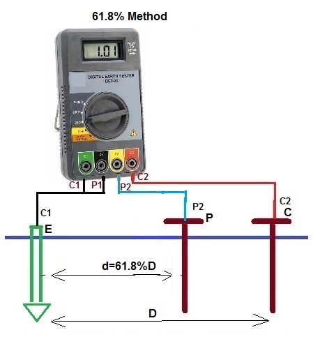
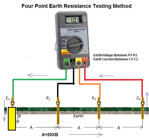
(1) FOUR POINT METHOD (WENNER METHOD):
- This method is the most commonly used for measuring soil resistivity,
Required Equipments:
- Earth Tester (4 Terminal) * 4 No’s of Electrodes (Spike) * 4 No’s of Insulated Wires * Hammer * Measuring Tap
Connections:
- First, isolate the grounding electrode under measurement by disconnecting it from the rest of the system. * Earth tester set has four terminals, two current terminals marked C1 and C2 and two potential terminals marked P1 and P2. * P1 = Green lead, C1 = Black lead, P2 = Yellow lead, C2 = Red lead * In this method, four small-sized electrodes are driven into the soil at the same depth and equal distance from one another in a straight line. * The distance between earth electrodes should be at least 20 times greater than the electrode depth in ground. * Example, if the depth of each earth electrode is 1 foot then the distance between electrodes is greater than 20 feet. * The earth electrode under measurement is connected to C1 Terminal of Earth Tester. * Drive another potential Earth terminal (P1) at depth of 6 to 12 inches from some distance at C1 Earth Electrode and connect to P1 Terminal of Earth Tester by insulted wire. * Drive another potential Earth terminal (P2) at depth of 6 to 12 inches from some distance at P1 Earth Electrode and connect to P2 Terminal of Earth Tester by insulted wire. * Drive another Current Electrode (C2) at depth of 6 to 12 inches from some distance at P2 Earth Electrode and connect to C2 Terminal of Earth Tester by insulted wire. * Connect the ground tester as shown in the picture.
Testing Procedure:
- Press START and read out the resistance value. This is the actual value of the ground Resistance of the electrode under test. * Record the reading on the Field Sheet at the appropriate location. If the reading is not stable or displays an error indication, double check the connections. For some meters, the RANGE and TEST CURRENT settings may be changed until a combination that provides a stable reading without error indications is reached. * The Earthing Tester has basically Constant Current generator which injects current into the earth between the two current terminals C1 (E) and C2 (H). * The potential probes P1 & P2 detect the voltage ΔV (a function of the resistance) due to the current injected in the earth by the current terminals C1 & C2. * The test set measures both the current and the voltage and internally calculates and then displays the resistance. R=V/I * If this ground electrode is in parallel or series with other ground rods, the resistance value is the total value of all resistances. * Ground resistance measurem…