
Methods of Earth Resistance Testing (Part-3)
METHODS OF EARTH RESISTANCE TESTING (PART-3)
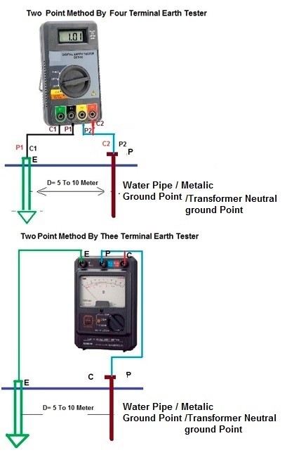
(3) TWO POINT (DEAD EARTH) METHOD.
- This method is used where the driving of ground spike is neither practical nor possible * To perform this test we have access to a good known ground such as an all metal water pipe. The water pipe should be extensive enough and be metallic throughout without any insulating couplings or flanges. * This method is not as accurate as three-point methods (62% method), as it is particularly affected by the distance between the tested electrode and the dead ground or water pipe
Required Equipment:
- Earth Tester (4 Terminal or 3 Terminal) * 2 No’s of Insulated Wires * Hammer
Connections:
- In This method, the resistance of two electrodes in a series is measured by connecting the P1 and C1 terminals to the ground electrode under test; P2 and C2 connect to a separate all-metallic grounding point like a water pipe or building steel. * The earth electrode under test must be far enough away from the secondary grounding point to be outside its sphere of influence.
Testing Procedure:
- Press START and read out the resistance value. This is the actual value of earthing resistance of the ground electrode under test. * Record the reading on the Field Sheet at the appropriate location. If the reading is not stable or displays an error indication, double check the connections. * Two terminals testing of earth resistance is appropriate for most general purpose testing in normally conductive soil. * Two terminal measurements include less test lead and contact resistance in the measurement and the result will be a reading slightly higher than the true earth resistance. * When measured results are higher than desired or if measurement directives require multi terminal techniques, switch to the 3 or 4 terminal techniques as needed.
1
Advantage:
- It does Not Require Disconnecting Equipment * This is the simplest way to obtain a ground resistance reading. * It is most effective for quickly testing the connections and conductors between connection points. * Required Less Test Lead. * Required small area for Measurement.
Disadvantage:
- This is not as accurate as the three-point method and should only be used as a last resort. * Non-metallic (high resistance) return Resistance areas should not overlap.
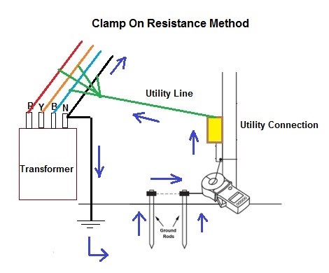
(4) CLAMP-ON TEST METHOD
- For the clamp-on method to be effective there must be a complete grounding circuit in place. The tester measures the complete resistance path (loop) that the signal is taking. All elements of the loop are measured in series. * The Induced Frequency testing or commonly called the “Clamp-On” test is one of the newest test methods for measuring the resistance-to-ground of a grounding system or electrode. * This is Convenient, Quick ,easy and safe Method * It does Not Require Disconnecting Equipment
Required equipment:
- Clamp-on Ground Resistance Meter. * 2 No’s of Insulated Wires
Connections setup:
2
Testing Procedure:
- Press START and read out the resistance value. This is the actual value of earthing resistance of the ground electrode under test. * The clamp-on methodology is based on Ohm’s Law (R=V/I). * The source coil inside the clamp of the earth tester inducing the voltage. This voltage is inductively applied to a complete circuit .The resulting current flow in the earthing circuit due to the induced voltage is measured by the current coil installed in the same clamp of the earth tester. * The resistance of the circuit can then be calculated by taking the ratio of the induced voltage and the circulated current in the earthing circuit. * It has to be ensured that the earthing system under test is included in the current circulation loop. The clamp-on earth tester measures the resistance of the path traversed by the induced current. * All elements of the loop are measured in series. This method assumes that only the resistance of the earthing system under test contributes significantly. * A low return path is required for readings. A high resistance return path will yield high readings.
Advantage
- There is no need to turn off the equipment power or disconnect the earth rod. * Not disconnecting the connections between the earthed body and the metal work of the electrical Earthing Point. * Not dangerous to human life because no any DC current injected in Probe.
Disadvantages:
- If the frequency of AC current injected into the earth by the tester is the same as that of disturbance current in the earth then accuracy of the readings are seriously affected. * The mutual inductance between the voltage and current loops of the clamp tester may affect accuracy of the readings. * The clamp-on method is only effective in situations with multiple earthing electrodes are in parallel and a closed circuit is available for the current circulation. * It cannot be used on isolated grounds, as there is no …