Site logo
Electrical Engineering Academy

9. Calculation of Crippling (Ultimate Transverse) Load on Electrical Pole

CALCULATION OF CRIPPLING (ULTIMATE TRANSVERSE) LOAD ON ELECTRICAL POLE

CALCULATION OF CRIPPLING (ULTIMATE TRANSVERSE) LOAD ON ELECTRICAL POLE

  • Wind Speed = 89 Mile/Hr. * Height of Pole=10 Meter * Type of Pole =RCC * Height of Pole in Ground=1.5 Meter. * Pole Section on Bottom of Pole (Length x Width)=400mm x 150mm * Pole Section on Top of Pole (Length x Width)=127mm x 150mm * Conductor Mounting from top of Pole(g)=0.5 Meter. * Distance between Two Pole(s) =20 Meter. * No of Conductor on Pole(n)=3No’s * Size of Conductor(r)= 30mm

CALCULATIONS:

  • Wind Pressure = 00256 x 2x Wind Speed * Wind Pressure = 00256 x 2x 90 = 20.506 Pound /Sq.Foot * Wind Pressure(Wp) =4.882×20.506 = 100 Kgf/M2 * Wind Load on Conductor/Span(ws)=2/3 x Wp x s x r x n * Wind Load on Conductor/Span(ws)=2/3 x 100 x 20 x 30 x 3 =120 Kg———–(I) * Height of Pole Above Ground (h)= 10-1.5 =8.5 Meter * Total Bending Movement at Ground Level due to Wind Load on All Conductor=ws x h * Total Bending Movement at Ground Level due to Wind Load on All Conductor(b)=120 x 8.5= 960 Kg.Mt * Equivalent Safe Working Load at said Meter from TOP of The Pole corresponding to Wind Load on All Conductors =b / (h- g) = 960 / 8.5-0.5 =120 Kg * Wind Load on Pole Surface above Ground Level (p1)=Wp x h /((l1+w1)/(2×1000)) * Wind Load on Pole Surface above Ground Level (p1)=100×8.5/(400+150/2×1000) =233.75 Kg * Centre of Gravity of Tapering rectangular section of Pole(p2)= (h/3)x((l2+(l1*2))/(l1+l2)) * Centre of Gravity of Tapering rectangular section of Pole(p2)= (5/3)x((127+(400×2)) /(127+400))=4.98Mt * Bending Movement at Ground Level due to Wind Load on Pole(p) =p1 x p2 * Bending Movement at Ground Level due to Wind Load on Pole(p) =233.75×4.98=1164.98 Kg.Mt * Equivalent Safe Working Load at said meter from Top of The Pole corresponding to Wind Load on Pole(wt) = p /(h-g) =1164.98 / (8.5-0.5) = 62 Kg——————————(II) * Total Transverse Load at said meter from Top of The Pole (Due to wind Load on Conductors + Wind Load on Pole Surface) (T)=Ws + Wt = 120+145.62 =256.62 Kg

Type of Pole Safety Factor Wooden Pole 3.5 RCC Pole 2.5 PCC Pole 2.5 Steel Tubular Pole 2 Rail/RSJ Pole 2 Struts (Steel Pole) 2.5 Struts (RCC/PCC) 3 PCC Pole for 33 KV 2

  • From Above Table Safety Factor=2.5 * Total Transverse Load (Crippling Load) of Pole = T x Safety Factor * Total Transverse Load (Crippling Load) of Pole = 256 x 2.5 =664 Kg. * Total Transverse Load (Crippling Load) of Pole=664 Kg

Max. Length of Pole (Meter) Min. Ultimate Transverse Load from 0.6meter from Top (Kg) 17 3000 17 2300 17 2000 17 1400 16 1100 15 1050 14 1050 13 1000 12 800 11 600 10 500 9 300 8 200 7 200 6 200 5 150 4 150 3 150

  • From Above Table Min. Ultimate Transverse Load for 10 Meter Pole = 500 Kg and as per our calculation it is 664 Kg hence Selection of Pole if O.K

Results:

  • Calculated Transverse Load (Crippling Load) of Pole = 664 Kg
Cover image
(7) OTHERS:

10. Calculate Size of Lift Pressurization Fan for Highrise Building

CALCULATE SIZE OF LIFT PRESSURIZATION FAN FOR HIGHRISE BUILDING

June 22, 2025 1 Comment

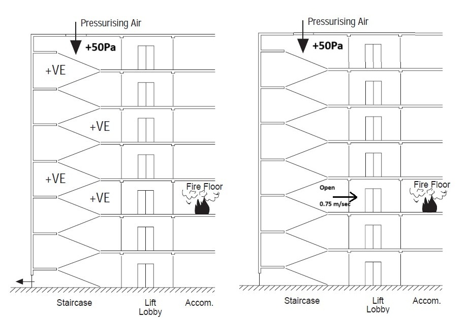
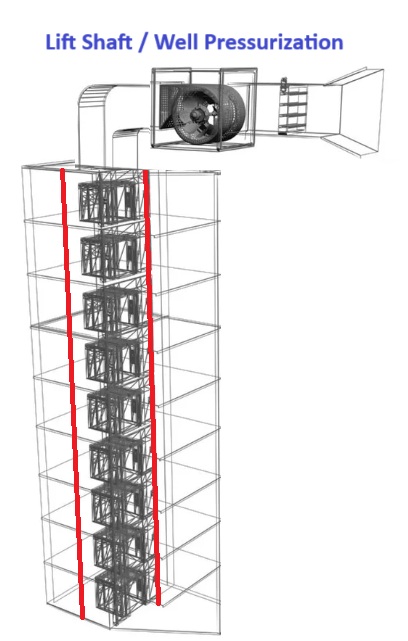
Calculate Size Lift Well Pressurization Fan having following Details

  • Type of Building is Commercial and Sprinkler Protected * Number of Lift Door (Basement to Terrace) is 17 Nos (B+G+15) * Lift Shaft width is 3600mm and Length is 3600mm * Lift Shaft height is 45 Meter * Vent window Size at Top of Lift Shaft is 320mm to 320mm * Lift Door width is 1 meter and Height is 1.2 meter. * No of Lift Door is 17 Nos * No of Floor door (Single Leaf) is 26 Nos * Air Velocity across door is 0.75 m/sec

CALCULATION:

  • Air Leakage are calculated on following areas
  1. Leakages through Door on each Floor 2. Leakages through lift Doors, Shafts, Vents 3. Leakages through External Wall, Floors 4. Open Lift Door

(1) LEAKAGES THROUGH DOOR ON EACH FLOOR

  • No of Floor door (Single Leaf) is 26 Nos * Leakage Area around the Door as per BS:5588 = 0.01m2

Air Leakage Data for Doors (BS 5588: Part-4)

Type of Door

Leakage Area (m2)

Single Leaf Doors in Frame Opening into Pressurized Space

0.01

Single Leaf Doors in Frame Opening Outwards

0.02

Double Leaf Doors with or without Central Rebate

0.03

Lift Door

0.06

  • Total leakage area all doors on all floors (A1): No of Door x Leakage area around Door * Total leakage area all doors on all floors (A1):26 x 0.01 * Total leakage area all doors on all floors (A1):0.26 m2

(2) LEAKAGES THROUGH LIFT DOORS, SHAFTS, VENTS

(a) Leakage through Lift Shaft:

  • Lift Shaft Wall Perimeter = 2 x (Lift Shaft Width + Lift Shaft Length) * Lift Shaft Wall Perimeter =2 x (3.6+3.6) * Lift Shaft Wall Perimeter =14.4 Meter * Leakage Area through Lift Shaft = Lift Shaft Perimeter x Lift Shaft Height * Leakage Area through Lift Shaft =14.4 x 45 * Leakage Area through Lift Shaft =648.8 Meter * Leakage Area Ratio for Lift Shaft: (A/Aw) =0.00084 as per NFPA 92A

Typical Leakage Area for Walls & Floors for Commercial Buildings (NFPA-92A)

Construction

Wall Tightness

Area Ratio

Exterior Building Wall (Including Construction Cracks but not around window & doors)

Tight

0.00005

Average

0.00017

Loose

0.00035

Very Loose

0.0012

Staircase Wall (Including Construction Cracks but not around window & doors)

Tight

0.000014

Average

0.00011

Loose

0.00035

Lift Shaft Wall (Including Construction Cracks but not around window & doors)

Tight

0.00018

Average

0.00084

Loose

0.0018

Floor (Including Construction Cracks but not around window & doors)

Tight

0.0000066

Average

0.000052

Loose

0.00017

  • Effective leakage Area (a)= Leakage Area Ratio for Lift Shaft x Leakage Area through Lift Shaft. * Effective leakage Area (a)= 0.00084 x 648.8 * Effective leakage Area (a)=0.544 m2

(B) LEAKAGES THROUGH LIFT DOORS

  • No of Lift Door =17 Nos * Leakage Area around the Lift Door as per BS:5588 = 0.06m2 * Leakage area around lift doors (b): No of Lift Door x Leakage around Lift Door * Leakage area around lift doors (b): 17 x 0.06 * Leakage area around lift doors (b): 1.020 m2

(C) LEAKAGE THROUGH VENT AT THE HEAD OF THE SHAFT

  • Vent Window Area (At the head of the shaft)(c) = Vent window width x Vent window height * Vent Window Area (At the head of the shaft) (c) = 0.320 x 0.320 * Vent Window Area (At the head of the shaft) (c) =0.102 * Total Leakage Area (A2) = (a)+(b)+(c) * Total Leakage Area (A2) = 0.544+1.020+0.102 * Total Leakage Area(A2) =1.667 m2 * Effective Leakage Area (Ae)= A1 x A2 / (A12 + A22)0.5 * Effective Leakage Area (Ae)= 0.26 x 1.667 / (0.26 + 1.667) 0.5 * Effective Leakage Area (Ae)= 0.257 m2

(4) OPEN LIFT DOORS

  • No of Open Lift Door = 2 Nos * Lift Door Area = Lift Door Width x Lift Door Height * Lift Door Area = 1.0 x 1.2 * Lift Door Area =2.2 m2 * Open Lift Door Area = No of Open Lift Door x Lift Door Area * Open Lift Door Area = 2 x 2.2 * Open Lift Door Area = 4.4 m2 * Velocity through Open Door = 0.75 meter/sec (*As per BS 5588: Part-4) * Air Flow through open doors = Air Velocity x Open Lift Door Area * Air Flow through open doors = 0.75 x 4.4 * Air Flow through open doors =3.3 m3/sec

CALCULATE AIR FLOW FOR LIFT WELL PRESSURIZATION

  • Air Flow for Lift Well Pressurization = 0.839 x Ae x (ΔP)1/2 * Minimum Design Pressure difference for Lift well pressurization (ΔP) = 50pa (*As per BS 5588) * Minimum Design Pressure difference for Lift well pressurization (ΔP) = 50pa (*As per NBC 2016) * Minimum Design Pressure difference for Lift well pressurization (ΔP) = 10pa (*As per NFPA 92A) * Consider Design Pressure difference for Lift well pressurization (ΔP) = 50pa

The pressure difference AS per NBC-2016 (Clause 4.4.2.5)

Enclosed Lobbies (or corridors)

25 to 30 Pa

Lift Shaft

50 Pa

Staircases

50 Pa

Enclosed staircase adjacent to such lobby (or corridors)

50 Pa

Enclosed staircases adjacent to non-pressurized lobby (or cor…

Cover image
(7) OTHERS:

11. Calculate Size of Staircase Pressurization Fan for Highrise Building

CALCULATE SIZE OF STAIRCASE PRESSURIZATION FAN FOR HIGHRISE BUILDING

May 25, 2025 Leave a comment

Calculate Size of Staircase Pressurization Fan having following Details

  • Building Height is 49 Meter * No of Staircase Door is 14 No’s * No of Fire Escape Door is 1 No at ground Floor * Staircase Door is 0.9 meter width and 2 meter height * Door is single Leaf and opening at Staircase (Pressurization) Side * Air Velocity across door is 0.75 m/sec

CALCULATION:

(1) AIR VOLUME REQUIRED WHEN ALL DOORS ARE CLOSED:

  • Design Pressure differential Level as per building height is as under

Pressure Level

Building Height (meter)

Fire Pressure (Pa)

Wind Stack Effect (Pa)

Design Pressure (Pa)

0

8.5

8

25

5

8.5

8

25

25

8.5

10.5

25

50

8.5

13

50

100

8.5

19.5

50

150

8.5

29.5

50

  • Air volume required when all doors are closed (Q1) = 0.827 x AE x P(1/n) * Where AE = Leakage Area from the space (m2) * P =Pressure Differential * n=Leakage Factor * As per above Table considering Air Pressure differential (P) = 50 Pa * As per following Table Single Leaf Doors in Frame Opening into Pressurized Space =0.01 m2

Type of Door

Leakage Area (m2)

Single Leaf Doors in Frame Opening into Pressurized Space

0.01

Single Leaf Doors in Frame Opening Outwards

0.02

Double Leaf Doors with or without Central Rebate

0.03

Lift Door

0.06

  • Here No of Staircase Door are 14 No’s * AE=Total Leakage Area = 0.01 x14 = 0.14 No’s * n=Leakage factor for Door is 2 as per following Table

Leakage Factor

n

Leakages area like Door

2

Leakages small area like window crack

1.6

  • Air volume required when all doors are closed (Q1) = 0.827 x AE x P(1/n) * Air volume required when all doors are closed (Q1) = 0.827 x 0.14x 50(1/2) * Air volume required when all doors are closed (Q1) =0.82 m3 / sec * It is assumed that there is other leakage, which are not calculated above is 50%. * Air volume required when all doors are closed (Q1) =0.82 X50% * Air volume required when all doors are closed (Q1) =1.23 m3/sec

(2) AIR VOLUME REQUIRED WHEN DOORS ARE OPENED:

  • Area of Staircase Door = Length x width = 2 x 0.9 * Area of Staircase Door (A)= 1.8 m2 * Air Velocity across door (V) is 0.75 m/s =148 fpm * It is assumed that Minimum Number of Opened Doors =Escape Door + 10% of remaining Doors. * Minimum Number of Opened Doors = 1 + (14×10%) = 1+2 * Opened Door Area = Escape Door Area + 50% of Remanning Door area * Opened Door Area = (1×1.8) + ((2×1.8) x50%) =1.8 +1.8 =3.6 m2 * Opened Door Area (A) =3.6 m2 * Air volume required when doors are opened (Q2) = A x V * Air volume required when doors are opened (Q2) = 3.6 x 0.75 * Air volume required when doors are opened (Q2) = 2.7 m3/sec

(3) TOTAL AIR SUPPLIED BY THE FAN:

  • Total Air Supplied = Air volume when doors are Closed+ Air volume when doors are opened * Total Air Supplied =Q1+Q2 * Total Air Supplied = 1.23 + 2.7 m3/sec * Total Air Supplied = 3.93 m3/sec * Total Air Supplied = 3.93 x 2113 * Total Air Supplied = 8300 CFM * Total Air Supplied per Floor = 8300/ 14 = 593 CFM

CONCLUSION:

  • Capacity of Staircase Pressurization Fan = 8300 CFM
Cover image
(7) OTHERS:

12. Calculate Size of Water Curtain Pump / Head of Fire Pumps / Pipe Size of Suction & Delivery Header.

CALCULATE SIZE OF WATER CURTAIN PUMP / HEAD OF FIRE PUMPS / PIPE SIZE OF SUCTION & DELIVERY HEADER.

April 3, 2025 1 Comment

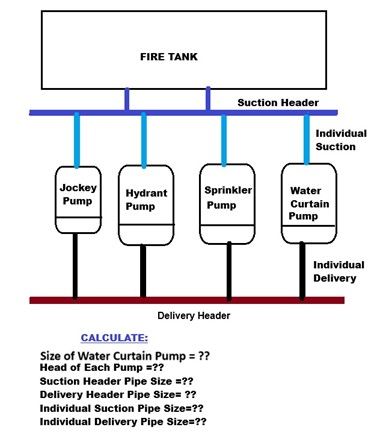
  • Calculate Size of Water Curtain Pump , Head of Fire Pumps along with Pipe size of Suction & Delivery Header.

CALCULATE SIZE OF WATER CURTAIN PUMP:

  • As Per water curtain requirement, required minimum pressure of 1.6 kg/sq.cm at the last nozzle of water curtain. * Total Length of Pipe Network for water curtain in one zone = 84 meter. * Spacing between Open Nozzle =2.5-meter Nozzle to Nozzle * Calculation: * No of Nozzle = Total Length of Pipe / Spacing between Nozzle * No of Nozzle = 84 / 2.5 = 34 Nos. * The flow through each nozzle Q = K x P (As per IS: 9972/ NFPA 13) * Where * Q = Flow in lpm flowing through nozzle * K = Nozzle Factor = 40 (As per manufacturer) * P = Total Pressure in Bar at flow Q = 1.6 bar * The flow through each nozzle Q = K x P =40 x 1.6 * The flow through each nozzle Q =64 LPM * Total Flow rate required= No Nozzle x Flow on Each Nozzle * Total Flow rate required= 34 x 64 * Total Flow rate required= 2176 LPM or 130.56 m3 /Hour * Maximum water curtain Pump capacity required= 2280 LPM or 137 m3/hour

CALCULATE PUMP HEAD FOR WATER CURTAIN PUMP:

  • Head requirement for Fire Pump has been decided as below * As Per water curtain requirement, required minimum pressure of 1.6 kg/sq.cm at the last nozzle of water curtain. * Calculate Total Length of Pipe: * Note: Considering that basement shall be provided the water curtain system: * Total Vertical Length of Pipe from Plant Room to remotest water curtain = 10 meter * Total Horizontal Length of Pipe from Plant Room to remotest water curtain= 50 meter * Total Length of Pipe from Plant Room to remotest water curtain = 50+10=60 meter * Equivalent Length of Pipe Due to Fittings @ 10 %= 6 meter * Total Length of Pipe = 65 meters * Calculate residual Head: * Required Residual head= Required minimum Pressure at last Point * Required Residual head= 1.6kg/sq.cm = 1.6×10.00=16 meters. * Calculate Head loss in Pipe: * Head Loss in bar (As per Hazen William’s formula) (H) = (6.05 x 10^5 x Q^85 x L) / (C^1.85 x d^4.87) * Where L = Length of pipe in meters * Q = Discharge in Lpm * C = Hazen-Williams roughness coefficients * D = Dia. of pipe in mm * H = Head loss in bar.

Pipe Material Hazen-Williams roughness coefficients (C) Cast Iron (unlined) 100 to 120 Cast Iron (lined) 130 Ductile Iron (cement lined) 140 Steel (new) 140 Steel (galvanized) 120 Copper 140 to 150 PVC and Plastic 140 to 150 Asbestos Cement 140 to 150 Concrete 100 to 140 Corrugated Metal 60 to 150 Riveted Steel 90 to 110 Vitrified Clay 110 to 140

  • Here L = 65 m * Q = 1280 Lpm * C = 120 (As per Table) * D = 150 mm * Head Loss in bar (H) = 6.05 x 10^5 x 2280^85 x 65 / 120^1.85 x 150^4.87 * Head Loss in bar (H) = 0.23 bar or 2 meters * Calculate Total Head of Water Curtain Pump: * Total Head of Pump = Static Head (Vertical) + Residual Head + Head loss in Pipe * Total Head of Pump = 10+16 + 2 =28 meter * Total Head of Pump =30 meter

CALCULATE PUMP HEAD FOR HYDRANT PUMP:

  • Head requirement for Fire Pump has been decided as below * As Per NBC Rule, there shall be minimum pressure of 3.5kg/sq.cm at the highest Fire Hydrant * Calculate Total Length of Pipe: * Total Vertical Length of Pipe from Plant Room to remotest Fire Hydrant = 64 meter * Total Horizontal Length of Pipe from Plant Room to remotest Fire Hydrant= 80 meter * Total Length of Pipe from Plant Room to remotest Fire Hydrant = 64+80=144meter * Equivalent Length of Pipe Due to Fittings @ 10 %= 158.4 meter * Total Length of Pipe = 159 meters * Calculate residual Head: * Required Residual head= Required minimum Pressure at last Point * Required Residual head= 3.5kg/sq.cm = 35 meters. * Calculate Head loss in Pipe: * Head Loss in bar (As per Hazen William’s formula) (H) = (6.05 x 10^5 x Q^85 x L) / (C^1.85 x d^4.87) * Where L = Length of pipe in meters * Q = Discharge in Lpm * C = Hazen-Williams roughness coefficients * D = Dia. of pipe in mm * H = Head loss in bar.

Pipe Material Hazen-Williams roughness coefficients (C) Cast Iron (unlined) 100 to 120 Cast Iron (lined) 130 Ductile Iron (cement lined) 140 Steel (new) 140 Steel (galvanized) 120 Copper 140 to 150 PVC and Plastic 140 to 150 Asbestos Cement 140 to 150 Concrete 100 to 140 Corrugated Metal 60 to 150 Riveted Steel 90 to 110 Vitrified Clay 110 to 140

  • Here L = 159 m * Q = 2850 Lpm * C = 120 (As per Table) * D = 150 mm * Head Loss in bar (H) = 6.05 x 10^5 x 2850^85 x 159/ 120^1.85 x 150^4.87 * Head Loss in bar (H) = 0.85 bar or 9 meter * Calculate Total Head of Fire Pump: * Total Head of Pump = Static Head (Vertical) + Residual Head + Head loss in Pipe * Total Head of Pump = 64+35 + 9 =108 meter * Total Head of Pump =110 meter

CALCULATE SIZE OF COMMON SUCTION HEADER:

  • There are 4 Nos …

13. Calculate Diesel Generator Protection Setting

CALCULATE DIESEL GENERATOR PROTECTION SETTING

March 6, 2025 Leave a comment

Recommended Generator Protection are

Recommended Generator Protection

ANSI Code

Protection Function

27

Under Voltage

32

Reverse Power 37

Under Power

40

Loss of Excitation 46

Negative Phase Sequence /Un Balance Load

49T

Thermal Overload 50

Instantaneous Over Current

51

Time grade Over Current 51G

Earth Fault Time Overcurrent

50/51V

Voltage Restrained Overcurrent 59

 Over voltage

60G

 Fuse Failure Monitor 64S

Stator Earth Fault Protection

81

Under / Over Frequency 87

Three Phase Current Differential

87N

Neutral Current Differential

87G

Generator Differential Protection

24G

Over excitation (Volt/Hertz) Protection

21G

Impedance Protection 59N or 64G1

Stator EF protection (0-95%)

27TN or 64G2

Stator EF protection (100%) 50BF

Breaker Failure Protection

24G

Over excitation (Volt/Hertz) Protection

78G

Pole slip protection

PROTECTION SETTING CALCULATION:

(1) UNDER VOLTAGE RELAY (27):

  • The Under Voltage Relay measure either phase-to-phase (Ph-Ph) or phase-to-neutral (Ph-N) fundamental RMS voltage depending on the input voltage setting. If the value of measured voltages deviates from the setting values, then these relays will give a trip indication. * Reason: * An under-voltage condition in a diesel generator can occur due to several reasons, overloading the generator beyond its capacity, faulty Automatic Voltage Regulator (AVR), issues with the stator windings, problems with the voltage sampling line, loose connections, low engine speed, fuel problems, and issues with the excitation system * Setting: * The Typical under-voltage setting is usually 80 % of the normal rated voltage. If the voltage falls below this level for the set amount of time, then the tripping command is issued by the relay and hence the system is isolated. The time setting is used to avoid tripping due to any transient disturbances. the exact setting can vary depending on the specific generator and system requirements. * Usually, motors stall at below 80% of their rated voltage. An under-voltage element can be set to trip motor circuits once fall below 80% so that on the restoration of supply an overload is not caused by the simultaneous starting of all the motors. * Normally Generators are designed to operate continuously at minimum voltage of 95% of its rated voltage. * Two levels of tripping are provided depending on the severity of the condition, these under voltage elements are blocked from tripping when the generator breaker is open to allow for startup conditions. * Calculation: * For 415V Diesel Generator * Level 1 (Slow)= 80% of Rated Voltage * Level 1 (Slow)= 80% x 415V =332 V * Time Delay = 5 sec. * Level 2 (Fast): 70% of Rated Voltage * Level 2 (Fast)= 70% x 415V =290 V * Time Delay = 0 sec.

(2) Over Voltage Protection [59]:

  • The Over Voltage Relay measure either phase-to-phase (Ph-Ph) or phase-to-neutral (Ph-N) fundamental RMS voltage depending on the input voltage setting. If the value of measured voltages deviates from the setting values, then these relays will give a trip indication. * Reason: * System over voltages can damage the insulation of components. Over voltages occur due to sudden loss of load, improper working of tap changer, Generator AVR malfunction, Reactive component malfunctions, etc. * Setting: * The Overvoltage setting is usually 110 to 130 % of the normal operating voltage depending on the system requirement. * If the voltage rises above this level for the set amount of time then the tripping command issued by the relay and hence the system is isolated. The time setting is used to avoid tripping due to any transient disturbances. * Calculation: * For 415V Diesel Generator * Level 1 (Slow)= 110% of Rated Voltage * Level 1 (Slow)= 110% x 415V =456 V * Time Delay = 5 sec. * Level 2 (Fast): 130% of Rated Voltage * Level 2 (Fast)= 130% x 415V =539 V * Time Delay = 0 sec.

(3) REVERSE POWER PROTECTION [32R]:

  • Reverse power relay is an electronic, microprocessors-based protection device which is used for monitoring and stopping the power supply flowing grid side to the DG side or generator running in parallel with another generator. If accidentally leakage current is received by generator, then it can start to running as motor. This situation may be very dangerous for generator set. * The function of the reverse power relay is to prevent a reverse power condition in which power flows from the bus bar into the generator. * This condition can occur when there is a failure in the prime mover such as an engine or a turbine which drives the generator. * Relay detects the reverse flow of power from the load back to the generator, which can occur during system faults or abnormal operating conditions. By sensing this reverse power flow, the relay triggers a protective action, typically disconnecting …
(7) OTHERS:

14. Calculate Main Fire Pump Capacity with Head and other Characteristic as per NBC 2016 / IS 12469 / IS 15301.

CALCULATE MAIN FIRE PUMP CAPACITY WITH HEAD AND OTHER CHARACTERISTIC AS PER NBC 2016 / IS 12469 / IS 15301.

January 31, 2025 1 Comment

EXAMPLE:

Calculate Main Fire Pump Capacity with Head and other characteristic as per NBC 2016 / IS 12469 / IS 15301 for following Details.

  • Type of Hazard: * Fire Type is Light hazard * Fire Protection Area (Building) Detail: * There are 4 Nos of Residency Building having 12 Nos floor and each floor have of 3.2 Meter height. (Building Height 38.40 Meter). * Fire Fighting Pipe Network Detail: * The maximum horizontal length of fire System header is 50 Meter. * Up to Furthest Location in Fire Network System, the maximum bend in Horizontal Line are 6 Nos and Vertical Line /Header are 2 No. The Losses on each bend is 1.5 to 2 Meter. * The Water Friction losses are approximately 3%

CALCULATION:

  • We will derive calculation as per following sequence.
  1. Calculate Size of Main Fire Pump. 2. Calculate Head of Fire Pump. 3. Calculate RPM of Pump. 4. Calculate Pump Pressure. 5. Check Pump Characteristic as per Clauses.

(1) CALCULATE SIZE OF MAIN FIRE PUMP:

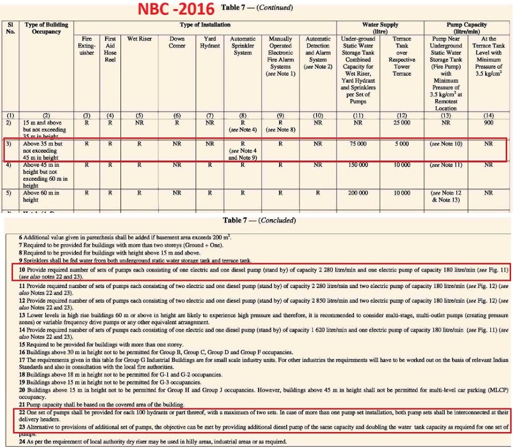
  • Type of Building occupancy is Residency and type of hazard is Light. The Building Height is 38.40 Meter. * AS PER NBC-2016: * As per NBC 2016, Table-7, Note No 10 , The Main Fire Pump Capacity will be 2850 Liter/Min.

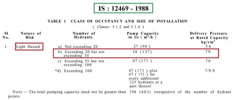
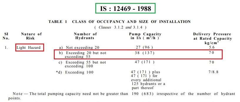
  • AS PER IS: 12469: * Total No of Hydrant for Building = 1 No for Each Floor, hence approximate 1×12 (Floor) x4 (Tower) =48 No’s, * As per IS 12469 , Fire Pump Capacity Shall be 137 M3/Hour = 2282 Liter / Min

  • From Above consideration Capacity Main Fire Pump Shall be 2850 Liter /Min.

(2) CALCULATE HEAD OF MAIN FIRE PUMP:

  • Vertical Head * Vertical Head =No floor x Floor Height * Vertical Head =12 x 3.2 = 38.40 Meter. * Head Losses due to Bend= 2 x Head Losses of Each Bend * Head Losses due to Bend= 2 x 1.5 = 2.06 Meter. * Equivalent Vertical Head=Vertical Head+ Head Loss due to bend * Equivalent Vertical Head=38.40+2.06 =40.46 Meter. * Total Vertical head= Equivalent Vertical Head x Friction Losses. * Total Vertical head= =40.46 x 1.03= 41.67 Meter——-(A) * Horizontal Head * Horizontal Head=Maximum Horizontal Length * Horizontal Head=50 Meter * Head Losses due to Bend= 6x Head Losses of Each Bend * Head Losses due to Bend= 6 x 1.5 = 9 Meter. * Equivalent Horizontal Head= Horizontal Head+ Head Loss due to bend * Equivalent Horizontal Head=50+9 =59 Meter. * Total Horizontal head= Equivalent Horizontal Head x Friction Losses. * Total Horizontal head= =59 x 1.03= 60.77 Meter——-(B) * Total Head: * Total Head =Horizontal Head + Vertical Head * Total Head =41.67+60.77= 102 Meter. * As per above Calculation Head for Fire Pump shall be 110 Meter.

(3) CALCULATE SPEED OF MAIN FIRE PUMP:

  • As per IS 15301: * As per IS 15301 (Clause 6.2) , Electric motors required to feed the pump up to 2280 Liter/Min are usually running at 2900 RPM and the pumps required to match the motors must also run at the same revolutions per minute. * As per above Consideration Fire Pump speed shall be 2900 RPM.

(4) CALCULATE MAIN FIRE PUMP PRESSURE:

  • As per IS 12469: * As per IS 15301 (Clause 6.2) , Fire Pump Delivery Pressure shall be 7.0 Kg/cm2 * As per above Consideration Fire Pump speed shall be 7.0 Kg/cm2.


 (5) Check Pump Characteristic as per Clauses.

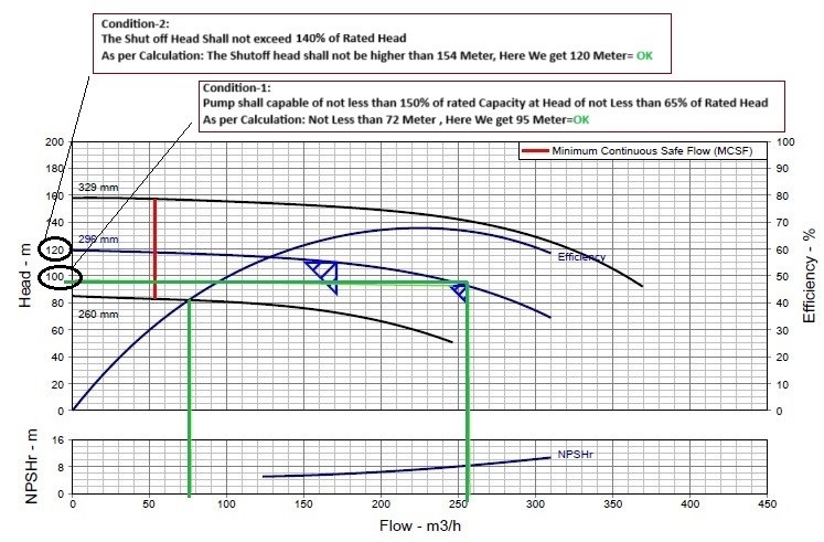
  • For Calculation consider Pump Flow rate 171 M3/Hour and head is 110 Meter. * As per IS 12469: * As per IS 12469 ,Following Two Condition shall be satisfied for Fire Main Pump. * Pump shall be capable of not less than 150% of rated Capacity at Head of not Less than 65% of Rated Head. * The Shut off Head Shall not exceed 140% of Rated Head. * Pump Graph for 171 m3/hour is as per following.

  • Condition-1: * Pump shall be capable of not less than 150% of rated Capacity at Head of not Less than 65% of Rated Head. * Pump Shall be capable to supply =150% of rated Capacity * Pump Shall be capable to supply =150% x 171 = 256.5 M3/Hour. * Pump shall capable of Head not less than=65% of Rated Head * Pump shall capable of Head not less than=65% x 110 = 72 Meter * As per Graph for flow rate of 256.5 M3/Hour Pump head is 95 Meter ( Which is less than 72 Meter) * Condition-1 is satisfied. * Condition-2: * The Shut off Head Shall not exceed 140% of Rated Head. * The Shut off Head Shall not higher =110×1.40 =154 Meter. * As per Graph for flow rate of 256.5 M3/Hour, shut off Pump head is 120 Meter (Which is less than 154 Meter) * Condition-2 is satisfied.

CONCLUSION:

  • Size of Main Fire Pump: 2850 Liter/Min * Head of Fire Pump: 110 Meter. * RPM of Pump & Motor: 2900 RPM * Calculate Pump Pressure: 7.0 Kg/cm2 * Check Pump Characteristic as per Clauses: …

15. Calculate Size of Anchor Fastener for Cable Tray Support.

CALCULATE SIZE OF ANCHOR FASTENER FOR CABLE TRAY SUPPORT.

April 28, 2024 1 Comment

Calculate Size of Anchor fastener for Cable Tray Support having following Details

  • CABLE TRAY DETAIL: * Size of Cable Tray=600mm Ladder Type Cable Tray * Weight of Cable Tray=120 kg/meter * CABLE DETAILS (LAID IN CABLE TRAY) * Size of Cable =3.5Cx300 Sq.mm, Alu, XLPE, Armored Cable * No of Cable / Cable tray= 6 No’s * Weight of Cable = 5.9 Kg/meter * Size of Cable =3.5Cx150 Sq.mm, Alu, XLPE, Armored Cable * No of Cable / Cable tray= 2 No’s * Weight of Cable = 4.5 Kg/meter. * CABLE TRAY SUPPORT DETAILS * Cable Tray Support installed at 1 Meter of Cable Tray * Weight of Cable Tray Support =5.8 Kg/meter * Safety Factor=5

CALCULATIONS

  • Weight of Cable Tray Support = No of Support X Weight of Support * Weight of Cable Tray Support =1×5.8 Kg/Meter * Weight of Cable Tray Support =5.8 Kg/Meter———(A) * Weight of Cable Tray = No of Cable Tray X Weight of Tray * Weight of Cable Tray =1×120 * Weight of Cable Tray =120 Kg/Meter———(B) * Weight of 3.5Cx300 Sq.mm Cable = No of Cable X Weight of Cable * Weight of 3.5Cx300 Sq.mm Cable =6×5.9 * Weight of 3.5Cx300 Sq.mm Cable =35.4 Kg/Meter———(C1) * Weight of 3.5Cx150 Sq.mm Cable = No of Cable X Weight of Cable * Weight of 3.5Cx150 Sq.mm Cable =2×4.5 * Weight of 3.5Cx150 Sq.mm Cable =9 Kg/Meter———(C2) * Total Weight =Safety Factor X (Weight of Cable Tray support + Weight of Cable Tray + Weight of Cables) * Total Weight =5X (5.8+120+35.4+9) Kg/Meter * Total Weight=851 Kg/Meter—————–(1) * Consider 4 No of 10mm size of Anchor Fastener having Basic Tensile Load Capacity of 5KN at each Support. * Total Tensile Load= No of Anchor Fastener X 101.97XAnchor Tensile Load Capacity (KN) * Total Tensile Load=4×101.97×5 * Total Tensile Load=1876 Kg/Meter————(2)

Here Total Tensile Load Capacity of Anchor Fastener (1876 Kg/Meter) > Total Weight (851 Kg/Meter) hence Size of Anchor Fastener is OK