Site logo
Electrical Engineering Academy
(5) Illumination / STREET LIGHT / FLOOD LIGHT:

8. Calculate Voltage drop for Street Light Poles

CALCULATE NO OF STREET LIGHT POLES

TYPICAL CALCULATION OF ROAD LIGHTING:

  • Luminaries are properly selected and mounted on a location most feasible and effective with minimum cost. For a 230 volts system, a voltage drop of 5% is allowed although in extreme cases 15% voltage drop is sometimes tolerated. 3

  • Street illumination level in Lux (E)=(Al x (cu x mf)) / (w x d) * E = The illumination in Lux * w = Width of the roadway * d = Distance between luminaries * cu = Coefficient of utilization. Which is dependent on the type of fixture, mounting height, width of roadway and the length of mast arm of outreach? * Al = Average lumens, Al = (E x w x d) / Cu x mf * The typical value of Al is * 20500 lumens for 400 watts * 11500 lumens for 250 watts * 5400 lumens for 125 watts * The value of Al varies depending upon the type of lamp specified. * mf : It is the maintenance factor (Normally 0.8 to 0.9)

 (1) CALCULATE LAMP WATT FOR STREET LIGHT POLE:

  • Calculate Lamp Lumen for street Light Pole having Road width of 7 meter, distance between two Pole is 50 meter, Maintenance factor is 0.9, Coefficient of utilization factor is 0.29, light pedestrian traffic is medium and Vehicular traffic is very light and Road is concrete road. Solution: From Above table Recommended of illumination (E) in Lux is 6.46 per sq. meter. w = 7.00 meters , d = 50 meters , mf = 0.9, cu = 0.29 To decide Lamp Watt It is necessary to calculate Average Lumens of Lamp (Al). * Average Lumen of Lamp (Al)=(E x w x d) / Cu x mf * Al=(6.46x7x50)/(0.29×0.9)= 8662.83 Average lumen Lamp lumen of a 250 watts lamp is 11,500 lm which is the nearest value to 8662.83 lumen. Therefore, a 250 watts lamp is acceptable. Let’s Computing for the actual illumination E for 250 Watt Lamp * Illumination (E)=(Al x (cu x mf)) / (w x d) * E= (11500×0.29×0.9) / (7×50) = 8.57 lumen per sq meter. Conclusion: Actual illumination (E) for 250 Watt is 8.57 lumen per sq meter which is higher than recommended illumination (E) 6.46.

  • HENCE 250 WATT GIVES ADEQUATELY LIGHTING.

 (2) CALCULATE SPACING BETWEEN TWO LIGHT POLES:

  • Calculate Space between Two Pole of Street Light having Fixture Watt is 250W , Lamp output of the Lamp (LL) is 33200 lumens , Required Lux Level (E) is 5 lux , Width of the road (W) = 11.48 feet (3.5 M),Height of the pole (H) = 26.24 feet (8 M) ,Coefficient of utilization (CU) = 0.18, Lamp Lumen Depreciation Factor (LLD) = 0.8 ,Luminaries dirt Depreciation Factor (LDD) = 0.9 Solution: * Luminaries Spacing (S) = (LLxCUxLLDxLDD) / (ExW) * Luminaries Spacing (S) = (33200×0.18×0.9×0.8) / (5×11.48)

  • LUMINARIES SPACING (S) = 75 FEET (23 METERS)

 (3) CALCULATION OF THE ALLOWED ILLUMINATION TIME:

  • The allowed illumination time in hours T = k.t.1000/E. * Where: k = extension factor * t = permissible time in hours at 1000 lux, unfiltered daylight * E = luminance (lx)

Extension Factor Lamp Extension Factor Incandescent lamps, 2.7 to 3.2 Halogen reflector lamps 2.5 to 3.5 Halogen capsules 2.5 to 3.5 High-pressure metal-halide 1.1 to 2.1 High-pressure sodium lamps 4 Fluorescent lamps 1.9 to 2.7

  • Example: * In sunlight (100000 lux) and extension factor 1: The permissible illumination time (T) =1 x 70 x 1000/100 000 = 0.7 hour. * In halogen light (200 lux) and extension factor 2.3: The permissible illumination time (T) = 2.3 x 70 x 1000/200 = 805 hours. * In UV-filtered halogen light (200 lux) and extension factor 3.5: The permissible illumination time (T) = 3.5 x 70 x 1000/200 = 1225 hours.

 (4) CALCULATE UNIFORMITY RATIO:

  • Once luminaries spacing has been decided It is necessary to check the uniformity of light distribution and compare this value to the selected lighting * Uniformity Ratio ( UR) = Eav /Emin * Eav= average maintained horizontal luminance * Emin = maintained horizontal luminance at the point of minimum illumination on the pavement

 (5) ENERGY SAVING CALCULATIONS:

  • At a simplistic level, the cost of running a light is directly related to the wattage of the globe plus any associated ballast or transformer. The higher the wattage, the higher the running cost and it is a straightforward calculation to work out the running cost of lamp over its lifetime: * Running cost = cost of electricity in $/kWh x wattage of lamp x lifetime in hours.

 CALCULATE LUX LEVEL FOR STREET LIGHTING

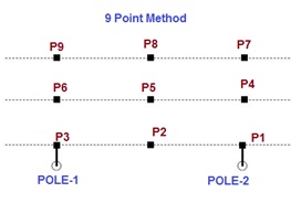
  • The Average Lux Level of Street Light is measured by 9 point method. Make two equal quadrants between two Street light poles. on the lane of light poles( one side pole to road). * We have 3 points P1,P2 and P3 under the light pole then P4 & P7 are points opposite pole 1 or Point P3 same is applicable for P6 and P9 for Pole 2. * The average lux = [(P1+P3+P7+P9)/16]+[(P2+P6+P8+P4)/8]+[P5/4]

 2
(5) Illumination / STREET LIGHT / FLOOD LIGHT:

9. Measurement of LUX Level and Uniformity at Indoor and Outdoor Lighting (Part-1)

MEASUREMENT OF LUX LEVEL AND UNIFORMITY AT INDOOR AND OUTDOOR LIGHTING (PART-1)

INTRODUCTION:

  • Working plane illuminance (Lux Level) need to be measured in the field for cross check of whether the existing installation meets a design requirement or not. * Field surveys may also be useful to identifying the causes of complaints about lighting, hence the results of field surveys may be useful for the designer, installers and end users. * There are various methods are developed for field measurement of Interior Lighting and External Lighting. * The Measurement Methods recommended by the various national lighting bodies are generally similar or slightly derivatives to each other. The most common method / Standard is BEE, CIBSE, IES and DIN code * The most of methods require to measurement of illuminance at points on a grid at working-plane height or at Floor, but the grid size and position of the measuring points may be differed from various standard to standard. * The IES method and its derivatives use the position of the grid according to the luminaire locations. * The CIBSE and DIN methods use a position of grid according to the room size. * The techniques of analysis of the field measurement results also differ

BASIC REQUIREMENTS FOR EXTERIOR & INTERIOR LIGHT LEVEL MEASUREMENT

  • The following Points should be considered for accurate measurement of interior and exterior lighting Lux level. * Where possible, use the same calibrated illuminance measurement meter (LUX Meter) If the same meter is not available, use the same make and model of calibrated meter to minimize error. * When taking measurements, verify that any objects/materials are not blocking any light to the meter head. The use of a remote meter head cabled to the meter body is recommended to prevent the operator from blocking the meter’s “view” of the lighting system being measured. * In Outdoor Lighting it is essential to measure of illuminance should be done in night (proper dark). * For indoor lighting, measurements with lights ON and Lights OFF technique can be followed and the daylight variation is not too much and the survey time is not too long. * In an installation of fluorescent discharge lamps, the lamps must be switched on at least 30 minutes before the measurement to allow for the lamps to be completely warmed up. * In many situations, the measuring plane may not be specified or even non-existent. Hence it is necessary to define measurement height, typically 0.8 to 1 meter from the ground or floor level. * The lux measurement procedure simply requires positioning a meter’s sensor on the surface or location where you wish to measure the incident light. * The sensor should face the light source at a right angle. If the sensor is not perpendicular to the light, the measurement will be incorrect, though some lux meters have a cosine correction to account for the angle. * Meters that require a colour correction factor may have a means of inputting the CCF to adjust the result for LEDs or fluorescent lights; otherwise, you will have to manually multiply the measured lux by the CCF.

 INDOOR ILLUMINATION (LUX LEVEL) MEASUREMENT.

 (1) AS PER ROOM INDEX METHOD (AS PER BEE CODE / CIBSE CODE):

  • This methos is more suitable where measuring Plan / Points for an interior is more rectangular than square. First, we need to be found Room Index. * Based on the room index, the minimum number of illuminance measurement points is decided by Room Index Number * Room Index (RI) = (L x W) / H x (L+ W) * Where L = Length of Room * W = Width of Room * H= Height of the luminaires above the plane of measurement 

Table 4-2: Number of points for measuring illuminance

Room index

Minimum number of measurement points

For ± 5% accuracy

For ± 10% accuracy

RI < 1

8

4

1 < RI < 2

18

9

2 < RI < 3

32

16

RI > 3

50

25

 Sample calculation

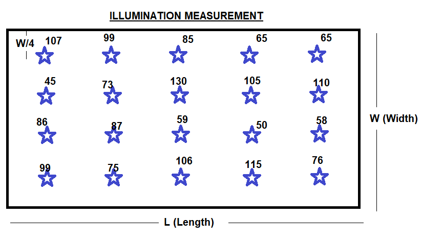
  • Measure Illumination Level of an office room have length, L = 7.5 m and width W = 5 m, * Solution: * Suppose Height of Illumination from Floor is 2 Meter * Room Index RI = (L x W) / H x (L+ W) * Room Index RI = (7.5 x 5) / 2 x (7.5+ 5) * Room Index RI = 1.5 * From Table 4.2 minimum Illumination Measure Points should be 18 No’s * The illuminance measurements Points with Measured Value in Lux are marked on the grid.

1

Measurement Reading Details

107 Lux

99 Lux

85 Lux

65 Lux

65 Lux

45 Lux

73 Lux

130 Lux

105 Lux

110 Lux

86 Lux

87 Lux

59 Lux

50 Lux

58 Lux

99 Lux

75 Lux

106 Lux

115 Lux

76 Lux

Min

45 Lux

Max

130 Lux

Average

85 Lux

U1=MIN/AVG

0.5 Lux

U2=MIN/MAX

0.3 Lux

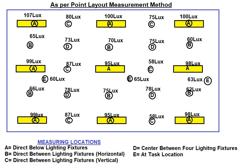
 (2) AS PER POINT LAYOUT METHOD

  • For office and other task areas, identify a set of measurements points on desktops and other work surfaces that best represents lighting conditions in the space. * It may not be possible to develop a uniform spacing grid, but points should be chosen that represent the various lighting c…
(5) Illumination / STREET LIGHT / FLOOD LIGHT:

10. Measurement of LUX Level and Uniformity at Indoor and Outdoor Lighting (Part-2)

MEASUREMENT OF LUX LEVEL AND UNIFORMITY AT INDOOR AND OUTDOOR LIGHTING (PART-2)

(3) AS PER DEUTSCH NORM DIN 5035

  • In this Method the working plane divide into a number of sections which are at least rectangular, of ratio of length to side not less than 1: 2 but which are preferably of square shape. * A square grid of minimum size 1 meter is established within each section with a measurement point at the centre of each square. * The grid module defining the measurement points is selected so as not to coincide with the luminaire grid in either principal direction. * In exceptionally large interiors the grid size may be up to 5 meters. there is not any mention of accuracy limits of the method, but this is not surprising given the flexibility which the user of the method is allowed in choice of grid size. * The DIN system is the only one of the three methods studied to give any advice concerning illuminance measurements in obstructed interiors. Areas of the working plane located between large obstructions are treated for measurement purposes as separate spaces.

1

OUTDOOR ILLUMINATION (LUX LEVEL) MEASUREMENT

 (1) NINE POINT METHOD FOR DETERMINING LUX LEVELS IN STREET LIGHTING

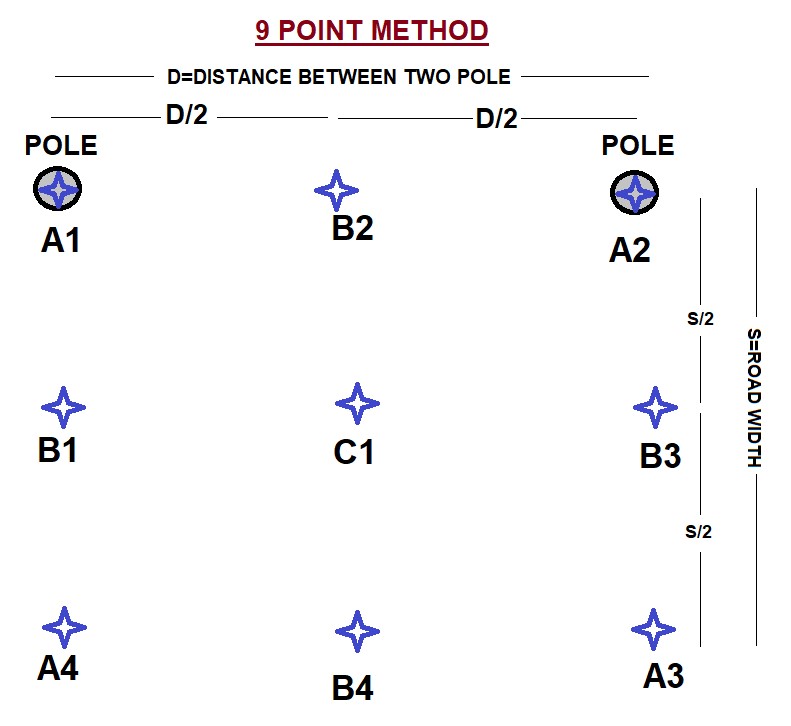
  • The Lux Level of Street Light is measured by 9-point method. * We need to make two equal quadrants between two light poles and between Pole and Rode edge. * Two Measuring Points below Light Pole (A1,A2) and Two opposite side of Pole at Road Edge (A3,A4). * Two Point between Pole and Road edge (B1,B3). * One Point Between Pole (B2) and on One Point between opposite side of Pole at road edge (B4) * One Point is at centre (C1). * Average Lux = (A1+A2+A3+A4)/16 + (B1+B2+B3+B4)/8 +C1/4

2

  • Solution

26 Lux 27 Lux 13 Lux 12 Lux 15 Lux 14 Lux 26 Lux 32 Lux 22 Lux

  • Average Lux = (A1+A2+A3+A4)/16 + (B1+B2+B3+B4)/8 +C1/4 * Average Lux = (26+26+13+22)/16 + (12+27+14+32)/8 +15/4 * Average Lux =20Lux 

MIN 12 Lux MAX 32 Lux AVG 20 Lux U1=MIN/AVG 0.58 U2=MIN/MAX 0.38

 (2) AS PER GRID POINT SET UP MEASUREMENT

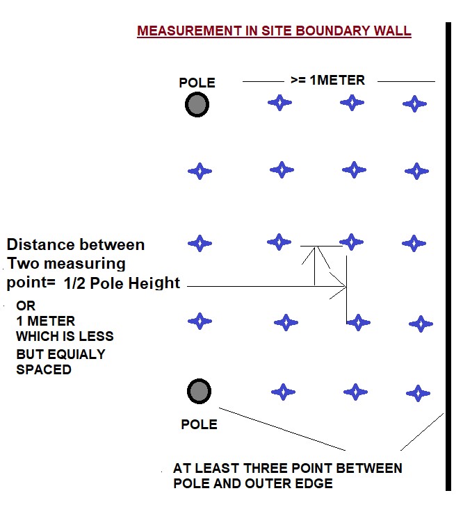
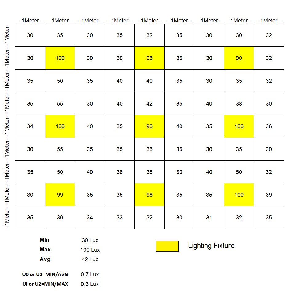
  • Identify a horizontal grid of measurement points on the Illumination Measurement site surface. Locate measurement points on gridlines covering the test measurement area. * Ensure that the spacing between measurement points is uniform in both directions and is less than one-half the pole height or less than 4.5 Meter, whichever is smaller. * For installations with lights spaced less than 4.5 Meter apart, locate measurement points no farther apart that one-half the pole height, with at least three points between poles in both directions. * Record the location of all measurement grids and point layouts with dimensions from surrounding poles or other structures. Provide this information, including a sketch or rendering of the grid layouts. * For open areas such as main parking, make the measurement grid large enough to cover at least four poles of this Area layout and at least two Pole are covered. * For site perimeter open areas or areas adjacent to a building edge establish the test area measurement grid in a typical perimeter or building edge area. The depth of the test area should extend from the paved site boundary or building edge inward to the nearest line of light poles that are at least 4.5 Meter from the boundary or building edge. * The width of the test area must cover at least two of the poles in the line that is at least 4.5 Meter from the boundary or building edge.

(A) IN OPEN AREA

3

(B) IN THE AREA OF SITE PERIMETER

4

(C) NEAR SITE BOUNDARY AREA:

5

(5) Illumination / STREET LIGHT / FLOOD LIGHT:

11. Measurement of LUX Level and Uniformity at Indoor and Outdoor Lighting (Part-3)

MEASUREMENT OF LUX LEVEL AND UNIFORMITY AT INDOOR AND OUTDOOR LIGHTING (PART-3)

(3) GRID METHOD TO MEASURE ILLUMINATION ON THE ROAD

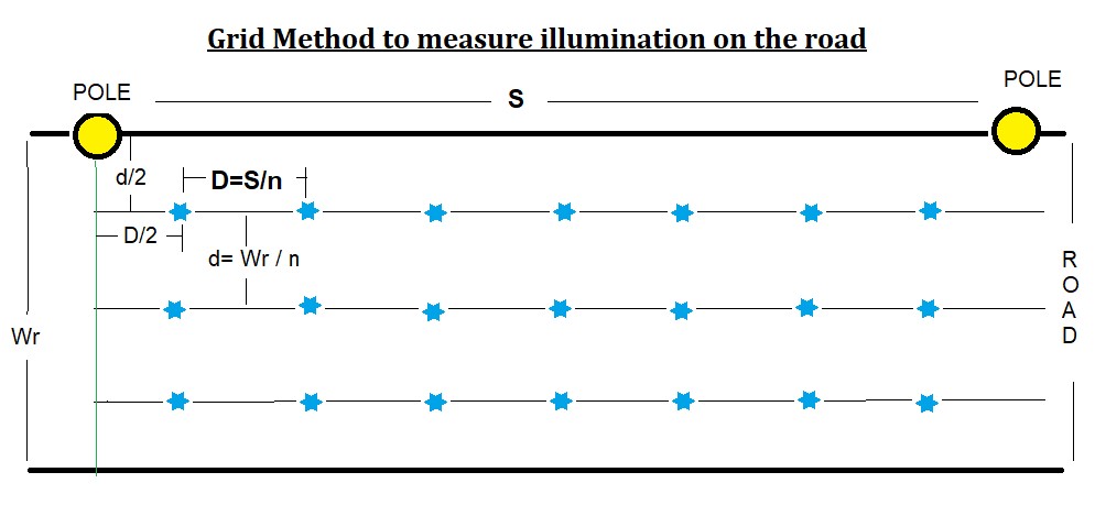
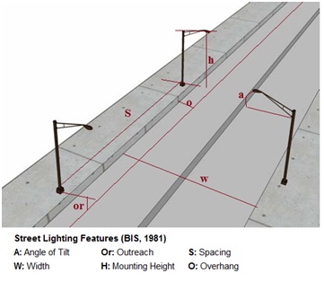
  • The arrangement of the measuring points depends on the distance between the Illumination Pole and the width of the Road. * The measurement of illuminance should be performed on the area in longitudinal direction two consecutive luminaires in the same row and in transverse direction the width of the area with the same illumination class, i.e. if the road and adjacent pavement or bicycle path have the same illumination class, they may be considered as one area during the measurements. The measuring points should be distributed evenly within the measuring field. * The distance between the measuring points (D in Meter) in the longitudinal direction should be calculated using the formula * The distance between the measuring point in longitude ( D)=S / N * where: S= the distance between the luminaires in [m], N= the number of measurement points in the longitudinal direction, for S ≤ 30 m, it is N = 10, for S > 30 m, the smallest integer giving D ≤ 3 m. * The distance between measurement points (d in Meter) in the transverse direction should be calculated with the formula: * The distance between the measuring point in transverse (d) = Wr / n * where: Wr= the width of the road or the area under consideration in Meter. * n = the number of measurement points in the transverse direction equal to 3 or more and being an integer giving d ≤ 1.5 m. * The distance between the points and the edges of the surface under consideration should be D/2 in the longitudinal direction and d/2 in the transverse direction. The location of the measurement points in the measuring field is shown in Figure.

1

(4) EQUAL SPACE METHOD

  • In this Method at least10 equal measuring Points are taken between two lighting Pole on one side of the Roadway. * These measurement points cannot be spaced more than 5 meters apart. Two lines of measurement points are needed per driving lane, one-half lane width apart. * Once you have taken all of your illuminance measurements, you can calculate an average illuminance for the section of roadway you have measured.

2

WHAT IS LIGHTING UNIFORMITY

  • light uniformity refers to the uniformity of lighting in an environment. It is necessary to maintain the uniformity of light in order to make sure that everything is perfectly visible in the room. * Uniformity is the ratio of the minimum lighting level to the average lighting level in a specified area. * U1 = E Min / E Average * U2 = E Min / E Maximum * U & E stands for uniformity & illuminance respectively. * Uniformity is a quality parameter for the overall illuminance distribution. * It is quite useful to use this uniformity ratio to describe how the lights are evenly distributed on the ground. If the difference between minimum and average lux is small, then the ratio is high, which gives better light uniformity. * The maximum lighting uniformity is 1, which means the lux levels in all the sampling points are the same. However, it is very unlikely to achieve this maximum value for artificial lighting. * If the uniformity is very low for the outdoor or indoor lighting, the citizens, workers, or athletes might feel uncomfortable, and thus their vision is affected. * The more uniform the light distribution, the better the illuminance and the more comfortable the visual experience. The closer the illuminance uniformity is to 1, the better, otherwise the smaller the more visual fatigue.

HOW TO IMPROVE LIGHTING UNIFORMITY

  • Adjust the aiming angle of the floodlight, * The lights irradiated by the floodlights should overlap each other, * Use pole lights, high-power floodlights, street lights, etc. to supplement lighting.

LIGHT UNIFORMITY STANDARD

  • There are different light uniformity standards that need to be followed depending on the nature of the environment * Most focus-intensive tasks require a uniformity index of around 0.6, whereas, technical drawing and other demanding tasks require a ratio of at least 0.7. * Uniformity value greater than 0,60 is recommended in working areas. Because, above this level, the change in light levels cannot be sensed by people and that makes them comfortable. Proper lighting of the environment also helps employees work more comfortably when looking at the computer screen. * Due to low uniformity in road lighting, the homogeneity of lighting will be distorted. So, very bright and very dark spots will occur on the road. If brightness changed very often, this will cause eye strain and stresses the drivers * In order to avoid these situations, average uniformity value greater than 0.35 or 0.4 is required according to road lighting class.

Standard Area Ratio of Minimum/Average Illumination UK CIBSE and German DIN guidelines The general lighting scheme 0.6 and 0.8 NBC-2005, page no 759 Working A…

1. Calculate Size of Cable for Motor (As NEC)

CALCULATE SIZE OF CABLE FOR MOTOR (AS NEC)

NEC CODE 430.22 (SIZE OF CABLE FOR SINGLE MOTOR):

  • Size of Cable for Branch circuit which has Single Motor connection is 125% of Motor Full Load Current Capacity. * Example: what is the minimum rating in amperes for Cables supplying 1 No of 5 hp, 415-volt, 3-phase motor at 0.8 Power Factor. Full-load currents for 5 hp = 7Amp. * Min Capacity of Cable= (7X125%) =8.75 Amp.

 NEC CODE 430.6(A) (SIZE OF CABLE FOR GROUP OF MOTORS OR ELECT. LOAD).

  • Cables or Feeder which is supplying more than one motors other load(s), shall have an ampacity not less than 125 % of the full-load current rating of the highest rated motor plus the sum of the full-load current ratings of all the other motors in the group, as determined by 430.6(A). * For Calculating minimum Ampere Capacity of Main feeder and Cable is 125% of Highest Full Load Current + Sum of Full Load Current of remaining Motors. * Example:what is the minimum rating in amperes for Cables supplying 1 No of 5 hp, 415-volt, 3-phase motor at 0.8 Power Factor, 1 No of 10 hp, 415-volt, 3-phase motor at 0.8 Power Factor, 1 No of 15 hp, 415-volt, 3-phase motor at 0.8 Power Factor and 1 No of 5hp, 230-volt, single-phase motor at 0.8 Power Factor? * Full-load currents for 5 hp = 7Amp. * Full-load currents for 10 hp = 13Amp. * Full-load currents for 15 hp = 19Amp. * Full-load currents for 10 hp (1 Ph) = 21Amp. * Here Capacity wise Large Motor is 15 Hp but Highest Full Load current is 21Amp of 5hp Single Phase Motor so 125% of Highest Full Load current is 21X125%=26.25Amp * Min Capacity of Cable= (26.25+7+13+19) =65.25 Amp.

 NEC CODE 430.24 (SIZE OF CABLE FOR GROUP OF MOTORS OR ELECTRICAL LOAD).

  • As specified in 430.24, conductors supplying two or more motors must have an ampacity not less than 125 % of the full-load current rating of the highest rated motor + the sum of the full-load current ratings of all the other motors in the group or on the same phase. * It may not be necessary to include all the motors into the calculation. It is permissible to balance the motors as evenly as possible between phases before performing motor-load calculations. * Example:what is the minimum rating in amperes for conductors supplying 1No of 10 hp, 415-volt, 3-phase motor at 0.8 P.F and 3 No of 3 hp, 230-volt, single-phase motors at 0.8 P.F. * The full-load current for a 10 hp, 415-volt, 3-phase motor is 13 amperes. * The Full-load current for single-phase 3 hp motors is 12 amperes. * Here for Load Balancing one Single Phase Motor is connected on R Phase Second in B Phase and third is in Y Phase.Because the motors are balanced between phases, the full-load current on each phase is 25 amperes (13 + 12 = 25). * Here multiply 13 amperes by 125 %=(13 × 125% = 16.25 Amp). Add to this value the full-load currents of the other motor on the same phase (16.25 + 12 = 28.25 Amp). * The minimum rating in amperes for conductors supplying these motors is 28 amperes.

 NEC 430/32 SIZE OF OVERLOAD PROTECTION FOR MOTOR:

  • Overload protection (Heater or Thermal cut out protection) would be a device that thermally protects a given motor from damage due to heat when loaded too heavy with work. * All continuous duty motors rated more than 1HP must have some type of an approved overload device. * An overload shall be installed on each conductor that controls the running of the motor rated more than one horsepower. NEC 430/37 plus the grounded leg of a three phase grounded system must contain an overload also. This Grounded leg of a three phase system is the only time you may install an overload or over – current device on a grounded conductor that is supplying a motor. * To Find the motor running overload protection size that is required, you must multiply the F.L.C. (full load current) with the minimum or the maximum percentage ratings as follows;

Maximum Overload

  • Maximum overload = F.L.C. (full load current of a motor) X allowable % of the maximum setting of an overload, * 130% for motors, found in NEC Article 430/34. * Increase of 5% allowed if the marked temperature rise is not over 40 degrees or the marked service factor is not less than 1.15.

Minimum Overload

  • Minimum Overload = F.L.C. (full load current of a motor) X allowable % of the minimum setting of an overload, * 115% for motors found in NEC Article 430/32/B/1. * Increase of 10% allowed to 125% if the marked temperature rise is not over 40 degrees or the marked service factor is not less than 1.15

2. Calculate Size of Contactor, Fuse, C.B, Over Load Relay of DOL Starter

CALCULATE SIZE OF CONTACTOR, FUSE, C.B, OVER LOAD RELAY OF DOL STARTER

CALCULATE SIZE OF CONTACTOR, FUSE, C.B, O/LÂ OF DOL STARTER

  • Calculate Size of each Part of DOL starter for The System Voltage 415V ,5HP Three Phase House hold Application Induction Motor ,Code A, Motor efficiency 80%,Motor RPM 750 ,Power Factor 0.8 , Overload Relay of Starter is Put before Motor.

BASIC CALCULATION OF MOTOR TORQUE & CURRENT:

  • Motor Rated Torque (Full Load Torque) =5252xHP/RPM * Motor Rated Torque (Full Load Torque) =5252×5/750=35 lb-ft. * Motor Rated Torque (Full Load Torque) =9500xKW/RPM * Motor Rated Torque (Full Load Torque) =9500x(5×0.746)/750 =47 Nm * If Motor Capacity is less than 30 KW than Motor Starting Torque is 3xMotor Full Load Current or 2X Motor Full Load Current. * Motor Starting Torque=3xMotor Full Load Current. * Motor Starting Torque==3×47=142Nm. * Motor Lock Rotor Current =1000xHPx figure from below Chart/1.732×415

Locked Rotor Current

Code

Min

Max

A

1

3.14

B

3.15

3.54

C

3.55

3.99

D

4

4.49

E

4.5

4.99

F

5

2.59

G

2.6

6.29

H

6.3

7.09

I

7.1

7.99

K

8

8.99

L

9

9.99

M

10

11.19

N

11.2

12.49

P

12.5

13.99

R

14

15.99

S

16

17.99

T

18

19.99

U

20

22.39

V

22.4


  • As per above chart Minimum Locked Rotor Current =1000x5x1/1.732×415=7 Amp * Maximum Locked Rotor Current =1000x5x3.14/1.732×415=22 Amp. * Motor Full Load Current (Line) =KWx1000/1.732×415 * Motor Full Load Current (Line) = (5×0.746)x1000/1.732×415=6 Amp. * Motor Full Load Current (Phase)=Motor Full Load Current (Line)/1.732 * Motor Full Load Current (Phase)==6/1.732=4Amp * Motor Starting Current =6 to 7xFull Load Current. * Motor Starting Current (Line)=7×6=45 Amp

(1) SIZE OF FUSE:

Fuse as per NEC 430-52

Type of Motor Time Delay Fuse Non-Time Delay Fuse

Single Phase

300%

175%

3 Phase

300%

175%

Synchronous

300%

175%

Wound Rotor

150%

150%

Direct Current

150%

150%

  • Maximum Size of Time Delay Fuse =300% x Full Load Line Current. * Maximum Size of Time Delay Fuse =300%x6= 19 Amp. * Maximum Size of Non Time Delay Fuse =1.75% x Full Load Line Current. * Maximum Size of Non Time Delay Fuse=1.75%6=11 Amp.

(2) SIZE OF CIRCUIT BREAKER:

Circuit Breaker as per NEC 430-52

Type of Motor Instantaneous Trip Inverse Time

Single Phase

800%

250%

3 Phase

800%

250%

Synchronous

800%

250%

Wound Rotor

800%

150%

Direct Current

200%

150%

  • Maximum Size of Instantaneous Trip Circuit Breaker =800% x Full Load Line Current. * Maximum Size of Instantaneous Trip Circuit Breaker =800%x6= 52 Amp. * Maximum Size of Inverse Trip Circuit Breaker =250% x Full Load Line Current. * Maximum Size of Inverse Trip Circuit Breaker =250%x6= 16 Amp.

(3) THERMAL OVER LOAD RELAY:

  • Thermal over Load Relay (Phase): * Min Thermal Over Load Relay setting =70%xFull Load Current(Phase) * Min Thermal Over Load Relay setting =70%x4= 3 Amp * Max Thermal Over Load Relay setting =120%xFull Load Current(Phase) * Max Thermal Over Load Relay setting =120%x4= 4 Amp * Thermal over Load Relay (Phase): * Thermal over Load Relay setting =100%xFull Load Current (Line). * Thermal over Load Relay setting =100%x6= 6 Amp

(4) SIZE AND TYPE OF CONTACTOR:

Application

Contactor

Making Cap

Non-Inductive or Slightly Inductive ,Resistive Load

AC1

1.5

Slip Ring Motor

AC2

4

Squirrel Cage Motor

AC3

10

Rapid Start / Stop

AC4

12

Switching of Electrical Discharge Lamp

AC5a

3

Switching of Electrical Incandescent Lamp

AC5b

1.5

Switching of Transformer

AC6a

12

Switching of Capacitor Bank

AC6b

12

Slightly Inductive Load in Household or same type load

AC7a

1.5

Motor Load in Household Application

AC7b

8

Hermetic refrigerant Compressor Motor with Manual O/L Reset

AC8a

6

Hermetic refrigerant Compressor Motor with Auto O/L Reset

AC8b

6

Control of Restive & Solid State Load with opto coupler Isolation

AC12

6

Control of Restive Load and Solid State with T/C Isolation

AC13

10

Control of Small Electro Magnetic Load ( <72VA)

AC14

6

Control of Small Electro Magnetic Load ( >72VA)

AC15

10

  • As per above Chart * Type of Contactor= AC7b * Size of Main Contactor = 100%X Full Load Current (Line). * Size of Main Contactor =100%x6 = 6 Amp. * Making/Breaking Capacity of Contactor= Value above Chart x Full Load Current (Line). * Making/Breaking Capacity of Contactor=8×6= 52 Amp.

3. Calculate Size of Contactor / Fuse / CB / OL Relay of Star-Delta Starter

CALCULATE SIZE OF CONTACTOR / FUSE / CB / OL RELAY OF STAR-DELTA STARTER

  • Calculate Size of each Part of Star-Delta starter for 10HP, 415 Volt Three Phase Induction Motor having Non Inductive Type Load, Code A, Motor efficiency 80%, Motor RPM 600, Power Factor 0.8. Also Calculate Size of Overload Relay if O/L Relay Put in the wingdings (overload is placed after the Winding Split into main and delta Contactor) or in the line (Putting the overload before the motor same as in DOL).

BASIC CALCULATION OF MOTOR TORQUE & CURRENT:

  • Motor Rated Torque (Full Load Torque) =5252xHPxRPM * Motor Rated Torque (Full Load Torque)=5252x10x600=88 lb-ft. * Motor Rated Torque (Full Load Torque) =9500xKWxRPM * Motor Rated Torque (Full Load Torque)=9500x(10×0.746)x600 =119 Nm * If Motor Capacity is less than 30 KW than Motor Starting Torque is 3xMotor Full Load Current or 2X Motor Full Load Current. * Motor Starting Torque=3x Motor Rated Torque (Full Load Torque). * Motor Starting Torque==3×119=356 Nm. * Motor Lock Rotor Current =1000xHPx figure from below Chart/1.732×415

Locked Rotor Current Code Min Max A 1 3.14 B 3.15 3.54 C 3.55 3.99 D 4 4.49 E 4.5 4.99 F 5 2.59 G 2.6 6.29 H 6.3 7.09 I 7.1 7.99 K 8 8.99 L 9 9.99 M 10 11.19 N 11.2 12.49 P 12.5 13.99 R 14 15.99 S 16 17.99 T 18 19.99 U 20 22.39 V 22.4

  • As per above chart Minimum Locked Rotor Current =1000x10x1/1.732×415=14 Amp * Maximum Locked Rotor Current =1000x10x3.14/1.732×415=44 Amp. * Motor Full Load Current (Line) =KWx1000/1.732×415 * Motor Full Load Current (Line) = (10×0.746)x1000/1.732×415=13 Amp. * Motor Full Load Current (Phase) =Motor Full Load Current (Line)/1.732. * Motor Full Load Current (Phase) ==13/1.732=7 Amp. * Motor Starting Current (Star-Delta Starter) =3xFull Load Current. * Motor Starting Current (Line)=3×13=39 Amp

(1) SIZE OF FUSE:

Fuse as per NEC 430-52 Type of Motor Time Delay Fuse Non-Time Delay Fuse Single Phase 300% 175% 3 Phase 300% 175% Synchronous 300% 175% Wound Rotor 150% 150% Direct Current 150% 150%

  • Maximum Size of Time Delay Fuse =300% x Full Load Line Current. * Maximum Size of Time Delay Fuse =300%x13= 39 Amp. * Maximum Size of Non Time Delay Fuse =1.75% x Full Load Line Current. * Maximum Size of Non Time Delay Fuse=1.75%13=23 Amp.

(2) SIZE OF CIRCUIT BREAKER:

Circuit Breaker as per NEC 430-52 Type of Motor Instantaneous Trip Inverse Time Single Phase 800% 250% 3 Phase 800% 250% Synchronous 800% 250% Wound Rotor 800% 150% Direct Current 200% 150%

  • Maximum Size of Instantaneous Trip Circuit Breaker =800% x Full Load Line Current. * Maximum Size of Instantaneous Trip Circuit Breaker =800%x13= 104 Amp. * Maximum Size of Inverse Trip Circuit Breaker =250% x Full Load Line Current. * Maximum Size of Inverse Trip Circuit Breaker =250%x13= 32 Amp.

(3) THERMAL OVER LOAD RELAY:

THERMAL OVER LOAD RELAY (PHASE):

  • Min Thermal Over Load Relay setting =70%xFull Load Current(Phase) * Min Thermal Over Load Relay setting =70%x7= 5 Amp * Max Thermal Over Load Relay setting =120%xFull Load Current(Phase) * Max Thermal Over Load Relay setting =120%x7= 9 Amp

THERMAL OVER LOAD RELAY (LINE):

  • For a star-delta starter we have the possibility to place the overload protection in two positions, in the line or in the windings. * If O/L Relay Placed in Line: (Putting the O/L before the motor same as in DOL).Supply>Over Load Relay>Main Contactor * If Over Load Relay supply the entire motor circuit and are located ahead of where the power splits to the Delta and Star contactors, so O/L Relay size must be based upon the entire motor Full Load Current. * Thermal over Load Relay setting =100%xFull Load Current (Line). * Thermal over Load Relay setting =100%x13= 13 Amp * Disadvantage: O/L Relay will not give Protection while Motor runs in Delta (Relay Setting is too High for Delta Winding) * If O/L Relay Placed In the windings: (overload is placed after the Winding Split into main and delta Contactor).Supply>Main Contactor-Delta Contactor>O/L Relay * If overload is placed after the Point where the wiring Split into main and delta Contactor, Size of over load relay at 58% (1/1.732) of the motor Full Load Current because we use 6 leads going to the motor, and only 58% of the current goes through the main set of conductors (connected to the main contactor). * The overload then always measures the current inside the windings, and is thus always correct. The setting must be x0.58 FLC (line current). * Thermal over Load Relay setting =58%xFull Load Current (Line). * Thermal over Load Relay setting =58%x13= 8 Amp. * Disadvantage: We must use separate short-circuit and overload protections

(4) SIZE AND TYPE OF CONTACTOR:

  • MAIN AND DELTA CONTACTOR:

  • The Main and Delta contactors are smaller compared to single contactor used in a Direct on Line starter because they Main and Delta contactors in star delta starter are controlling winding currents …

1. Calculate Motor Pump Size

CALCULATE MOTOR PUMP SIZE

  • Calculate Size of Pump having following Details * Static Suction Head(h2)=0 Meter * Static Discharge Head (h1)=50 Meter. * Required Amount of Water (Q1)=300 Liter/Min. * Density of Liquid (D) =1000 Kg/M3 * Pump Efficiency (pe)=80% * Motor Efficiency(me)= 90% * Friction Losses in Pipes (f)=30%

CALCULATIONS:

  • Flow Rate (Q) =Q1x1.66/100000 =300×1.66/100000= 0.005 M3/Sec * Actual Total Head (After Friction Losses) (H) = (h1+h2)+((h1+h2)xf) * Actual Total Head (After Friction Losses) (H)=50+(50×30%)= 65 Meter. * Pump Hydraulic Power (ph) = (D x Q x H x9.87)/1000 * Pump Hydraulic Power (ph) = (1000 x 0.005 x 65 x9.87)/1000 =3KW * Motor/ Pump Shaft Power (ps)= ph / pe = 3 / 80% = 4KW * Required Motor Size: ps / me =4 / 90% = 4.5 KW

  • REQUIRED SIZE OF MOTOR PUMP = 4.5 HP OR 6 HP

2. Calculate Size of Capacitor Bank / Annual Saving & Payback Period

CALCULATE SIZE OF CAPACITOR BANK / ANNUAL SAVING & PAYBACK PERIOD

  • Calculate Size of Capacitor Bank Annual Saving in Bills and Payback Period for Capacitor Bank. * Electrical Load of (1) 2 No’s of 18.5KW,415V motor ,90% efficiency,0.82 Power Factor ,(2) 2 No’s of 7.5KW,415V motor ,90% efficiency,0.82 Power Factor,(3) 10KW ,415V Lighting Load. The Targeted Power Factor for System is 0.98. * Electrical Load is connected 24 Hours, Electricity Charge is 100Rs/KVA and 10Rs/KW. * Calculate size of Discharge Resistor for discharging of capacitor Bank. Discharge rate of Capacitor is 50v in less than 1 minute. * Also Calculate reduction in KVAR rating of Capacitor if Capacitor Bank is operated at frequency of 40Hz instead of 50Hz and If Operating Voltage 400V instead of 415V. * Capacitor is connected in star Connection, Capacitor voltage 415V, Capacitor Cost is 60Rs/Kvar. Annual Deprecation Cost of Capacitor is 12%.

 CALCULATION:

  • For Connection (1): * Total Load KW for Connection(1) =Kw / Efficiency=(18.5×2) / 90%=41.1KW * Total Load KVA (old) for Connection(1)= KW /Old Power Factor= 41.1 /0.82=50.1 KVA * Total Load KVA (new) for Connection(1)= KW /New Power Factor= 41.1 /0.98= 41.9KVA * Total Load KVAR= KWX([(√1-(old p.f)2) / old p.f]- [(√1-(New p.f)2) / New p.f]) * Total Load KVAR1=41.1x([(√1-(0.82)2) / 0.82]- [(√1-(0.98)2) / 0.98]) * Total Load KVAR1=20.35 KVAR * OR * tanǾ1=Arcos(0.82)=0.69 * tanǾ2=Arcos(0.98)=0.20 * Total Load KVAR1= KWX (tanǾ1- tanǾ2) =41.1(0.69-0.20)=20.35KVAR * For Connection (2): * Total Load KW for Connection(2) =Kw / Efficiency=(7.5×2) / 90%=16.66KW * Total Load KVA (old) for Connection(1)= KW /Old Power Factor= 16.66 /0.83=20.08 KVA * Total Load KVA (new) for Connection(1)= KW /New Power Factor= 16.66 /0.98= 17.01KVA * Total Load KVAR2= KWX([(√1-(old p.f)2) / old p.f]- [(√1-(New p.f)2) / New p.f]) * Total Load KVAR2=20.35x([(√1-(0.83)2) / 0.83]- [(√1-(0.98)2) / 0.98]) * Total Load KVAR2=7.82 KVAR * For Connection (3): * Total Load KW for Connection(3) =Kw =10KW * Total Load KVA (old) for Connection(1)= KW /Old Power Factor= 10/0.85=11.76 KVA * Total Load KVA (new) for Connection(1)= KW /New Power Factor= 10 /0.98= 10.20KVA * Total Load KVAR3= KWX([(√1-(old p.f)2) / old p.f]- [(√1-(New p.f)2) / New p.f]) * Total Load KVAR3=20.35x([(√1-(0.85)2) / 0.85]- [(√1-(0.98)2) / 0.98]) * Total Load KVAR1=4.17 KVAR * Total KVAR=KVAR1+ KVAR2+KVAR3 * Total KVAR=20.35+7.82+4.17 * Total KVAR=32 Kvar

 SIZE OF CAPACITOR BANK:

  • Site of Capacitor Bank=32 Kvar. * Leading KVAR supplied by each Phase= Kvar/No of Phase * Leading KVAR supplied by each Phase =32/3=10.8Kvar/Phase * Capacitor Charging Current (Ic)= (Kvar/Phase x1000)/Volt * Capacitor Charging Current (Ic)= (10.8×1000)/(415/√3) * Capacitor Charging Current (Ic)=44.9Amp * Capacitance of Capacitor = Capacitor Charging Current (Ic)/ Xc * Xc=2 x 3.14 x f x v=2×3.14x50x(415/√3)=75362 * Capacitance of Capacitor=44.9/75362= 5.96µF * Required 3 No’s of 10.8 Kvar Capacitors and

  • TOTAL SIZE OF CAPACITOR BANK IS 32KVAR

 PROTECTION OF CAPACITOR BANK

 SIZE OF HRC FUSE FOR CAPACITOR BANK PROTECTION:

  • Size of the fuse =165% to 200% of Capacitor Charging current.

  • Size of the fuse=2×44.9Amp * Size of the fuse=90Amp

 SIZE OF CIRCUIT BREAKER FOR CAPACITOR PROTECTION:

  • Size of the Circuit Breaker =135% to 150% of Capacitor Charging current.

  • Size of the Circuit Breaker=1.5×44.9Amp * Size of the Circuit Breaker=67Amp * Thermal relay setting between 1.3 and 1.5of Capacitor Charging current. * Thermal relay setting of C.B=1.5×44.9 Amp * Thermal relay setting of C.B=67 Amp * Magnetic relay setting between 5 and 10 of Capacitor Charging current. * Magnetic relay setting of C.B=10×44.9Amp * Magnetic relay setting of C.B=449Amp

 SIZING OF CABLES FOR CAPACITOR CONNECTION:

  • Capacitors can withstand a permanent over current of 30% +tolerance of 10% on capacitor Current. * Cables size for Capacitor Connection= 1.3 x1.1 x nominal capacitor Current * Cables size for Capacitor Connection = 1.43 x nominal capacitor Current * Cables size for Capacitor Connection=1.43×44.9Amp * Cables size for Capacitor Connection=64 Amp

MAXIMUM SIZE OF DISCHARGE RESISTOR FOR CAPACITOR:

  • Capacitors will be discharge by discharging resistors. * After the capacitor is disconnected from the source of supply, discharge resistors are required for discharging each unit within 3 min to 75 V or less from initial nominal peak voltage (according IEC-standard 60831). * Discharge resistors have to be connected directly to the capacitors. There shall be no switch, fuse cut-out or any other isolating device between the capacitor unit and the discharge resistors. * Max. Discharge resistance Value (Star Connection) = Ct / Cn x Log (Un x√2/ Dv). * Max. Discharge resistance Value (Delta Connection)= Ct / 1/3xCn x Log (Un x√2/ Dv) * Where Ct =Capacitor Discharge Time (sec) * Cn=Capacit…

3. Calculate Size of Diesel Generator Set

CALCULATE SIZE OF DIESEL GENERATOR FOR VARIOUS TYPES OF LOAD

June 21, 2024 Leave a comment

Calculate Size of Diesel Generator set for following types of various equipment’s

D.G Set Detail:

  • G Set Phase-Phase Voltage=415V, Phase-Neutral Voltage=230V, Future Load expansion=10%, D.G overload capacity =130%.

Connected Load:

  1. Fire Fighting Pump: 1No,3 Phase, 90KW, starting P.F is 0.7 & running P.F is 0.8, Soft Starter, Continuous use. 2. HVAC Load: 1No, 3 Phase, 20KW, starting P.F is 0.7 & running P.F is 0.8, Intermediate use. 3. UPS Load: 1No, 3 Phase, 7KW, starting P.F is 0.7 & running P.F is 0.8, Continuous use. 4. Lighting Load: 10No, 1Phase ,400Watt, starting P.F is 0.7 & running P.F is 0.8, Continuous use.
  • Linear Load =General Electrical equipment, Heater * Non-Linear Load = UPS, Inverter, Ballast, Drives

CALCULATION:

LOAD NO:1 (MOTOR LOAD)

  • Total Load (KW)= No of Equipment X Size of Equipment * Total Load (KW)=01×90 =90KW * Diversify Load (KW)= Total Load X Duty factor (0=Stand by Load,1=continuous Load, 0 to 1 =Intermediate Load) * Diversify Load (KW) = 90×1= 90KW————————————–(1) * Running KVA = Diversify Load (KW) / Running P.F * Running KVA = 90 x 0.8 * Running KVA =113 KVA————————————–(2) * Running Amp (Amp) = Diversify Load (KW) / 1.732 x Volt x Running P.F * Running Amp (Amp) =90×1000 / 1.732 x 415 x 0.8 * Running Amp (Amp) =156.7 Amp * Starting Amp = Running Amp X Multiplying Factor of Starter * Multiplying Factor of Starter is as under.

Starter Starting current Method Starting current Direct-on-Line (DOL) 5 to 10 times the full load current Star-Delta Starter 3 to 4 times the full load current Auto-transformer 2 to 3 times the full load current Soft starter 1.1 to 2 times full load current Variable Speed drive 1.1 to 1.5 times full load current

  • Considering Multiplying Factor for Soft Starter is 2 * Starting Amp = 156.7 X 2 * Starting Amp =313Amp * Starting KVA = (Diversify Load (KW) / Starting P.F) X Multiplying Factor of Starter * Starting KVA = (90/0.7) X 2 * Starting KVA = 257 KVA——————————————–(3)

LOAD NO:2 (HVAC LOAD)

  • Total Load (KW)= No of Equipment X Size of Equipment * Total Load (KW)=01×20 =20KW * Diversify Load (KW)= Total Load X Duty factor (0=Stand by Load,1=continuous Load, 0 to 1 =Intermediate Load) * Diversify Load (KW) = 20×0.8= 16KW————————————–(4) * Running KVA = Diversify Load (KW) / Running P.F * Running KVA = 16 x 0.8 * Running KVA =20 KVA————————————–(5) * Running Amp (Amp) = Diversify Load (KW) / 1.732 x Volt x Running P.F * Running Amp (Amp) =16×1000 / 1.732 x 415 x 0.8 * Running Amp (Amp) =28 Amp * Starting Amp = Running Amp X Multiplying Factor of HVAC * Multiplying Factor of Starting Current for various type of Load is as under.

Starting current

Type of Load Starting current for Load Linear 1 time the full load current Non-Linear 1.2 to 1.6 times the full load current HVAC 1.2 to 1.5 times the full load current

  • Considering Multiplying Factor of HVAC is 1.3 * Starting Amp = 28X 1.3 * Starting Amp =36Amp * Starting KVA = (Diversify Load (KW) / Starting P.F) X Multiplying Factor of HVAC * Starting KVA = (16/0.7) X1.3 * Starting KVA = 30 KVA——————————————–(6)

LOAD NO:3 (NON-LINEAR LOAD)

  • Total Load (KW)= No of Equipment X Size of Equipment * Total Load (KW)=01×7 =7KW * Diversify Load (KW)= Total Load X Duty factor (0=Stand by Load,1=continuous Load, 0 to 1 =Intermediate Load) * Diversify Load (KW) = 7×1= 7KW————————————–(7) * Running KVA = Diversify Load (KW) / Running P.F * Running KVA = 7 x 0.8 * Running KVA =9 KVA————————————–(8) * Running Amp (Amp) = Diversify Load (KW) / 1.732 x Volt x Running P.F * Running Amp (Amp) =7×1000 / 1.732 x 415 x 0.8 * Running Amp (Amp) =12 Amp * Starting Amp = Running Amp X Multiplying Factor of Non-Linear Load * Multiplying Factor of Starting Current for various type of Load is as under.

Starting current

Type of Load Starting current for Load Linear 1 time the full load current Non-Linear 1.2 to 1.6 times the full load current HVAC 1.2 to 1.5 times the full load current

  • Considering Multiplying Factor of Non-Linear Load (UPS) is 1.6 * Starting Amp = 12X 1.6 * Starting Amp =19Amp * Starting KVA = (Diversify Load (KW) / Starting P.F) X Multiplying Factor of HVAC * Starting KVA = (7/0.7) X1.6 * Starting KVA = 16 KVA——————————————–(9)

LOAD NO:4 (LINEAR LOAD)

  • Total Load (KW)= No of Equipment X Size of Equipment * Total Load (KW)=10×0.4 =4KW * Diversify Load (KW)= Total Load X Duty factor (0=Stand by Load,1=continuous Load, 0 to 1 =Intermediate Load) * Diversify Load (KW) = 4×1= 4KW————————————–(10) * Running KVA = Diversify Load (KW) / Running P.F * Running KVA = 4 x 0.8 * Running KVA =5 KVA————————————–(11) * Running Amp (Amp) = Diversify Load (KW) / 1.732 x Volt x Running P.F * Running Amp (Amp) =4×1000 / 230 x 0.8 * Running Amp (Amp) =22 Amp * Starting Amp = Running Amp X Multiplying Factor of …
(7) OTHERS:

4. Calculate Size of Inverter / Battery Bank

CALCULATE SIZE OF INVERTER & BATTERY BANK

Calculate Size of Inverter for following Electrical Load .Calculate Size of Battery Bank and decide Connection of Battery.

Electrical Load detail:

  • 2 No of 60W,230V, 0.8 P.F Fan. * 1 No of 200W,230V, 0.8 P.F Computer. * 2 No of 30W,230V, 0.8 P.F Tube Light.

Inverter / Battery Detail:

  • Additional Further Load Expansion (Af)=20% * Efficiency of Inverter (Ie) = 80% * Required Battery Backup (Bb) = 2 Hours. * Battery Bank Voltage = 24V DC * Loose Connection/Wire Loss Factor (LF) = 20% * Battery Efficiency (n) = 90% * Battery Aging Factor (Ag) =20% * Depth of Discharge (DOD) =50% * Battery Operating Temp =46ºC

Temp. °C Factor 80 1.00 70 1.04 60 1.11 50 1.19 40 1.30 30 1.40 20 1.59

CALCULATION:

Step 1: Calculate Total Load:

  • Fan Load= No x Watt =2×60=120 Watt * Fan Load=(No x Watt)/P.F=(2×60)/0.8= 150VA * Computer Load= No x Watt =1×200=200 Watt * Computer Load=(No x Watt)/P.F =(1×200)/0.8= 250VA * Tube Light Load= No x Watt =2×30=60 Watt * Tube Light Load=(No x Watt)/P.F =(2×30)/0.8= 75VA * Total Electrical Load=120+200+60 =380 Watt * Total Electrical Load=150+250+75= 475VA

Step 2: Size of Inverter:

  • Size of Inverter=Total Load+(1+Af) / Ie VA * Size of Inverter= 475+(1+20%) / 80% * Size of Inverter= 712 VA

Step 3: Size of Battery:

  • Total Load of Battery Bank= (Total Load x Backup Capacity) / Battery Bank Volt * Total Load of Battery Bank=(380 x 2) / 24 Amp Hr * Total Load of Battery Bank= 32.66 Amp Hr * Temperature Correction Factor for 46ºC (Tp)=1 * Size of Battery Bank=[ (Load) x (1+LF) x (1+Ag) x Tp] / [n x DOD] Amp/Hr * Size of Battery Bank= (32.66 x (1+20%) x (1+20%) x 1) / (90% x 50%) * Size of Battery Bank= 101.3 Amp/Hr

Step 4: Connection of Battery:

If We Select 120 Amp Hr , 12V DC Battery for Battery Bank:

Series Connection:

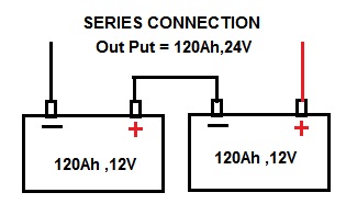
  • Series configurations will add the voltage of the two batteries but keep the amperage rating (Amp Hours) same. * Condition-I : * Selection of Battery for Voltage = Volt of Each Battery <= Volt of Battery Bank * Selection of Battery for Voltage =12< 24 * Condition-I is O.K * No of Battery for Voltage = Volt of Battery Bank / Volt of Each Battery * No of Battery for Voltage =24/12 = 2 No’s * Condition-II : * Selection of Battery for Amp Hr = Amp Hr of Battery Bank <= Amp Hr of Each Battery * Selection of Battery for Amp Hr =3<=120 * Condition-II is O.K * We can use Series Connection for Battery & No of Battery required 2 No’s

series_battery_config Configuration

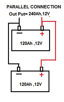
  • In Parallel connection, the current rating will increase but the voltage will be the same. * More the number of batteries more will be the amp/hour. Two batteries will produce twice the amp/hour of a single battery. * Condition-I : * Selection of Battery for Amp Hr = Amp Hr of Battery Bank / Amp Hr of Each Battery <=1 * Selection of Battery for Amp Hr =101/120 = 0.84=1 No’s * Condition-I is O.K * Condition-II : * Selection of Battery for Voltage = Volt of Battery Bank = Volt of Each Battery * Condition-II :Selection of Battery for Voltage for Amp Hr = 24<=12 * Condition-II is Not Full Fill * We cannot use Parallel Connection for Battery as per our requirement But If We do Practically It is Possible and it will give more Hours of back

parallel_battery_config Connection:

  • Connecting the batteries up in series will increase both the voltage and the run time. * Condition-I : * Selection of Battery for Amp Hr = Amp Hr of Each Battery <= Amp Hr of Battery Bank * Selection of Battery for Amp Hr =120<=101 * Condition-I is Not Full Fill * Condition-II : * Selection of Battery for Voltage = Volt of Each Battery <= Volt of Battery Bank * Selection of Battery for Voltage = 12<=24 * Condition-II is OK * We cannot use Parallel Connection for Battery

If We Select 60 Amp Hr , 12V DC Battery for Battery Bank:

Series Connection:

  • Selection of Battery for Voltage = Volt of Each Battery <= Volt of Battery Bank * Selection of Battery for Voltage =12< 24 * Condition-I is O.K * No of Battery for Voltage = Volt of Battery Bank / Volt of Each Battery * No of Battery for Voltage =24/12 = 2 No’s * Condition-II : * Selection of Battery for Amp Hr = Amp Hr of Battery Bank <= Amp Hr of Each Battery * Selection of Battery for Amp Hr =3<=60 * Condition-II is Not Full Fill * We can use Series Connection for Battery

Parallel Configuration

  • Condition-I : * Selection of Battery for Amp Hr = Amp Hr of Battery Bank / Amp Hr of Each Battery <=1 * Selection of Battery for Amp Hr =101/60 = 1.63=1 No’s * Condition-I is O.K * Condition-II : * Selection of Battery for Voltage = Volt of Battery Bank = Volt of Each Battery * Condition-II :Selection of Battery for Voltage for Amp Hr …

5. Calculate Required Air ventilation and Heat generation of D.G Set

CALCULATE REQUIRED AIR VENTILATION AND HEAT GENERATION OF D.G SET

HEAT GENERATED BY GENERATOR:

  • For generator set installations, the heat radiated by the generator can be estimated by * H (kW) =P X ((1/Eff)-1) * H (Btu/min) =P X ((1/EFF)-1) x56.9 * Where: * H = Heat Radiated by the Generator (kW), (Btu/min) * P = Generator Output at Maximum Engine Rating (kW) * Eff = Generator Efficiency % / 100% * Example: 975 kW standby generator set has a generator efficiency of 92%. The generator radiant heat for this genset can be calculated as follows. * P = 975 kW * Efficiency = 92% = 0.92 * H = 975 x ((1/92%) – 1) * H= 84.78 kW * H = 975 x ((1/92%) – 1) x 56.9 * H = 4824 Btu/min

 TYPES OF VENTILATION SYSTEM:

  • Type:1 (Preferred Design) (Routing Factor of 1) * Outside air is brought into the engine room through a system of ducts. These ducts should be routed between engines, at floor level, and discharge air near the bottom of the engine and generator. . * Ventilation air exhaust fans should be mounted or ducted at the highest point in the engine room. They should be directly over heat sources. This system provides the best ventilation with the least amount of air required. * Type 2 (Skid Design) (Routing Factor of 1) * Outside air into the engine room through a system of ducts and routes it between engines. * Type 2, however, directs airflow under the engine and generator so the air is discharged upward at the engines * The most economical method to achieve this design is to use a service platform. The platform is built up around the engines and serves as the top of the duct * Ventilation air exhaust fans should be mounted or ducted at the highest point in the engine room. They should be directly over heat sources. * This system provides the best ventilation with the least amount of air required. * Type 3 (Alternate Design) (Routing Factor of 1.5) * If Ventilation Type 1or Type 2 is not feasible, an alternative is Type 3; however, this routing configuration will require approximately 50% more airflow than Type 1. * Outside air is brought into the engine room utilizing fans or large intake ducts. The inlet is placed as far away as practical from heat sources and discharged into the engine room as low as possible. The air them flows across the engine room * Ventilation air exhaust fans should be mounted or ducted at the highest point in the engine room. Preferably, they should be directly over heat sources * Type 4 (Less Effective Design) (Routing Factor of 2.5) * If Ventilation Type 1, Type 2 and Type 3 are not feasible, then Type-4 method can be used; however, it provides the least efficient ventilation and requires approximately two and a half times the airflow of Ventilation Type 1 * Outside air is brought into the engine room using supply fans, and discharged toward the turbocharger air inlets on the engines. * Ventilation exhaust fans should be mounted or duct from the corners of the engine room * This system mixes the hottest air in the engine room with the incoming cool air, raising the temperature of all air in the engine room. * It also interferes with the natural convection flow of hot air rising to exhaust fans. * Engine rooms can be ventilated this way, but it requires extra large capacity ventilating fans.

VENTILATION FOR GENERATOR:

  • When Generator set installations in Room proper ventilation is required for Generator set. * A properly designed engine room ventilation system will maintain engine room air temperatures within 8.5 to 12.5°C (15 to 22.5°F) above the ambient air temperature. * For example, If the engine room temperature is 24°C (75°F) without the engine running, the ventilation system should maintain the room temperature between 32.5°C (90°F) and 36.5°C (97.5°F) while the engine is in operation. * Ensures engine room temperature does not exceed 49°C (120°F). * Required Ventilating Air is calculated as * V=((H / D x Cp x T)+ Combustion Air) X F * Where: * V = Ventilating Air (m3/min), (cfm) * H = Heat Radiation i.e. engine, generator, aux (kW),(Btu/min) * D = Density of Air at air temperature 38°C (100°F). The density is 1.099 kg/m3 (0.071 lb/ft3) * CP = Specific Heat of Air (0.017 kW x min/kg x °C),(0.24 Btu/LBS/°F) * T = Permissible temperature rise in engine room (°C), (°F) * F = Routing factor based on the ventilation type * Example: The engine room for generator set has a Type 1 ventilation routing configuration and a dedicated duct for combustion air. It has a heat rejection value of 659 kW (37,478 Btu/min) and a permissible rise in engine room temperature of 11°C (20°F). * V=((659 / 1.0099X0.017X11)+ 0)X1 * V = 3206.61 m3/min * V=((659 / 0.071 X 0.024 X 20)+ 0)X1 * V = 109970.7 cfm

6. Calculate Size of Ventilation Fan

CALCULATE SIZE OF VENTILATION FAN

  • Calculate Size of Ventilation Fan for Bathroom of 10 Foot Long,15 Foot width and 10 foot height .

CALCULATION:

  • Area of the Room=Length x Width x Height * Area of the Room=10 x 15 x 10 =1500 Cub. Foot * From the table Air Changing Rate (ACH) for Bathroom = 8 Times/Hour. * Size of Ventilation Fan = (Area of Room x ACH ) / 60 * Size of Ventilation Fan = (1500 x 8 ) / 60 = 200 CFM

  • SIZE OF VENTILATION FAN = 200 CFM

Recommended Air Change Rates For Room (ACH) Type of Room Air Change Rate /Hour Consider Shower Area 15 To 20 20 Bathroom & Shower Rooms 15 To 20 15 Bathroom 6 To 10 8 Bedrooms 2 To 4 4 Halls & Landings 4 To 6 5 Kitchens 10 To 20 15 Living & Other Domestic Rooms 4 To 6 5 Toilets – Domestic 6 To 10 8 Utility Rooms 15 To 20 15 Cafés 10 To 15 15 Canteens 8 To 12 10 Cellars 3 To 10 6 Changing Rooms with Showers 15 To 20 15 Conference Rooms 8 To 12 8 Garages 6 To 10 8 Hairdressing Salons 10 To 15 13 Hospital Wards 6 To 8 7 Laundries & Launderettes 10 To 15 13 Meeting Rooms 6 To 12 7 Offices 4 To 6 6 Restaurants & Bars 10 To 15 12 School Rooms 5 To 7 6 Shops 8 To 10 9 Sports Facilities 4 To 6 6 Store Rooms 3 To 6 5 Workshops 6 To 10 8 Assembly rooms 4 To 8 8 Bakeries 20 To 30 25 Banks/Building Societies 4 To 8 5 Billiard Rooms * 6 To 8 5 Boiler Rooms 15 To 30 25 Canteens 8 To 12 10 Changing Rooms Main area 6 To 10 8 Changing Rooms Shower area 15 To 20 17 Churches 1 To 3 3 Cinemas and theatres * 10 To 15 12 Club rooms 0.12 0.12 Compressor rooms 10 To 15 15 Conference rooms 8 To 12 12 Dairies 8 To 10 10 Dance halls 0.12 0.12 Dental surgeries 12 To 15 15 Dye works 20 – 30 30 Electroplating shops 10 To 12 Engine rooms 15 To 30 30 Entrance halls & corridors 3 To 5 5 Factories and workshops 8 To 10 10 Foundries 15 To 30 20 Glasshouses 25 To 60 50 Gymnasiums 0.6 0.6 Hospitals – Sterilizing 15 To 25 20 Kitchens – Domestic 15 To 20 15 Kitchens – Commercial 0.3 0.3 Laboratories 6 To 15 12 Lavatories 6 To 15 12 Lecture theatres 5 To 8 8 Libraries 3 To 5 4 Mushroom houses 6 To 10 8 Paint shops (not cellulose) 10 To 20 15 Photo & X-ray darkrooms 10 To 15 12 Public house bars 0.12 0.12 Recording control rooms 15 To 25 20 Recording studios 10 To 12 10 Shops and supermarkets 8 To 15 12 Squash courts 0.04 0.04 Swimming baths 10 To 15 12 Welding shops 15 To 30 20

Cover image
(7) OTHERS:

7. Calculate Size of Pole Foundation & Wind Pressure on Pole

CALCULATE SIZE OF POLE FOUNDATION & WIND PRESSURE ON POLE

EXAMPLE:

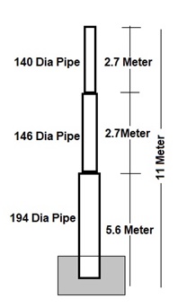
  • Calculate Pole foundation size and Wind pressure on Pole for following Details. * Tubular Street Light Pole (430V) height is 11 Meter which is in made with three different size of Tubular Pipe. * First Part is 2.7 meter height with 140mm diameter, * Second part of Pole is 2.7 meter height with 146 mm diameter and * Third part of Pole is 5.6 meter height with 194 mm diameter. * Weight of Pole is 241 kg and there is no any other Flood Light Fixtures Load on Pole. * Total Safety Factor is 2. * Wind zone category is 3. * The Pole is installed in open terrain with well scattered obstructions having height generally between 1.5 m to 10 m. * Foundation of pole is 700mm length, 700mm width and 1.95 meter depth. The Average weight of foundation concrete is 2500 Kg/M3.

1

CALCULATION:

 WIND PRESSURE ACCORDING TO LOCATION:

  • Wind Zone is 3 so Wind Speed as per following Table.

Basic Wind Speed-Vb (As per IS 802-Part1) Wind Zone Basic Wind Speed, vb m/s 1 33 2 39 3 44 4 47 5 50 6 55

  • Wind Speed (vb) = 44Mile/Second. * Co-efficient Factor (K0)=1.37 * K0 is a factor to convert 3 seconds peak gust speed into average speed of wind during 10 minutes period at a level of 10 meters above ground. K0 may be taken as 1.375. * The Pole is used for 430Vand wind zone is 3 so Risk Co-efficient (K1) as per following Table

Table 2 Risk Coefficient K1 for Different Reliability Levels and Wind Zones (As per IS 802-Part1) Reliability Level Wind Zone-1 Wind Zone-2 Wind Zone-3 Wind Zone-4 Wind Zone-5 Wind Zone-6 1 (Up to 400KV) 1 1 1 1 1 1 2 (Above 400KV) 1.08 1.1 1.11 1.12 1.13 1.14 3 (River Crossing) 1.17 1.22 1.25 1.27 1.28 1.3

  • Risk Co-efficient (K1) =1 * Terrain category (K2) for Open terrain with well scattered obstructions having height generally between 1.5 m to 10 m is 1 as per following Table * Terrain category (K2)=1

Terrain Roughness Coefficient, K2 (As per IS 802-Part1) Terrain Category Category 1 Category 2 Category 3 Exposed open terrain with no obstruction and in which the average height of any object surrounding the structure is less than 1.5 m. Open terrain with well scattered obstructions having height generally between 1.5 m to 10 m. Terrain with numerous closely spaced obstructions. Coefficient, K2 1.08 1 0.85

  • Reference Wind Speed (Vr)= Vb / K0. * Reference Wind Speed (Vr)= 44 / 1.37 =32 Mile/Second. * Design wind Speed (vd)= Vr X K1 X K2. * Design wind Speed (vd)= 32 X 1 X 1 =32 Mile/Second. * Design Wind Pressure (Pd)=0.6 x vd2 * Design Wind Pressure (Pd)=0.6 x (32)2 =614.4 N/m2 * Design Wind Pressure (Pd)=614.4/10 =61.4 Kg/m2

FOUNDATION DETAIL:

  • Total Weight =Pole Weight +Foundation Weight. * Total Weight = 241 +(0.7×0.7×1.95×2500) =2620.75 Kg * Stabilizing Moment = Total Weight X (Foundation Length/2) * Stabilizing Moment = 2620.75 X (0.7/2) = 920.41 Kg/Meter.

POLE DETAIL:

  • First Part of Pole (h1) = 2.7 meter * Diameter of First Part (d1) =140mm * Second Part of Pole (h2) = 2.7 meter * Diameter of Second Part (d2) =146mm * Third Part of Pole (h3) = 5.6 meter * Diameter of Third Part (d3) =194mm .

WIND PRESSURE ON POLE:

  • Overturning Moment due to the wind on 1st Part of the pole=pdxh1xd1x(h1/2+h2+h3)x0.6 * Overturning Moment due to the wind on 1st Part of the pole=61.4×2.7x(140/1000)x(2.7/2+2.7+5.61)x0.6 * Overturning Moment due to the wind on 1st Part of the pole=134.47 Kg/meter—I * Overturning Moment due to the wind on 2nd Part of the pole=pdxh2xd2x(h2/2+h3)x0.6 * Overturning Moment due to the wind on 2nd Part of the pole=61.4×2.7x(146/1000)x(2.7/2+5.61)x0.6 * Overturning Moment due to the wind on 2nd Part of the pole=112.76 Kg/meter.—-II * Overturning Moment due to the wind on 3rd Part of the pole=pdxh3xd3x(h3/2)x0.6 * Overturning Moment due to the wind on 3rd Part of the pole=61.4×5.6x(194/1000)x(5.6/2)x0.6 * Overturning Moment due to the wind on 3rd Part of the pole=112.14 Kg/meter.—III * Total Overturning Moment on Pole due to Wind=134.47+112.76+112.14=359.36 Kg/meter.

 SAFETY FACTOR:

  • Calculated Safety Factor= Stabilizing Moment / Total Overturning Moment on Pole. * Calculated Safety Factor=920.41/ 359.36 =2.56. * For safe Design Calculated Safety Factor > Safety Factor * Here Calculated Safety Factor (2.56) > Safety Factor (2) hence * Design is OK * B : If Calculated Safety Factor < Safety Factor then Change Foundation Size (Length, width or depth)

8. Calculate Size of Anchor Fastener for Water Pipe Support

CALCULATE SIZE OF ANCHOR FASTENER FOR CABLE TRAY SUPPORT.

April 28, 2024 1 Comment

Calculate Size of Anchor fastener for Cable Tray Support having following Details

  • CABLE TRAY DETAIL: * Size of Cable Tray=600mm Ladder Type Cable Tray * Weight of Cable Tray=120 kg/meter * CABLE DETAILS (LAID IN CABLE TRAY) * Size of Cable =3.5Cx300 Sq.mm, Alu, XLPE, Armored Cable * No of Cable / Cable tray= 6 No’s * Weight of Cable = 5.9 Kg/meter * Size of Cable =3.5Cx150 Sq.mm, Alu, XLPE, Armored Cable * No of Cable / Cable tray= 2 No’s * Weight of Cable = 4.5 Kg/meter. * CABLE TRAY SUPPORT DETAILS * Cable Tray Support installed at 1 Meter of Cable Tray * Weight of Cable Tray Support =5.8 Kg/meter * Safety Factor=5

CALCULATIONS

  • Weight of Cable Tray Support = No of Support X Weight of Support * Weight of Cable Tray Support =1×5.8 Kg/Meter * Weight of Cable Tray Support =5.8 Kg/Meter———(A) * Weight of Cable Tray = No of Cable Tray X Weight of Tray * Weight of Cable Tray =1×120 * Weight of Cable Tray =120 Kg/Meter———(B) * Weight of 3.5Cx300 Sq.mm Cable = No of Cable X Weight of Cable * Weight of 3.5Cx300 Sq.mm Cable =6×5.9 * Weight of 3.5Cx300 Sq.mm Cable =35.4 Kg/Meter———(C1) * Weight of 3.5Cx150 Sq.mm Cable = No of Cable X Weight of Cable * Weight of 3.5Cx150 Sq.mm Cable =2×4.5 * Weight of 3.5Cx150 Sq.mm Cable =9 Kg/Meter———(C2) * Total Weight =Safety Factor X (Weight of Cable Tray support + Weight of Cable Tray + Weight of Cables) * Total Weight =5X (5.8+120+35.4+9) Kg/Meter * Total Weight=851 Kg/Meter—————–(1) * Consider 4 No of 10mm size of Anchor Fastener having Basic Tensile Load Capacity of 5KN at each Support. * Total Tensile Load= No of Anchor Fastener X 101.97XAnchor Tensile Load Capacity (KN) * Total Tensile Load=4×101.97×5 * Total Tensile Load=1876 Kg/Meter————(2)

Here Total Tensile Load Capacity of Anchor Fastener (1876 Kg/Meter) > Total Weight (851 Kg/Meter) hence Size of Anchor Fastener is OK