Site logo
Electrical Engineering Academy
Cover image
(4) EARTHING / LIGHTING PROTECTION:

1. Calculate Numbers of Plate/Pipe/Strip Earthing’s (Part-3)

CALCULATE NUMBERS OF PLATE/PIPE/STRIP EARTHINGS (PART-3)

CALCULATE MIN. CROSS SECTION AREA OF EARTHING CONDUCTOR:

  • Cross Section Area of Earthing Conductor As per IS 3043

  • CROSS SECTION AREA OF EARTHING CONDUCTOR (A) =(IF X√T) / K

  • Where t= Fault current Time (Second). * K= Material Constant. * Example: * Calculate Cross Section Area of GI Earthing Conductor for System has 50KA Fault Current for 1 second. Corrosion will be 1.0 % Per Year and No of Year for Replacement is 20 Years. * Cross Section Area of Earthing Conductor (A) =(If x√t) / K * Here If=50000 Amp * T= 1Second * K=80 (Material Constant, For GI=80, copper K=205, Aluminium K=126). * Cross Section Area of Earthing Conductor (A) =(50000×1)/80 * Cross Section Area of GI Earthing Conductor (A)=625 Sq.mm * Allowance for Corrosion = 1.0 % Per Year & Number of Year before replacement say = 20 Years * Total allowance = 20 x 1.0% = 20% * Safety factor = 1.5 * Required Earthing Conductor size = Cross sectional area x Total allowance x Safety factor * Required Earthing Conductor size = 1125 Sq.mm say 1200 Sq.mm * Hence, Considered 1Nox12x100 mm GI Strip or 2Nox6 x 100 mm GI Strips

 THUMB RULE FOR CALCULATE NUMBER OF EARTHING ROD:

  • The approximate earth resistance of the Rod/Pipe electrodes can be calculated by

  • EARTH RESISTANCE OF THE ROD/PIPE ELECTRODES R= K X Ρ/L

  • Where ρ = Resistivity of earth in Ohm-Meter * L= Length of the electrode in Meter. * d= Diameter of the electrode in Meter. * K=0.75 if 25< L/d < 100. * K=1 if 100 < L/d < 600 * K=1.2 o/L if 600 < L/d < 300

  • NUMBER OF ELECTRODE IF FIND OUT BY EQUATION OF R(D) =(1.5/N) X R

  • Where R(d) = Desired earth resistance * R= Resistance of single electrode * N= No. of electrodes installed in parallel at a distance of 3 to 4 Meter interval. * Example: * Calculate Earthing Pipe Resistance and Number of Electrode for getting Earthing Resistance of 1 Ω ,Soil Resistivity of ρ=40, Length=2.5 Meter, Diameter of Pipe= 38 mm. * Here L/d = 2.5/0.038=65.78 so K=0.75 * The Earth Resistance of the Pipe electrodes R= K x ρ/L =0.75×65.78=12 Ω * One electrode the earth resistance is 12 Ω. * To get Earth resistance of 1 Ω the total Number of electrodes required =(1.5×12)/1 =18 No

 CALCULATING RESISTANCE & NUMBER OF EARTHING ROD:

  • Reference: As per EHV Transmission Line Reference Book page: 290 and Electrical Transmission & Distribution Reference Book Westinghouse Electric Corporation, Section-I Page: 570-590.

  • EARTHING RESISTANCE OF SINGLE RODS: R = ΡX[LN (2L/A)-1]/(2×3.14XL)

  • EARTHING RESISTANCE OF PARALLEL RODS: R = ΡX[LN (2L/A]/ (2×3.14XL)

  • Where L= length of rod in ground Meter, * a= radius of rod Meter * ρ = ground resistivity, ohm- Meter * A= √(axS) * S= Rod separation Meter

Untitled

 FACTOR AFFECTS ON GROUND RESISTANCE:

  • The NEC code requires a minimum ground electrode length of 2.5 meters (8.0 feet) to be in contact with the soil. But, there are some factor that affect the ground resistance of a ground system: * Length / Depth of the ground electrode: double the length, reduce ground resistance by up to 40%. * Diameter of the ground electrode: double the diameter, lower ground resistance by only 10%. * Number of ground electrodes: for increased effectiveness, space additional electrodes at least equal to the depth of the ground electrodes. * Ground system design: single ground rod to ground plate.

 THE GI EARTHING CONDUCTOR SIZES FOR VARIOUS EQUIPMENTS:

No Equipments Earth Strip Size

1

HT switchgear, structures, cable trays & fence, rails, gate and steel column

55 X 6 mm (GI)

2

Lighting Arrestor

25 X 3 mm (Copper)

3

PLC Panel

25 X 3 mm (Copper)

4

DG & Transformer Neutral

50X6 mm (Copper)

5

Transformer Body

50X6 mm (GI)

6

Control & Relay Panel

25 X 6 mm (GI)

7

Lighting Panel & Local Panel

25 X 6 mm (GI)

8

Distribution Board

25 X 6 mm (GI)

9

Motor up to 5.5 kw

4 mm2 (GI)

10

Motor 5.5 kw to 55 kw

25 X 6 mm (GI)

11

Motor 22 kw to 55 kw

40 X 6 mm (GI)

12

Motor Above 55 kw

55 X 6 mm (GI)

 Selection of Earthing System:

Installations/ Isc Capacity

IR Value Required

Soil Type/ Resistivity

Earth System

House hold earthing/3kA 8 ohm Normal Soil/ up to 50 ohm-meter Single Electrode Sandy Soil/ between 50 to 2000 ohm- meter Single Electrode Rocky Soil/ More than 2000 ohm- meter Multiple Electrodes Commercial premises,Office / 5kA 2 ohm Normal Soil/ up to 50 ohm-meter Single Electrode Sandy Soil/ between 50 to 2000 ohm- meter Multiple Electrodes Rocky Soil/ More than 2000 ohm- meter Multiple Electrodes Transformers, substationearthing, LT line equipment/ 15kA less than 1 ohm Normal Soil/ up to 50 ohm-meter Single Electrode Sandy Soil/ between 50 to 2000 ohm- meter Multiple Electrodes Rocky Soil/ More than 2000 ohm- meter Multiple Electrodes LA, High current Equipmen…

2. Calculate Numbers of Plate/Pipe/Strip Earthing’s (Part-2)

CALCULATE NUMBERS OF PLATE/PIPE/STRIP EARTHINGS (PART-2)

(2)CALCULATE NUMBER OF PLATE EARTHING:

  • The Earth Resistance of Single Plate electrode is calculated as per IS 3040:

  • R=Ρ/A√(3.14/A)

  • Where ρ=Resistivity of Soil (Ω Meter), * A=Area of both side of Plate (m2), * Example: Calculate Number of CI Earthing Plate of 600×600 mm, System has Fault current 65KA for 1 Sec and Soil Resistivity is 100 Ω-Meters. * Current Density At The Surface of Earth Electrode (As per IS 3043): * Max. Allowable Current Density I = 7.57×1000/(√ρxt) A/m2 * Max. Allowable Current Density = 7.57×1000/(√100X1)=757 A/m2 * Surface area of both side of single 600×600 mm Plate= 2 x lxw=2 x 0.06×0.06 = 0.72 m2 * Max. current dissipated by one Earthing Plate = Current Density x Surface area of electrode * Max. current dissipated by one Earthing Plate =757×0.72= 545.04 Amps * Resistance of Earthing Plate (Isolated)(R)=ρ/A√(3.14/A) * Resistance of Earthing Plate (Isolated)(R)=100/0.72x√(3.14/.072)=290.14 Ω * Number of Earthing Plate required =Fault Current / Max.current dissipated by one Earthing Pipe. * Number of Earthing Plate required= 65000/545.04 =119 No’s. * Total Number of Earthing Plate required = 119 No’s. * Overall resistance of 119 No of Earthing Plate=290.14/119=2.438 Ω.

(3)CALCULATING RESISTANCE OF BARED EARTHING STRIP:

1)CALCULATION FOR EARTH RESISTANCE OF BURIED STRIP (AS PER IEEE):

  • The Earth Resistance of Single Strip of Rod buried in ground is

  • R=Ρ/PX3.14XL (LOGE (2XLXL/WXH)+Q)

  • Where ρ=Resistivity of Soil (Ω Meter), * h=Depth of Electrode (Meter), * w=Width of Strip or Diameter of Conductor (Meter) * L=Length of Strip or Conductor (Meter) * P and Q are Coefficients

2)CALCULATION FOR EARTH RESISTANCE OF BURIED STRIP(AS PER IS 3043):

  • The Earth Resistance of Single Strip of Rod buried in ground is

  • R=100XΡ/2×3.14XL (LOGE (2XLXL/WXT))

  • Where ρ=Resistivity of Soil (Ω Meter), * L=Length of Strip or Conductor (cm) * w=Width of Strip or Diameter of Conductor (cm) * t= Depth of burial (cm) * Example : * Calculate Earthing Resistance of Earthing strip/wire of 36mm Diameter, 262 meter long buried at 500mm depth in ground, soil Resistivity is 65 Ω Meter. * Here R = Resistance of earth rod in W. * r = Resistivity of soil(Ω Meter) = 65 Ω Meter * l = length of the rod (cm) = 262m = 26200 cm * d = internal diameter of rod(cm) = 36mm = 3.6cm * h = Depth of the buried strip/rod (cm)= 500mm = 50cm * Resistance of Earthing Strip/Conductor (R)=ρ/2×3.14xL (loge (2xLxL/Wt)) * Resistance of Earthing Strip/Conductor (R)=65/2×3.14x26200xln(2x26200x26200/3.6×50) * Resistance of Earthing Strip/Conductor (R)== 1.7 Ω

3. Calculate Numbers of Plate/Pipe/Strip Earthing’s (Part-1)

CALCULATE NUMBERS OF PLATE/PIPE/STRIP EARTHINGS (PART-1)

INTRODUCTION:

  • Number of Earthing Electrode and Earthing Resistance depends on the resistivity of soil and time for fault Current to pass through (1 sec or 3 sec). If we divide the area for earthing required by the area of one earth plate gives the no of Earth pits required. * There is no general rule to calculate the exact no of earth Pits and Size of Earthing Strip, But discharging of leakage current is certainly dependent on the cross section area of the material so for any equipment the earth strip size is calculated on the current to be carried by that strip. First the leakage current to be carried is calculated and then size of the strip is determined. * For most of the Electrical equipments like Transformer, DG set etc., the General concept is to have 4 no earth pits.2 no’s for body earthing With 2 separate strips with the pits shorted and 2 nos for Neutral with 2 separate strips with the pits shorted. * The Size of Neutral Earthing Strip should be Capable to carry neutral current of that equipment. * The Size of Body Earthing should be capable to carry half of neutral Current. * For example for 100kVA transformer, the full load Current is around 140A.The strip connected should be Capable to carry at least 70A (neutral current) which means a Strip of GI 25x3mm should be enough to carry the current And for body a strip of 25×3 will do the needful. * Normally we consider the strip size that is generally used as Standards. However a strip with lesser size which can carry a current of 35A can be used for body earthing. The reason for using 2 earth pits for each body and neutral and then shorting them is to serve as back up. If one strip gets Corroded and cuts the continuity is broken and the other Leakage current flows through the other run thery by completing the circuit. Similarly for panels the no of pits should be 2 nos. The size can be decided on the main incomer Breaker. * For example if main incomer to breaker is 400A, then Body earthing for panel can have a strip size of 25×6 mm Which can easily carry 100A. * Number of earth pits is decided by considering the total Fault current to be dissipated to the ground in case of Fault and the current that can be dissipated by each earth Pit. * Normally the density of current for GI strip can be roughly 200 amps per square cam. Based on the length and dia of the Pipe used the Number of Earthing Pits can be finalized.

 (1) CALCULATE NUMBERS OF PIPE EARTHING:

 (A) EARTHING RESISTANCE & NO OF ROD FOR ISOLATED EARTH PIT (WITHOUT BURIED EARTHING STRIP):

  • The Earth Resistance of Single Rod or Pipe electrode is calculated as per BS 7430:

  • R=Ρ/2×3.14XL (LOGE (8XL/D)-1)

  • Where ρ=Resistivity of Soil (Ω Meter), * L=Length of Electrode (Meter), * D=Diameter of Electrode (Meter) * Example: * Calculate Isolated Earthing Rod Resistance. The Earthing Rod is 4 Meter Long and having 12.2mm Diameter, Soil Resistivity 500 Ω Meter. * R=500/ (2×3.14×4) x (Loge (8×4/0.0125)-1) =156.19 Ω. * The Earth Resistance of Single Rod or Pipe electrode is calculated as per IS 3040:

  • R=100XΡ/2×3.14XL (LOGE(4XL/D))

  • Where ρ=Resistivity of Soil (Ω Meter), * L=Length of Electrode (cm), * D=Diameter of Electrode (cm) * Example: * Calculate Number of CI Earthing Pipe of 100mm diameter, 3 Meter length. System has Fault current 50KA for 1 Sec and Soil Resistivity is 72.44 Ω-Meters. * Current Density At The Surface of Earth Electrode (As per IS 3043): * Max. Allowable Current Density I = 7.57×1000/(√ρxt) A/m2 * Max. Allowable Current Density = 7.57×1000/(√72.44X1)=889.419 A/m2 * Surface area of one 100mm dia. 3 meter Pipe= 2 x 3.14 x r x L=2 x 3.14 x 0.05 x3 = 0.942 m2 * Max. current dissipated by one Earthing Pipe = Current Density x Surface area of electrode * Max. current dissipated by one Earthing Pipe = 889.419x 0.942 = 837.83 A say 838 Amps * Number of Earthing Pipe required =Fault Current / Max.current dissipated by one Earthing Pipe. * Number of Earthing Pipe required= 50000/838 =59.66 Say 60 No’s. * Total Number of Earthing Pipe required = 60 No’s. * Resistance of Earthing Pipe (Isolated) R=100xρ/2×3.14xLx(loge (4XL/d)) * Resistance of Earthing Pipe (Isolated) R=100×72.44/2×3.14x300x(loge (4X300/10))=7.99 Ω/Pipe * Overall resistance of 60 No of Earthing Pipe=7.99/60=0.133 Ω.

(B) EARTHING RESISTANCE & NO OF ROD FOR ISOLATED EARTH PIT (WITH BURIED EARTHING STRIP):

  • Resistance of Earth Strip(R) As per IS 3043

  • R=Ρ/2×3.14XLX (LOGE (2XLXL/WT)).

  • Example: * Calculate GI Strip having width of 12mm , length of 2200 Meter buried in ground at depth of 200mm,Soil Resistivity is 72.44 Ω-Meter * Resistance of Earth Strip(Re)=72.44/2×3.14x2200x(loge (2x2200x2200/.2x.012))= 0.050 Ω * From above Calculation Overall resistance of 60 No of Earthing Pipe (Rp) = 0.133 Ω. And it connected to bury Earthing Strip. Here Net Ea…

4. Calculate Lightening Protection for Building / Structure

CALCULATE LIGHTNING PROTECTION FOR BUILDING / STRUCTURE

Example: Calculate Whether Lightning Protection is required or not for following Building. Calculate No of Down Conductor for Lightning Protection

Area of Building / Structure:

  • Length of Building (L) = 60 Meter. * Width of Building ( W ) = 28 Meter. * Height of Building (H) = 23 Meter.

Lightning Stock Flushing Density

  • Number of Thunderstorm (N)= 80.00 Days/Year * Lightning Flash Density (Ng)=69 km2/Year * Application of Structure (A)= Houses & Buildings * Type of Constructions (B)= Steel framed encased without Metal Roof * Contests or Consequential Effects (C)= Domestic / Office Buildings * Degree of Isolation (D)= Structure in a large area having greater height * Type of Country (E)= Flat country at any level * Maximum Acceptable Overall Risk Factor =0.00000001

Reference Table As per IS:2309 Thunder Storm Days / Year Lightning Flash Density (Flashes to Ground /km2/year) 5 0.2 10 0.5 20 1.1 30 1.9 40 2.8 50 3.7 60 4.7 80 6.9 100 9.2

Application of Structure Factor Houses & Buildings 0.3 Houses & Buildings with outside aerial 0.7 Factories / workshop/ Laboratories 1 Office blocks / Hotel 1.2 Block of Flats / Residences Building 1.2 Churches/ Hall / Theaters / Museums, Exhibitions 1.3 Departmental stores / Post Offices 1.3 Stations / Airports / Stadium 1.3 Schools / Hospitals / Children’s Home 1.7 Others 1.2

Type of Constructions Factor Steel framed encased without Metal Roof 0.2 Reinforced concrete without Metal Roof 0.4 Steel framed encased with Metal Roof 0.8 Reinforced concrete with Metal Roof 1 Brick / Plain concrete or masonry without Metal Roof 1.4 Timber framed or clad without Metal Roof 1.7 Brick / Plain concrete or masonry with Metal Roof 2 Timber framed or clad with Metal Roof

Contests or Consequential Effects Factor Domestic / Office Buildings 0.3 Factories / Workshop 0.3 Industrial & Agricultural Buildings 0.8 Power stations / Gas works 1 Telephone exchange / Radio Station 1 Industrial key plants, Ancient monuments 1.3 Historic Buildings / Museums / Art Galleries 1.3 Schools / hospitals / Children Homes 1.7

Degree of Isolation Factor Structure in a large area having greater height 0.4 Structure located in a area of the same height 1 Structure completely Isolated 2

CALCULATION:

Collection Area (Ac)=(L x W) + 2 (L x H) + 2(W x H) +(3.14 x H2)

  • Collection Area (Ac) = (60×28)+2x(60×23)+2x(28×23)+(3.14x23x23) * Collection Area (Ac) =7389 Meter2

Probable No of Strikes to Building / Structure (P)= Ac x Ng x 10-6 No’s / Year

  • Probable No of Strikes to Building / Structure (P)= 7389x69x10–6 No’s / Year * Probable No of Strikes to Building / Structure (P)= 05098 No’s / Year

Overall Multiplying Factor (M) =A x B x C x D x E

  • Application of Structure (A)= Houses & Buildings as per Table Multiplying Factor = 0.3 * Type of Constructions (B)= Steel framed encased without Metal Roof as per Table Multiplying Factor =0.2 * Contests or Consequential Effects (C)= Domestic / Office Buildings as per Table Multiplying Factor =0.3 * Degree of Isolation (D)= Structure in a large area having greater height as per Table Multiplying Factor =0.4 * Type of Country (E)= Flat country at any level so as per Table Multiplying Factor =0.3 * Overall Multiplying Factor (M) =0.3×0.2×0.3×0.4×0.3 * Overall Multiplying Factor (M) =0.00216

Overall Risk Factor Calculated (xc)= M x P

  • Overall Risk Factor Calculated (xc)= 0.00216 x0.05098 * Overall Risk Factor Calculated (xc)= 000110127

 Base Area of Structure (Ab) = (LxW)

  • Base Area of Structure (Ab)=60×28 * Base Area of Structure (Ab)=1680 Meter2

Perimeter of Structure (P) =2x (L+W)

  • Perimeter of Structure (P)=2x(60+28) * Perimeter of Structure (P)=176 Meter

Lightning Protection Required or Not

  • If Calculated Overall Risk Factor Calculated > Maximum Acceptable Overall Risk Factor than only Lighting Protection Required * Here Calculated Overall Risk Factor is 0.000110127 > Max Acceptable Overall Risk Factor is 00000001 * Lightning Protection is Required

 No of Down Conductor

  • Down Conductors As per Base Area of Structure (s) =1+(Ab-100)/300 * Down Conductors As per Base Area of Structure (s) =1+(1680-100)/300 * Down Conductors As per Base Area of Structure (s) =6 No’s * Down Conductors As per Perimeter of Structure (t)= P/30 * Down Conductors As per Perimeter of Structure (t)= 176/30 * Down Conductors As per Perimeter of Structure (t)= 6 No’s * Minimum No of Down Conductor is 6 No’s

 RESULTS:

  • Lightning Protection is Required * Down Conductors As per Base Area of Structure (s) =6 No’s * Down Conductors As per Perimeter of Structure (t)= 6 No’s * Minimum No of Down Conductor is 6 No’s

5. Calculate Size of Neutral Earthing Transformer (NET)

CALCULATE SIZE OF NEUTRAL EARTHING TRANSFORMER (NET)

Calculate Size of Neutral Earthing Transformer (NET) having following details

 Main Transformer Detail :

  • Primary Voltage(PVL): 33KV * Secondary Voltage (SVL): 11 KV * Frequency(f)=50Hz * Transformer Capacitance / Phase(c1)=0.006 µ Farad * Transformer Cable Capacitance / Phase(c2)= 0003 µ Farad * Surge Arrestor Capacitance / Phase(c3)=0.25 µ Farad * Other Capacitance / Phase(c4)=0 µ Farad

Required for Neutral Earthing Transformer:

  • Primary Voltage of the Grounding Transformer (Vp) =11KV * Secondary Voltage of the Grounding Transformer (Vs) =240V * Neutral Earthing Transformer % Reactance (X%)=40% * % of Force field condition for Neutral Earthing Transformer (ff) =30% * Neutral Earthing Transformer overloading factor(Of)=2.6 * Neutral Earthing Transformer Base KV (Bv) =240V=0.240KV

CALCULATION:

  • Phase to Neutral Voltage (Vp1) =SVL /1.732 * Phase to Neutral Voltage (Vp1) =11 /1.732 = 6.35 KV * Phase to Neutral Voltage under Force Field Condition (Vf) =Vp + (Vpxff) * Phase to Neutral Voltage under Force Field Condition (Vf)=6.35+ (6.35×30%) =8.26KV * Total Zero Sequence Capacitance (C)=C1+C2+C3+C4 * Total Zero Sequence Capacitance (C)=0.006+0.0003+0.25+0=0.47730 µ Farad * Total Zero Sequence Capacitance Reactance to Ground (Xc)=10×6 / (2×3.14xfxC) * Total Zero Sequence Capacitance Reactance to Ground (Xc)=10×6 / (2×3.14x50x0.47730)=6672.35 Ω/Phase * Capacitive charging current/phase (Ic)=Vf / Xc * Capacitive charging current/phase (Ic)=8.26×1000 / 6672.35 = 1.24Amp * Total Capacitive charging current (It) =3xIc * Total Capacitive charging current (It) =3xIc =3×1.24 =3.71Amp * Rating of Neutral Earthing Transformer (Pr)=VpxIt * Rating of Neutral Earthing Transformer (Pr)=11×3.71=40.83KVA * Size of Neutral Earthing Transformer (P)=Pr/ Of * Size of Neutral Earthing Transformer (P)=40.83/ 2.6 = 16KVA * Residual Capacitive reactance (Xct) =Xc/3 * l Capacitive reactance (Xct) = 6672.35 /3 =2224.12Ω * Turns Ratio of the Grounding Transformer (N)= Vp/Vs =11000/240 =45.83 * Required Grounding Resistor value at Secondary side (Rsec)=Xct/NxN * Required Grounding Resistor value at Secondary side (Rsec)=2224.12 /45.83×45.83 =1.059 Ω * Required Grounding Resistor value at primary side (Rp)=Xct * Grounding Resistor value at primary side (Rp)= 2224.12Ω * Neutral Earthing Transformer Secondary Current=P/Vs * Neutral Earthing Transformer Secondary Current=16000/230= 65.44Amp * Neutral Earthing Transformer Secondary Resistor Current (for 30 Sec)=1.3xItxN * Neutral Earthing Transformer Secondary Resistor Current (for 30 Sec)=1.3×3.71×45.83=221.18Amp * Neutral Earthing Transformer Reactance Base(Base X)=BvxBv/P/1000 * Neutral Earthing Transformer Reactance Base(Base X)=0.24×0.24/11/1000=3.67Ω * Neutral Earthing Transformer Reactance in PU (Xpu)=X% =40%=0.04Pu * Neutral Earthing Transformer Reactance (X)=Xpu x BaseX * Neutral Earthing Transformer Reactance (X)=0.04×3.67 =0.15Ω * Neutral Earthing Transformer X/R Ratio=X/Rsec * Neutral Earthing Transformer X/R Ratio=0.15/1.059 = 0.14 * Fault current through Neutral (single line to ground fault) (If)=Vp1/Rp * Fault current through Neutral (single line to ground fault) (If)=6.35×1000/2224.12 =2.86Amp * Short time Rating of Neutral Earthing Transformer=PxOf =16×2.6 =41KVA

RESULT:

  • Rating of Neutral Earthing Transformer (P)=40.83/ 2.6 = 16KVA * Short time Rating of Neutral Earthing Transformer=41KVA * Ratio of Neutral Earthing Transformer =11000/240 Volt * Neutral Earthing Transformer Secondary Current=65.44A * Required Grounding Resistor value at primary side (Rp)=2224.12Ω * Required Resistance at secondary side (Rsec)= 1.059Ω * Neutral Earthing Transformer Secondary Resistor Current (for 30 Sec)= 221.2A

6. Calculate Size of Circuit Breaker/ Fuse for Transformer (As per NEC)

CALCULATE SIZE OF CIRCUIT BREAKER/ FUSE FOR TRANSFORMER (AS PER NEC)

  • Calculate Size of Circuit Breaker or Fuse on Primary and Secondary side of Transformer having following Detail * Transformer Details(P)= 1000KVA * Primary Voltage (Vp)= 11000 Volt * Secondary Voltage (Vs)= 430 Volt * Transformer Impedance= 5% * Transformer Connection = Delta / Star * Transformer is in unsupervised condition.

CALCULATIONS:

  • Transformer Primary Current (Ip)= P/1.732xVp * Transformer Primary Current (Ip)=1000000/1.732×11000=49Amp * Transformer Secondary Current (Is)= P/1.732xVs * Transformer Secondary Current (Is)=1000000/1.732×430=71Amp * AS per NEC 450.3, Max.Rating of C.B or Fuse is following % of its Current according to it’s Primary Voltage,% Impedance and Supervised/Unsupervised Condition.

Max Rating of Over current Protection for Unsupervised Transformer More than 600 Volts (As per NEC)

%Imp Primary secondary >600Volt >600Volt <600Volt C.B Fuse C.B Fuse C.B/Fuse Up to 6% 600% 300% 300% 250% 125% More than 6% 400% 300% 250% 225% 125%

Max Rating of Over current Protection for Supervised Transformer More than 600 Volts (As per NEC)

%Imp Primary secondary >600Volt >600Volt <600Volt C.B Fuse C.B Fuse C.B/Fuse Up to 6% 600% 300% 300% 250% 250% More than 6% 400% 300% 250% 225% 250%

Max Rating of Over current Protection for Transformers Primary Voltage Less than 600 Volts (As per NEC)

Protection Primary Protection Secondary Protection Method More than 9A 2A to 9A Less than 2A More than 9A Less than 9A Primary only protection 125% 167% 300% Not required Not required Primary and secondary protection 250% 250% 250% 125% 167%

Size of Fuse / Inverse Time C.B as per NEC (Amp)

1 25 60 125 250 600 2000 3 30 70 150 300 700 2500 6 35 80 160 350 800 3000 10 40 90 175 400 1000 4000 15 45 100 200 450 1200 5000 20 50 110 225 500 1600 6000

For Primary Side:

  • Transformer Primary Current (Ip) =52.49Amp and impedance is 5% * As per above table in not supervised condition Size of Circuit Breaker= 600% of Primary Current * Size of Circuit Breaker = 52.49 x 600% =315Amp * If Transformer is in supervised condition then Select Circuit Breaker near that size but if Transformer is in unsupervised condition then Select Circuit Breaker next higher size. * Rating of Circuit Breaker =350Amp (Next Higher Size of 300Amp) * Size of Fuse = 52.49 x300% =157Amp * Rating of Fuse =160Amp (Next Higher Size of 150Amp)

For Secondary Side:

  • Transformer Secondary Current (Is) =1342.70Amp and impedance is 5% * As per above table in not supervised condition Size of Circuit Breaker= 125% of Secondary Current * Size of Circuit Breaker = 1342.70 x 125% =1678Amp * If Transformer is in supervised condition then Select Circuit Breaker near that size but if Transformer is in unsupervised condition then Select Circuit Breaker next higher size. * Rating of Circuit Breaker =2000Amp (Next Higher Size of 1600Amp) * Size of Fuse = 1342.70 x125% =1678Amp * Rating of Fuse =2000Amp (Next Higher Size of 1600Amp)

 RESULTS:

  • Size of Circuit Breaker on Primary Side=350Amp * Size of Fuse on Primary Side=160Amp * Size of Circuit Breaker on Secondary Side=2000Amp * Size of Fuse on Secondary Side=2000Amp
Cover image
(4) EARTHING / LIGHTING PROTECTION:

7. Calculate Earthing Strip Size for Electrical Equipment’s in Power Distribution Network

CALCULATE EARTHING STRIP SIZE FOR ELECTRICAL EQUIPMENT’S IN POWER DISTRIBUTION NETWORK

EXAMPLE:

Calculate Earthing Strip / Cable Size for Electrical Equipment’s / Panels in Power Distribution Networks.

  • At RMU * At Transformer * At D.G Set * At Main Distribution Panel * At Sub Panel-1 * At Sub Panel-2

1

CALCULATION:

(1) EARTHING STRIP SIZE AT RMU:

  • Shot circuit capacity at RMU is 18.37 KA for 1 Second. * Corrosion in Strip is 1% per year * Earthing Strip shall be replaced after 25 Years. * Safety Factor for Strip is 1.5 * Earthing Strip Material is GI

Calculation

  • As per IS: 3043, clause 17.2.2.1: * Cross section area of Earthing Strip (A) =(Isc x√t)/k * Where Isc= Shot circuit current capacity in Ampere. * t= Time for Shot circuit current in Second. * K= Material Constant

Bare Conductor Material with No Risk of Fire or Danger to any Other Touching or Surrounding Material TABLE 11A (IS:3043) Material K value (1 second) K value (2 second) Steel 80 46 Aluminum 126 73 Copper 205 118

  • Cross section area of Earthing Strip (A) = (Isc x√t)/k * Cross section area of Earthing Strip (A) = (18.37×1000 x√1)/80 * Cross section area of Earthing Strip (A) = 229.69 Sq.mm * Allowable corrosion =1% per Year * No of Year for replacement = 25 Year * Allowable corrosion in 25 Years = 229.69x1x25% =57.40 Sq.mm * Allowable Safety Factor = 229.69×1.5%=3.44 Sq.mm * Required Earthing Strip size = Cross sectional area + Total Corrosion allowance + Safety factor * Required Earthing Strip size=229.69+57.40+3.44 Sq.mm * Required Earthing Strip size=290.47 Sq.mm * Proposed GI Earthing Strip shall be 50×6 mm = 300 Sq.mm. * Here Proposed Earthing Strip Size > Required Earthing Strip Size * Proposed Earthing Strip is OK

(2) EARTHING STRIP SIZE AT TRANSFORMER:

  • Shot circuit capacity at Transformer is 25.32 KA for 1 Second. * Corrosion in Strip is 1% per year * Earthing Strip shall be replaced after 25 Years. * Safety Factor for Strip is 1.5 * Earthing Strip Material for Transformer Neutral is Copper * Earthing Strip Material for Transformer Body is GI

Calculation

  • For Neutral * As per IS: 3043, clause 17.2.2.1: * Cross section area of Earthing Strip (A) =(Isc x√t)/k * Where Isc= Shot circuit current capacity in Ampere. * t= Time for Shot circuit current in Second. * K= Material Constant

Bare Conductor Material with No Risk of Fire or Danger to any Other Touching or Surrounding Material TABLE 11A (IS:3043) Material K value (1 second) K value (2 second) Steel 80 46 Aluminum 126 73 Copper 205 118

  • Cross section area of Earthing Strip (A) = (Isc x√t)/k * Cross section area of Earthing Strip (A) = (25.32×1000 x√1)/205 * Cross section area of Earthing Strip (A) = 125.51 Sq.mm * Allowable corrosion =1% per Year * No of Year for replacement = 25 Year * Allowable corrosion in 25 Years = 125.51 x1x25% =30.87 Sq.mm * Allowable Safety Factor = 125.51 x1.5%=1.85 Sq.mm * Required Earthing Strip size = Cross sectional area + Total Corrosion allowance + Safety factor * Required Earthing Strip size=125.51+30.87+1.85 Sq.mm * Required Earthing Strip size=156.24 Sq.mm * Proposed Cu Earthing Strip shall be 32×6 mm = 192 Sq.mm. * Here Proposed Earthing Strip Size > Required Earthing Strip Size * Proposed Earthing Strip is OK * For Body * As per IS: 3043, clause 17.2.2.1: * Cross section area of Earthing Strip (A) =(Isc x√t)/k * Where Isc= Shot circuit current capacity in Ampere. * t= Time for Shot circuit current in Second. * K= Material Constant

Bare Conductor Material with No Risk of Fire or Danger to any Other Touching or Surrounding Material TABLE 11A (IS:3043) Material K value (1 second) K value (2 second) Steel 80 46 Aluminum 126 73 Copper 205 118

  • Cross section area of Earthing Strip (A) = (Isc x√t)/k * Cross section area of Earthing Strip (A) = (25.32 x1000 x√1)/80 * Cross section area of Earthing Strip (A) = 316.5 Sq.mm * Allowable corrosion =1% per Year * No of Year for replacement = 25 Year * Allowable corrosion in 25 Years = 316.5 x1x25% =79.12 Sq.mm * Allowable Safety Factor = 316.5 x1.5%=4.74 Sq.mm * Required Earthing Strip size = Cross sectional area + Total Corrosion allowance + Safety factor * Required Earthing Strip size=316.5+79.12+4.74 Sq.mm * Required Earthing Strip size=400.37 Sq.mm * Proposed GI Earthing Strip shall be 75×6 mm = 450 Sq.mm. * Here Proposed Earthing Strip Size > Required Earthing Strip Size * Proposed Earthing Strip is OK

(3) EARTHING CABLE SIZE AT D.G SET:

  • Shot circuit capacity at D.G Set is 10KA for 1 Second. * Corrosion in Strip is 1% per year * Earthing Strip shall be replaced after 25 Years. * Safety Factor for Strip is 1.5 * Earthing Wire Material is Copper, XLPE Insulated

Calculation

  • As per IS: 3043, clause 17.2.2.1: * Cross section area of Earthing Strip (A) =(Isc x√t)/k * Where Isc= Shot circuit current capacity in Ampere. * t= Time for Shot circuit current in Second. * K=…

8. Calculate Qty of Chemical Earthing Material & Size of Earthing Rod

CALCULATE QTY OF CHEMICAL EARTHING MATERIAL & SIZE OF EARTHING ROD

Calculate Qty of Chemical Earthing and size of Earthing Rod for following specification.

  • Earthing Bore Hole (Auger) size is 150MM and Length is 3Meter. * Chemical Earthing Material is available in Bag of 25Kg.Mixing Ratio of Earthing Compound and Water is 2:1. * Earthing Rod Material is GI and length is 3 Meter. * Size of Transformer for Upstream of Electrical Network is 2000KVA,430V,8%Impedance and consider Short Circuit Current is for 0.5Sec.

CALCULATION:

(A) CALCULATE REQUIRED CHEMICAL EARTHING MATERIAL

  • Volume of Bore Hole = π r² x h * Volume of Bore Hole = 3.14 x (0.150/2) ² x 3.0 * Volume of Bore Hole = 0.053 m3 * Chemical Earthing in one Bag=25Kg * Volume of Chemical Earthing material (Dry) in one Bag = Bag weight in kg x 0.00117 m3 * Volume of Chemical Earthing material (Dry) in one Bag = 25 x 0.00117 m3 * Volume of Chemical Earthing material (Dry) in one Bag = 0.02925 m3 * Mixing Ratio of Earthing Compound and Water is 2:1 * Hence Volume of Chemical Earthing material (Wet) in one Bag =0.02925×2 m3 * Volume of Chemical Earthing material (Wet) in one Bag =0.0585 m3 * Required Chemical Earthing material = Volume of Bore Hole x Bag Weight / Volume of Chemical Earthing material (Wet) in one Bag * Required Chemical Earthing material = 0.053×25 / 0585 Kg * Required Chemical Earthing material =22.5 Kg * Required Chemical Earthing material = Volume of Bore Hole / Volume of Chemical Earthing material (Wet) in one Bag * Required Chemical Earthing material = 0.053 / 0.0585 * Required Chemical Earthing material = 0.9 Bag

(B) CALCULATE SIZE OF EARTHING ROD

  • Transformer Full Load Current= Size of Transformer/ 1.732XVolt * Transformer Full Load Current= 2000×1000 /1.732×430 * Transformer Full Load Current=2685Amp * Short Circuit Current = Transformer Full Load Current / Transformer Impedance * Short Circuit Current = 2865 x100 / 8 * Short Circuit Current =33567.86 Amp * Short Circuit Current =33.6 KA * Earthing Rod Size= √ (Fault currentx2 x Fault Time) / k * Where K for GI=80, Aluminium= 126, Copper=205 * Earthing Rod Size=√ (33567.86)2 x 0.5 / 80 (Sq.mm) * Earthing Rod Size=296.70 Sq.mm * Earthing Rod Size= π d² / 4 (mm) * Diameter of Earthing Rod =√ Earthing Rod Size x 4 / 3.14 * Diameter of Earthing Rod =19.4mm * Length of Earthing Rod=3 Meter
Cover image
(5) Illumination / STREET LIGHT / FLOOD LIGHT:

1. Calculate Size of Pole Foundation & Wind Pressure on Pole

CALCULATE SIZE OF POLE FOUNDATION & WIND PRESSURE ON POLE

EXAMPLE:

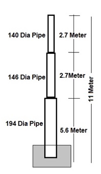
  • Calculate Pole foundation size and Wind pressure on Pole for following Details. * Tubular Street Light Pole (430V) height is 11 Meter which is in made with three different size of Tubular Pipe. * First Part is 2.7 meter height with 140mm diameter, * Second part of Pole is 2.7 meter height with 146 mm diameter and * Third part of Pole is 5.6 meter height with 194 mm diameter. * Weight of Pole is 241 kg and there is no any other Flood Light Fixtures Load on Pole. * Total Safety Factor is 2. * Wind zone category is 3. * The Pole is installed in open terrain with well scattered obstructions having height generally between 1.5 m to 10 m. * Foundation of pole is 700mm length, 700mm width and 1.95 meter depth. The Average weight of foundation concrete is 2500 Kg/M3.

1

CALCULATION:

 WIND PRESSURE ACCORDING TO LOCATION:

  • Wind Zone is 3 so Wind Speed as per following Table.

Basic Wind Speed-Vb (As per IS 802-Part1) Wind Zone Basic Wind Speed, vb m/s 1 33 2 39 3 44 4 47 5 50 6 55

  • Wind Speed (vb) = 44Mile/Second. * Co-efficient Factor (K0)=1.37 * K0 is a factor to convert 3 seconds peak gust speed into average speed of wind during 10 minutes period at a level of 10 meters above ground. K0 may be taken as 1.375. * The Pole is used for 430Vand wind zone is 3 so Risk Co-efficient (K1) as per following Table

Table 2 Risk Coefficient K1 for Different Reliability Levels and Wind Zones (As per IS 802-Part1) Reliability Level Wind Zone-1 Wind Zone-2 Wind Zone-3 Wind Zone-4 Wind Zone-5 Wind Zone-6 1 (Up to 400KV) 1 1 1 1 1 1 2 (Above 400KV) 1.08 1.1 1.11 1.12 1.13 1.14 3 (River Crossing) 1.17 1.22 1.25 1.27 1.28 1.3

  • Risk Co-efficient (K1) =1 * Terrain category (K2) for Open terrain with well scattered obstructions having height generally between 1.5 m to 10 m is 1 as per following Table * Terrain category (K2)=1

Terrain Roughness Coefficient, K2 (As per IS 802-Part1) Terrain Category Category 1 Category 2 Category 3 Exposed open terrain with no obstruction and in which the average height of any object surrounding the structure is less than 1.5 m. Open terrain with well scattered obstructions having height generally between 1.5 m to 10 m. Terrain with numerous closely spaced obstructions. Coefficient, K2 1.08 1 0.85

  • Reference Wind Speed (Vr)= Vb / K0. * Reference Wind Speed (Vr)= 44 / 1.37 =32 Mile/Second. * Design wind Speed (vd)= Vr X K1 X K2. * Design wind Speed (vd)= 32 X 1 X 1 =32 Mile/Second. * Design Wind Pressure (Pd)=0.6 x vd2 * Design Wind Pressure (Pd)=0.6 x (32)2 =614.4 N/m2 * Design Wind Pressure (Pd)=614.4/10 =61.4 Kg/m2

FOUNDATION DETAIL:

  • Total Weight =Pole Weight +Foundation Weight. * Total Weight = 241 +(0.7×0.7×1.95×2500) =2620.75 Kg * Stabilizing Moment = Total Weight X (Foundation Length/2) * Stabilizing Moment = 2620.75 X (0.7/2) = 920.41 Kg/Meter.

POLE DETAIL:

  • First Part of Pole (h1) = 2.7 meter * Diameter of First Part (d1) =140mm * Second Part of Pole (h2) = 2.7 meter * Diameter of Second Part (d2) =146mm * Third Part of Pole (h3) = 5.6 meter * Diameter of Third Part (d3) =194mm .

WIND PRESSURE ON POLE:

  • Overturning Moment due to the wind on 1st Part of the pole=pdxh1xd1x(h1/2+h2+h3)x0.6 * Overturning Moment due to the wind on 1st Part of the pole=61.4×2.7x(140/1000)x(2.7/2+2.7+5.61)x0.6 * Overturning Moment due to the wind on 1st Part of the pole=134.47 Kg/meter—I * Overturning Moment due to the wind on 2nd Part of the pole=pdxh2xd2x(h2/2+h3)x0.6 * Overturning Moment due to the wind on 2nd Part of the pole=61.4×2.7x(146/1000)x(2.7/2+5.61)x0.6 * Overturning Moment due to the wind on 2nd Part of the pole=112.76 Kg/meter.—-II * Overturning Moment due to the wind on 3rd Part of the pole=pdxh3xd3x(h3/2)x0.6 * Overturning Moment due to the wind on 3rd Part of the pole=61.4×5.6x(194/1000)x(5.6/2)x0.6 * Overturning Moment due to the wind on 3rd Part of the pole=112.14 Kg/meter.—III * Total Overturning Moment on Pole due to Wind=134.47+112.76+112.14=359.36 Kg/meter.

 SAFETY FACTOR:

  • Calculated Safety Factor= Stabilizing Moment / Total Overturning Moment on Pole. * Calculated Safety Factor=920.41/ 359.36 =2.56. * For safe Design Calculated Safety Factor > Safety Factor * Here Calculated Safety Factor (2.56) > Safety Factor (2) hence * Design is OK * B : If Calculated Safety Factor < Safety Factor then Change Foundation Size (Length, width or depth)

2. Calculate Street Light Pole’s Distance / Fixture Watt / Lighting Area

CALCULATE STREET LIGHT POLE’S FIXTURE WATT / LIGHTING AREA / DISTANCE

(1) CALCULATE DISTANCE BETWEEN EACH STREET LIGHT POLE:

Example: Calculate Distance between each streetlight pole having following Details,

  • Road Details: The width of road (w) is 11.5 Foot. * Pole Details: The height of Pole is 26.5 Foot. * Luminaire of each Pole: Wattage of Luminaries is 250 Watt, Lamp Out Put (LL) is 33200 Lumen, Required Lux Level (Eh) is 5 Lux, Coefficient of Utilization Factor (Cu) is 0.18, Lamp Lumen Depreciation Factor (LLD) is 0.8, Lamp Lumen Depreciation Factor (LLD) is 0.9. * Space Height Ratio should be less than 3.

Calculation:

  • Spacing between each Pole=(LLCULLDLDD) / EhW * Spacing between each Pole=(33200×0.18×0.8×0.9) / (5×11.5) * Spacing between each Pole= 75 Foot. * Space Height Ratio = Distance between Pole / Road width * Space Height Ratio = 3. Which is less than define value.

  • SPACING BETWEEN EACH POLE IS 75 FOOT.

(2) CALCULATE STREET LIGHT LUMINAIRE WATT:

Example: Calculate Streetlight Watt of each Luminaire of Street Light Pole having following Details,

  • Road Details: The width of road (w) is 7 Meter. Distance between each Pole (D) is 50 Meter. * Required Illumination Level for Street Light (L) is 6.46 Lux per Square Meter. Luminous efficacy is 24 Lumen/Watt. * Maintenance Factor (mf) 0.29, Coefficient of Utilization Factor (Cu) is 0.9.

Calculation:

  • Average Lumen of Lamp (Al) = 8663 Lumen. * Average Lumen of Lamp (Al) =(LxWxD) / (mfxcu) * Average Lumen of Lamp (Al)= (6.46x7x50) / (0.29×0.9) * Average Lumen of Lamp (Al)=8663 Lumen. * Watt of Each Street Light Luminar = Average Lumen of Lamp / Luminous efficacy * Watt of Each Street Light Laminar = 8663 / 24

  • WATT OF EACH STREET LIGHT LUMINAIRE = 361 WATT

(3) CALCULATE REQUIRED POWER FOR STREET LIGHT AREA:

Example: Calculate Streetlight Watt of following Street Light Area,

  • Required Illumination Level for Street Light (L) is 6 Lux per Square Meter. * Luminous efficacy (En) is 20 Lumen per Watt. * Required Street Light Area to be illuminated (A) is 1 Square Meter.

Calculation:

  • Required Streetlight Watt = (Lux per Sq.Meter X Surface Area of Street Light) / Lumen per Watt. * Required Streetlight Watt = (6 X 1) / 20.

  • REQUIRED STREETLIGHT WATT = 0.3 WATT PER SQUARE METER.

(5) Illumination / STREET LIGHT / FLOOD LIGHT:

3. Calculate No of Street Light Poles

CALCULATE NO OF STREET LIGHT POLES

TYPICAL CALCULATION OF ROAD LIGHTING:

  • Luminaries are properly selected and mounted on a location most feasible and effective with minimum cost. For a 230 volts system, a voltage drop of 5% is allowed although in extreme cases 15% voltage drop is sometimes tolerated. 3

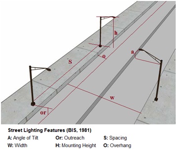
  • Street illumination level in Lux (E)=(Al x (cu x mf)) / (w x d) * E = The illumination in Lux * w = Width of the roadway * d = Distance between luminaries * cu = Coefficient of utilization. Which is dependent on the type of fixture, mounting height, width of roadway and the length of mast arm of outreach? * Al = Average lumens, Al = (E x w x d) / Cu x mf * The typical value of Al is * 20500 lumens for 400 watts * 11500 lumens for 250 watts * 5400 lumens for 125 watts * The value of Al varies depending upon the type of lamp specified. * mf : It is the maintenance factor (Normally 0.8 to 0.9)

 (1) CALCULATE LAMP WATT FOR STREET LIGHT POLE:

  • Calculate Lamp Lumen for street Light Pole having Road width of 7 meter, distance between two Pole is 50 meter, Maintenance factor is 0.9, Coefficient of utilization factor is 0.29, light pedestrian traffic is medium and Vehicular traffic is very light and Road is concrete road. Solution: From Above table Recommended of illumination (E) in Lux is 6.46 per sq. meter. w = 7.00 meters , d = 50 meters , mf = 0.9, cu = 0.29 To decide Lamp Watt It is necessary to calculate Average Lumens of Lamp (Al). * Average Lumen of Lamp (Al)=(E x w x d) / Cu x mf * Al=(6.46x7x50)/(0.29×0.9)= 8662.83 Average lumen Lamp lumen of a 250 watts lamp is 11,500 lm which is the nearest value to 8662.83 lumen. Therefore, a 250 watts lamp is acceptable. Let’s Computing for the actual illumination E for 250 Watt Lamp * Illumination (E)=(Al x (cu x mf)) / (w x d) * E= (11500×0.29×0.9) / (7×50) = 8.57 lumen per sq meter. Conclusion: Actual illumination (E) for 250 Watt is 8.57 lumen per sq meter which is higher than recommended illumination (E) 6.46.

  • HENCE 250 WATT GIVES ADEQUATELY LIGHTING.

 (2) CALCULATE SPACING BETWEEN TWO LIGHT POLES:

  • Calculate Space between Two Pole of Street Light having Fixture Watt is 250W , Lamp output of the Lamp (LL) is 33200 lumens , Required Lux Level (E) is 5 lux , Width of the road (W) = 11.48 feet (3.5 M),Height of the pole (H) = 26.24 feet (8 M) ,Coefficient of utilization (CU) = 0.18, Lamp Lumen Depreciation Factor (LLD) = 0.8 ,Luminaries dirt Depreciation Factor (LDD) = 0.9 Solution: * Luminaries Spacing (S) = (LLxCUxLLDxLDD) / (ExW) * Luminaries Spacing (S) = (33200×0.18×0.9×0.8) / (5×11.48)

  • LUMINARIES SPACING (S) = 75 FEET (23 METERS)

 (3) CALCULATION OF THE ALLOWED ILLUMINATION TIME:

  • The allowed illumination time in hours T = k.t.1000/E. * Where: k = extension factor * t = permissible time in hours at 1000 lux, unfiltered daylight * E = luminance (lx)

Extension Factor Lamp Extension Factor Incandescent lamps, 2.7 to 3.2 Halogen reflector lamps 2.5 to 3.5 Halogen capsules 2.5 to 3.5 High-pressure metal-halide 1.1 to 2.1 High-pressure sodium lamps 4 Fluorescent lamps 1.9 to 2.7

  • Example: * In sunlight (100000 lux) and extension factor 1: The permissible illumination time (T) =1 x 70 x 1000/100 000 = 0.7 hour. * In halogen light (200 lux) and extension factor 2.3: The permissible illumination time (T) = 2.3 x 70 x 1000/200 = 805 hours. * In UV-filtered halogen light (200 lux) and extension factor 3.5: The permissible illumination time (T) = 3.5 x 70 x 1000/200 = 1225 hours.

 (4) CALCULATE UNIFORMITY RATIO:

  • Once luminaries spacing has been decided It is necessary to check the uniformity of light distribution and compare this value to the selected lighting * Uniformity Ratio ( UR) = Eav /Emin * Eav= average maintained horizontal luminance * Emin = maintained horizontal luminance at the point of minimum illumination on the pavement

 (5) ENERGY SAVING CALCULATIONS:

  • At a simplistic level, the cost of running a light is directly related to the wattage of the globe plus any associated ballast or transformer. The higher the wattage, the higher the running cost and it is a straightforward calculation to work out the running cost of lamp over its lifetime: * Running cost = cost of electricity in $/kWh x wattage of lamp x lifetime in hours.

 CALCULATE LUX LEVEL FOR STREET LIGHTING

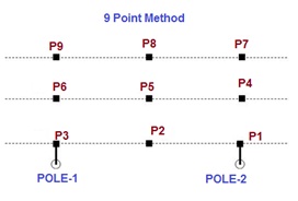
  • The Average Lux Level of Street Light is measured by 9 point method. Make two equal quadrants between two Street light poles. on the lane of light poles( one side pole to road). * We have 3 points P1,P2 and P3 under the light pole then P4 & P7 are points opposite pole 1 or Point P3 same is applicable for P6 and P9 for Pole 2. * The average lux = [(P1+P3+P7+P9)/16]+[(P2+P6+P8+P4)/8]+[P5/4]

 2

(5) Illumination / STREET LIGHT / FLOOD LIGHT:

4. Calculate No of Lighting Fixtures / Lumen for Indoor Lighting

CALCULATE NO OF STREET LIGHT POLES

TYPICAL CALCULATION OF ROAD LIGHTING:

  • Luminaries are properly selected and mounted on a location most feasible and effective with minimum cost. For a 230 volts system, a voltage drop of 5% is allowed although in extreme cases 15% voltage drop is sometimes tolerated. 3

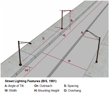
  • Street illumination level in Lux (E)=(Al x (cu x mf)) / (w x d) * E = The illumination in Lux * w = Width of the roadway * d = Distance between luminaries * cu = Coefficient of utilization. Which is dependent on the type of fixture, mounting height, width of roadway and the length of mast arm of outreach? * Al = Average lumens, Al = (E x w x d) / Cu x mf * The typical value of Al is * 20500 lumens for 400 watts * 11500 lumens for 250 watts * 5400 lumens for 125 watts * The value of Al varies depending upon the type of lamp specified. * mf : It is the maintenance factor (Normally 0.8 to 0.9)

 (1) CALCULATE LAMP WATT FOR STREET LIGHT POLE:

  • Calculate Lamp Lumen for street Light Pole having Road width of 7 meter, distance between two Pole is 50 meter, Maintenance factor is 0.9, Coefficient of utilization factor is 0.29, light pedestrian traffic is medium and Vehicular traffic is very light and Road is concrete road. Solution: From Above table Recommended of illumination (E) in Lux is 6.46 per sq. meter. w = 7.00 meters , d = 50 meters , mf = 0.9, cu = 0.29 To decide Lamp Watt It is necessary to calculate Average Lumens of Lamp (Al). * Average Lumen of Lamp (Al)=(E x w x d) / Cu x mf * Al=(6.46x7x50)/(0.29×0.9)= 8662.83 Average lumen Lamp lumen of a 250 watts lamp is 11,500 lm which is the nearest value to 8662.83 lumen. Therefore, a 250 watts lamp is acceptable. Let’s Computing for the actual illumination E for 250 Watt Lamp * Illumination (E)=(Al x (cu x mf)) / (w x d) * E= (11500×0.29×0.9) / (7×50) = 8.57 lumen per sq meter. Conclusion: Actual illumination (E) for 250 Watt is 8.57 lumen per sq meter which is higher than recommended illumination (E) 6.46.

  • HENCE 250 WATT GIVES ADEQUATELY LIGHTING.

 (2) CALCULATE SPACING BETWEEN TWO LIGHT POLES:

  • Calculate Space between Two Pole of Street Light having Fixture Watt is 250W , Lamp output of the Lamp (LL) is 33200 lumens , Required Lux Level (E) is 5 lux , Width of the road (W) = 11.48 feet (3.5 M),Height of the pole (H) = 26.24 feet (8 M) ,Coefficient of utilization (CU) = 0.18, Lamp Lumen Depreciation Factor (LLD) = 0.8 ,Luminaries dirt Depreciation Factor (LDD) = 0.9 Solution: * Luminaries Spacing (S) = (LLxCUxLLDxLDD) / (ExW) * Luminaries Spacing (S) = (33200×0.18×0.9×0.8) / (5×11.48)

  • LUMINARIES SPACING (S) = 75 FEET (23 METERS)

 (3) CALCULATION OF THE ALLOWED ILLUMINATION TIME:

  • The allowed illumination time in hours T = k.t.1000/E. * Where: k = extension factor * t = permissible time in hours at 1000 lux, unfiltered daylight * E = luminance (lx)

Extension Factor Lamp Extension Factor Incandescent lamps, 2.7 to 3.2 Halogen reflector lamps 2.5 to 3.5 Halogen capsules 2.5 to 3.5 High-pressure metal-halide 1.1 to 2.1 High-pressure sodium lamps 4 Fluorescent lamps 1.9 to 2.7

  • Example: * In sunlight (100000 lux) and extension factor 1: The permissible illumination time (T) =1 x 70 x 1000/100 000 = 0.7 hour. * In halogen light (200 lux) and extension factor 2.3: The permissible illumination time (T) = 2.3 x 70 x 1000/200 = 805 hours. * In UV-filtered halogen light (200 lux) and extension factor 3.5: The permissible illumination time (T) = 3.5 x 70 x 1000/200 = 1225 hours.

 (4) CALCULATE UNIFORMITY RATIO:

  • Once luminaries spacing has been decided It is necessary to check the uniformity of light distribution and compare this value to the selected lighting * Uniformity Ratio ( UR) = Eav /Emin * Eav= average maintained horizontal luminance * Emin = maintained horizontal luminance at the point of minimum illumination on the pavement

 (5) ENERGY SAVING CALCULATIONS:

  • At a simplistic level, the cost of running a light is directly related to the wattage of the globe plus any associated ballast or transformer. The higher the wattage, the higher the running cost and it is a straightforward calculation to work out the running cost of lamp over its lifetime: * Running cost = cost of electricity in $/kWh x wattage of lamp x lifetime in hours.

 CALCULATE LUX LEVEL FOR STREET LIGHTING

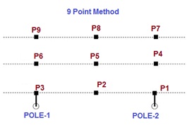
  • The Average Lux Level of Street Light is measured by 9 point method. Make two equal quadrants between two Street light poles. on the lane of light poles( one side pole to road). * We have 3 points P1,P2 and P3 under the light pole then P4 & P7 are points opposite pole 1 or Point P3 same is applicable for P6 and P9 for Pole 2. * The average lux = [(P1+P3+P7+P9)/16]+[(P2+P6+P8+P4)/8]+[P5/4]

 2

Cover image
(5) Illumination / STREET LIGHT / FLOOD LIGHT:

5. Calculate Lighting Fixture’s Beam Angle and Lumen

CALCULATE LIGHTING FIXTURE’S BEAM ANGLE AND LUMEN

EXAMPLE 1: CALCULATE LIGHTING FIXTURE’S LUMEN AND DIAMETER OF ILLUMINATION AT SURFACE HAVING FOLLOWING DETAILS.

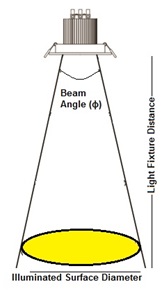
  • Required illumination at surface is 1390 Lux * The distance from Lighting Fixture to illumination surface is 3 Meter. * The Fixture Beam Angle is 10 Degree.

1234

CALCULATION:

  • Required Lux at Surface (E2) =1390 Lux. * Distance between Lighting Fixture and Surface (D) = 3 Meter. * Fixture Beam Angle (ϕ)= 10° * Irradiance at 1.0 meter (E1)= DxDxE2 * Irradiance at 1.0 meter (E1)=1390x3x3 =12510 Lumen / M2 * Irradiance at 1.0 meter (E1)= 12510 Lumen / M2 * Solid Angle of The Lamp (Ω) =2xπx(1-COS(ϕ/2)) * Solid Angle of The Lamp (Ω) =2×3.14x(1-COS(10/2)) =6.28x(1-0.996) * Solid Angle of the Lamp (Ω) =0.0239 Steradian. * Required Lumen of Lighting Fixtures= E1x Ω * Required Lumen of Lighting Fixtures=12510×0.0239 * Required Lumen of Lighting Fixtures=299 Lumen. * Illumination Diameter at surface =0.018xDx ϕ * Illumination Diameter at surface =0.018x3x10 * Illumination Diameter at surface =0.54 Meter.

EXAMPLE 2: CALCULATE LIGHTING FIXTURE’S BEAM ANGLE AND ILLUMINATION DIAMETER AT SURFACE HAVING FOLLOWING DETAILS.

  • Required illumination at surface is 22 Lux * Lighting Fixture Lumen is 1547 Lumen. * The distance from Lighting Fixture to illumination surface is 4 Meter.

CALCULATION:

  • Required Lux at Surface (E2) =22 Lux. * Distance between Lighting Fixture and Surface (D) = 4 Meter. * Irradiance at 1.0 meter (E1)= DxDxE2 * Irradiance at 1.0 meter (E1)=4x4x22 =352 Lumen / M2 * Irradiance at 1.0 meter (E1)= 352 Lumen / M2 * Solid Angle of The Lamp (Ω) = Lumen of Lighting Fixtures / E1 * Solid Angle of the Lamp (Ω) =1547 / 352 * Solid Angle of the Lamp (Ω) =4.394 Steradian. * Solid Angle of The Lamp (Ω) =2xπx(1-COS(ϕ/2)) * 39 =2×3.14x(1-COS(ϕ/2)) * Fixture Beam Angle (ϕ)=145° * Illumination Diameter at surface =0.018xDx ϕ * Illumination Diameter at surface =0.018x4x145 * Illumination Diameter at surface =10.44 Meter.

EXAMPLE 3: CALCULATE LUX LEVEL AND ILLUMINATION DIAMETER AT SURFACE HAVING FOLLOWING DETAILS.

  • Lighting Fixture Lumen is 299 Lumen. * The distance from Lighting Fixture to illumination surface is 3 Meter. * The Fixture Beam Angle is 10 Degree.

CALCULATION:

  • Required Lux at Surface (E2) =1390 Lux. * Distance between Lighting Fixture and Surface (D) = 3 Meter. * Fixture Beam Angle (ϕ)= 10° * Solid Angle of The Lamp (Ω) =2xπx(1-COS(ϕ/2)) * Solid Angle of The Lamp (Ω) =2×3.14x(1-COS(10/2)) =6.28x(1-0.996) * Solid Angle of the Lamp (Ω) =0.0239 Steradian. * Lumen of Lighting Fixtures= E1x Ω * 299= E1x0.0239 * Irradiance at 1.0 meter (E1)= Lumen of Lighting Fixtures / Ω * Irradiance at 1.0 meter (E1)=299 / 0.0239 * Irradiance at 1.0 meter (E1)= 12506 Lumen / M2 * Lux at Surface (E2) = E1 / (DxD) * Lux at Surface (E2) =12506 / (3×3) * Lux at Surface (E2) =1389.5 Lux * Illumination Diameter at surface =0.018xDx ϕ * Illumination Diameter at surface =0.018x3x10 * Illumination Diameter at surface =0.54 Meter.
(5) Illumination / STREET LIGHT / FLOOD LIGHT:

6. Simple Calculation of Flood Light, Facade Light, Street Light & Signage Light-(Part-2)

SIMPLE CALCULATION OF FLOOD LIGHT, FACADE LIGHT, STREET LIGHT & SIGNAGE LIGHT-(PART2)

(B) FACADE LIGHTING:

  • Normally Facade Lighting are used to illuminate Building area from Outer Side. * There are three factor should be consider while designing of outdoor Facade Lighting.
  1. Setback 2. Spacing 3. Aiming
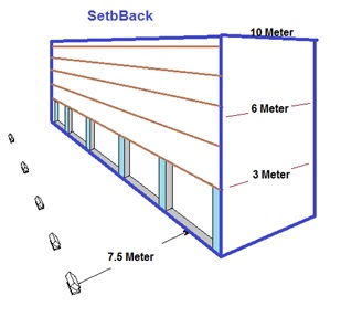
  1. SETBACK:
  • The recommended setback should be 3/4 times the building height. * If a building is 10 Meter tall, the recommended setback is 7.5 Meter from the building. * If the locating the floodlight closer to the building will sacrifice uniformity and If setting it further back will result in loss of efficiency. * Setback distance = 3/4 x Building height * Setback distance =3/4 x (10 Meter) = 7.5 Meter 

a

  1. SPACING:
  • Spacing of floodlights should not be exceeding two times the setback distance. * If the setback is 7.5 Meter the floodlights should not be placed more than 15 Meter apart. * Spacing = 2 x setback distance * Spacing=2 x 5 = 15 Meter

b

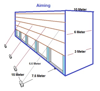
  1. AIMING:
  • The floodlight should be aimed at least 2/3 the height of the building. * If a building is 10 Meter high, the recommended aiming point is approximately 6.6 Meter high. * After installation aiming can be adjusted to produce the best fine appearance. * Aiming Point = 2/3 x Building Height. * Aiming Point =2/3 (10 Meter) = 6.6 Meter high

c

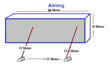
(C) SINAGE LIGHTING:

  • Normally Sinage Lighting are used to illuminate Sinage Board either Floor Mounted or Pole Mounted * There are three factor should be consider while designing of Sinage Board Lighting.
  1. Setback 2. Spacing 3. Aiming
  1. SETBACK:
  • When using floodlights to light a sinage, the setback should be 3/4 the sign height * If the sinage height is 18 Meter then the setback distance would be 13.5 Meter. * If the floodlight closer to sinage will sacrifice uniformity while setting it further back will in a loss of efficiency. * Setback distance = 3/4 x sinage height * Setback distance =3/4 (18 Meter) = 13.5 Meter.

d

  1. SPACING:
  • The spacing floodlights should not be exceed two times the setback distance. * If the setback is 13.5 Meter, the floodlights should not be placed more than 27 Meter apart. * Spacing = 2 x setback distance. * Spacing = 2 x 5 (Meter) = 27 Meter.

e

  1. AIMING:
  • The floodlight should be aimed at least 2/3 up the sign. * If a sign is 18 Meter tall, then the floodlight should be aimed approximately 12 Meter high. * Aiming can be adjusted to produce the best appearance. * Mounting a full or upper visor to the floodlight can reduce unwanted glare. * Aiming point = 2/3 x sign height * Aiming point =2/3 (18 Meter) = 12 Meter high

f

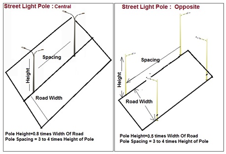
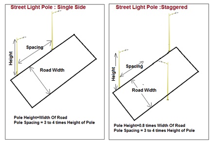
STREET LIGHT POLE HEIGHT & SPACING (AS PER CPWD):

  • There are four type of Street Light Pole arrangement. * One side Type. * Staggered Type. * Opposite Type. * Central Type. * As per CPWD we can calculate Pole Height and Spacing as per under

(1) ONE SIDE STREET LIGHT POLE ARRANGEMENT.

  • Pole Height = Width of Road. * Pole Spacing = 3 to 4 Times Height of Pole. * If the Road width is 8 Meter than * Pole Height=8 Meter * Pole Spacing =24 to 32 Meter.

g

(2) STAGGERED TYPE STREET LIGHT POLE ARRANGEMENT.

  • Pole Height = 0.8 time Width of Road. * Pole Spacing = 3 to 4 Times Height of Pole. * If the Road width is 8 Meter than * Pole Height=6.4 Meter * Pole Spacing =24 to 32 Meter.

h

(3) OPPOSITE SIDE STREET LIGHT POLE ARRANGEMENT.

  • Pole Height = 0.5 time Width of Road. * Pole Spacing = 3 to 4 Times Height of Pole. * If the Road width is 8 Meter than * Pole Height=6.4 Meter * Pole Spacing =24 to 32 Meter.

(4) CENTRAL STREET LIGHT POLE ARRANGEMENT.

  • Pole Height = 0.8 time Width of Road. * Pole Spacing = 3 to 4 Times Height of Pole. * If the Road width is 8 Meter than * Pole Height=4 Meter * Pole Spacing =24 to 32 Meter.
(5) Illumination / STREET LIGHT / FLOOD LIGHT:

7. Simple Calculation of Flood Light, Facade Light, Street Light & Signage Light-(Part-1)

SIMPLE CALCULATION OF FLOOD LIGHT, FACADE LIGHT, STREET LIGHT & SIGNAGE LIGHT-(PART1)

INTRODUCTION:

  • Outdoor Lighting can be classified according to the location where it can be installed or its function which use for highlight landscape area. * Outdoor Lighting can be classified as
  1. Flood Lighting, 2. Facade Lighting and 3. Signage Lighting 4. Street Light

(A) GENERAL OUTDOOR FLOOD LIGHTING:

  • Normally Pole mounted floodlights are used to illuminate general lighting area of parking lots and storage yards. * There are three factor should be consider while designing of outdoor flood lighting.
  1. Mounting Height. 2. Spacing 3. Aiming Distance. 4. Horizontal Aiming.
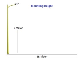
  1. Mounting Height:
  • Mounting height should be one half the distance across the area to be lighted. * If the area to be lighted is 16 Meter, the lowest recommended mounting height is 8 Meter. * Mounting height = 1/2 distance to be lighted * 1/2 (16 Meter.) = 8 Meter. 

1

  1. Spacing:
  • When more than one Luminar / pole is required than distance between two adjacent luminar / Pole is 4 times Mounting height of luminar /pole. * If the mounting height of luminar /Pole is 8 Meter than distance between adjacent Luminar is 32 Meter. * Pole Spacing = 4 x mounting height. * 4 (8 Meter pole) = 32 Meter between poles

2

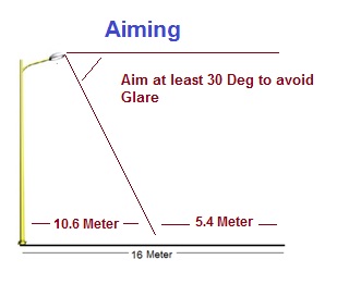
  1. Vertical Aiming:
  • The fixture should be aimed 2/3 of the distance across the area to be lighted and at least 30 degrees below horizontal. * If the area to be lighted is 16 Meter across, the recommended aiming point is 10.6 Meter. * Aiming point = 2/3 Distance to be lighted. * 2/3 (16 Meter) = 10.6 Meter aiming point * To minimize glare, the recommended aiming point distance should never exceed twice the mounting height. * If a pole is 8 Meter high, the vertical aiming point should not exceed 16 Meter. * 2 (8 Meter mounting height) = 16 Meter. 

3

  1. Horizontal Aiming:
  • When two floodlights is mounted to a single pole then horizontal aiming also must be considered. * Each floodlight should be vertically aimed according to the two-thirds rule. * The floodlights should be aimed up to 90 degrees apart. 

4