Site logo
Electrical Engineering Academy

4. Calculate Cable Size and Voltage Drop

CALCULATE CABLE SIZE AND VOLTAGE DROP

CALCULATE CABLE SIZE AND VOLTAGE DROP:

CALCULATE VOLTAGE DROP AND SIZE OF ELECTRICAL CABLE FOR FOLLOWING DATA.

  • Electrical Details: Electrical Load of 80KW, Distance between Source and Load is 200 Meter, System Voltage 415V Three Phase, Power Factor is 0.8,Permissible Voltage drop is 5%, Demand Factor is 1, * Cable Laying Detail: Cable is directed buried in Ground in trench at the depth of 1 meter. Ground Temperature is approximate 35 Deg. No of Cable per Trench is 1. No of Run of Cable is 1 Run. * Soil Details: Thermal Resistivity of Soil is not known. Nature of Soil is Damp Soil.

CALCULATION:

  • Consumed Load= Total Load x Demand Factor * Consumed Load in KW= 80 x 1 =80KW * Consumed Load in KVA= KW/P.F * Consumed Load in KVA =80/0.8=100KVA * Full Load Current= (KVAx1000) / (1.732xVoltage) * Full Load Current= (100×1000) / (1.732×415) = 139Amp. * Calculating Correction Factor of Cable from following data : * Temperature Correction Factor (K1) When Cable is in Air is

Temperature Correction Factor in Air :K1

Ambient Temp©

Insulation

PVC

XLPE/EPR

10

1.22

1.15

15

1.17

1.12

20

1.12

1.08

25

1.06

1.04

35

0.94

0.96

40

0.87

0.91

45

0.79

0.87

50

0.71

0.82

55

0.61

0.76

60

0.5

0.71

65

0

0.65

70

0

0.58

75

0

0.5

80

0

0.41

  • Ground Temperature Correction Factor (K2):

Ground Temperature Correction Factor:K2

Ground Temp©

Insulation

PVC

XLPE/EPR

10

1.1

1.07

15

1.05

1.04

20

0.95

0.96

25

0.89

0.93

35

0.77

0.89

40

0.71

0.85

45

0.63

0.8

50

0.55

0.76

55

0.45

0.71

60

0

0.65

65

0

0.6

70

0

0.53

75

0

0.46

80

0

0.38

  • Thermal Resistance Correction Factor (K4) for Soil (When Thermal Resistance of Soil is known):

Ther.Resi Correction Factor: K4

Soil Thermal Resistivity: 2.5 KM/W

Resistivity

K3

1

1.18

1.5

1.1

2

1.05

2.5

1

3

0.96

  • Soil Correction Factor(K4) of Soil (When Thermal Resistance of Soil is not known):

Soil Correction Factor:K4

Nature of Soil

K3

Very Wet Soil

1.21

Wet Soil

1.13

Damp Soil

1.05

Dry Soil

1

Very Dry Soil

0.86

  • Cable Depth Correction Factor (K5):

Cable Depth Factor (K5)

Laying Depth(Meter)

Rating Factor

0.5

1.1

0.7

1.05

0.9

1.01

1

1

1.2

0.98

1.5

0.96

  • Cable Distance correction Factor (K6):

Cable Distance Correction Factor(K6)

No of Circuit

Nil

cable Diameter

0.125m

0.25m

0.5m

1

1

1

1

1

1

2

0.75

0.8

0.85

0.9

0.9

3

0.65

0.7

0.75

0.8

0.85

4

0.6

0.6

0.7

0.75

0.8

5

0.55

0.55

0.65

0.7

0.8

6

0.5

0.55

0.6

0.7

0.8

  • Cable Grouping Factor ( No of Tray Factor) (K7):

No of Cable/Tray

(Cable Grouping factor K7 )==No of Tray

1

2

3

4

6

8

1

1

1

1

1

1

1

2

0.84

0.8

0.78

0.77

0.76

0.75

3

0.8

0.76

0.74

0.73

0.72

0.71

4

0.78

0.74

0.72

0.71

0.7

0.69

5

0.77

0.73

0.7

0.69

0.68

0.67

6

0.75

0.71

0.7

0.68

0.68

0.66

7

0.74

0.69

0.675

0.66

0.66

0.64

8

0.73

0.69

0.68

0.67

0.66

0.64

  • According to above Detail correction Factors are * Ground Temperature Correction Factor (K2) =0.89 * Soil Correction Factor (K4)=1.05 * Cable Depth Correction Factor (K5)=1.0 * Cable Distance correction Factor (K6)=1.0 * Total De rating Factor= k1x k2 x k3 x K4 x K5 x K6 x K7 * Total De rating Factor= 0.93

SELECTION OF CABLE:

  • For selection of Proper Cable following Conditions should be satisfied * (1) Cable De rating Amp should be higher than Full Load Current of Load. * (2) Cable Voltage Drop should be less than Defined Voltage drop. * (3) No of Run of Cable >= (Full Load current / Cable De rating Current). * (4) Cable Short Circuit Capacity should be higher than System S.C Capacity at that Point.

SELECTION OF CABLE CASE (1):

  • Let’s Select 3.5Core 70 Sq.mm cable for Single run. * Current Capacity of 70 Sq.mm cable is 170Amp,Resistance=0.57Ω/Km and Reactance=0.077 mho/Km * Total De rating Current of 70 Sq.mm Cable= 170×0.93 =159 Amp. * Voltage Drop of Cable= (1.732x Current x (RcosǾ+jsinǾ) x Cable Lengthx100) / (Line Voltage x No of Runx1000) * Voltage Drop of Cable= (1.732x139x(0.57×0.8+0.077×0.6)x200x100)/(415x1x1000)=5.8% * Voltage Drop of Cable=5.8% * Here Voltage drop for 70 Sq.mm Cable (5.8%) is higher than Define Voltage drop (5%) so either select higher size of cable or Increase no of Cable Runs. * If we Select 2 No’s of Run than Voltage drop is 2.8% which is within limit (5%) but to use 2 no’s of Run of cable of 70 Sq.mm Cable is not economical so It is necessary to use next higher size of Cable.

SELECTION OF CABLE CASE (2):

  • Let’s Select 3.5Core 95 Sq.mm cable for Single run, S.C Capacity =8.2KA. * Current Capacity of 95 Sq.mm cable is 200Amp,Resistance=0.41Ω/Km and Reactance=0.074 mho/Km * Total De rating Current of 70 Sq.mm Cable= 200×0.93 =187 Amp. * Voltage Drop of Cable= (1.732x139x(0.41×0.8+0.074×0.6)x200x100)/(415x1x1000)=2.2% * Voltage D…
(2) PANEL / BUS BAR / RELAY:

1. Calculate Size of Bus bar & Panel Design

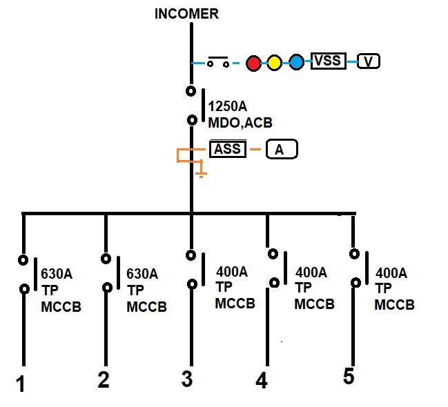
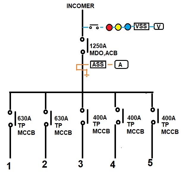
CALCULATE DIMENSION OF ELECTRICAL PANEL FROM SLD

INTRODUCTION:

  • In Designing Stage , We need to calculate approximate Dimension of Electrical Panel to conclude Dimension of Electrical Room and Total Space requirement of Electrical Services. * Dimension of Electrical Panel’s is calculated from Electrical SLD. * Dimension of Electrical Panel mainly depends on
  1. Size of Main Incoming and Outgoing Circuit Barker. 2. No of Outgoing Circuit Breakers. 3. Panel’s Form Factor. 4. Type of Panel (Indoor / Outdoor). 5. Cable connection in Panel (Front Side / Back side of Panel). 6. Installation of Circuit Breaker (Horizontal / Vertical) 7. Height of Panel should not be more than 2200mm Due to Operation of Upmost Switchgear.

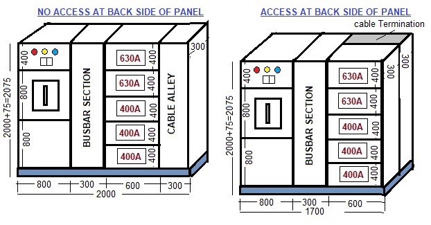
GENERAL SWITCHGEAR ARRANGEMENTS IN PANEL 

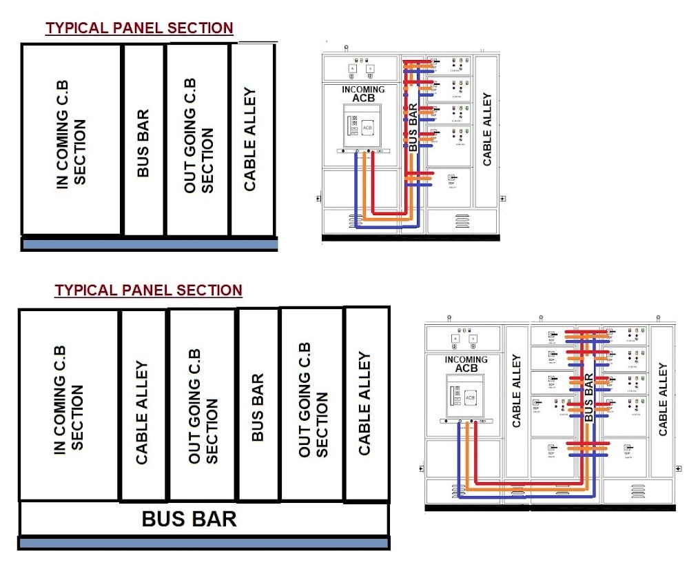
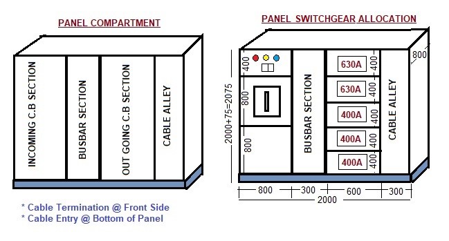
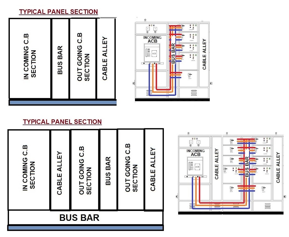
  • There are four compartments in Electrical Panel.
  1. Incoming Section 2. Outgoing Section 3. Busbar Chamber 4. Cable Alley.

1

FACTORS TO BE CONSIDERED TO CALCULATE DIMENSION OF PANEL:

  • Dimension of Panel mainly depends on following factors.
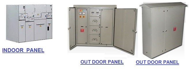
  1. TYPE OF PANEL (INDOOR / OUTDOOR):
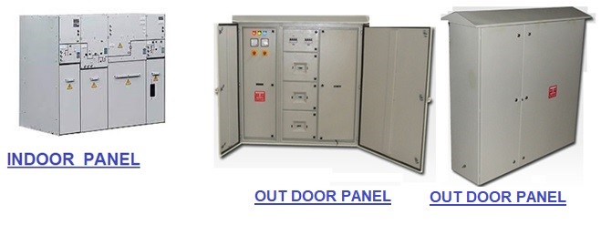
  • Depth of Panel is depending on Type of Panel. * If We have Indoor Type of Panel and there are no any issue regarding Water seepages near Panel than Double Door type of Panel is not required. * In Out Door Type Panel construction is mostly Double Door Type. * For Double Door Construction required more 100mm Panel Depth than actual .

2

  1. FORM FACTOR OF PANEL:
  • Type of Form Factor decide Dimension of Panel. * For Same type and same rating of Switchgear Form 1 required less space compared to Form 2A, 2B, 3A, 3B, 4A, 4B.
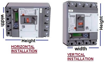
  1. POSITION OF SWITCH GEAR INSTALLATION
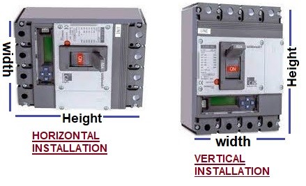
  • Panel’s Width and Height mostly depends on Position of Switchgear Installation. * If we installed Switchgear in vertical Position than Height of Panel is increased. * If we installed Switchgear in horizontal position than with of Panel is increased. * Most of manufacture prefer Horizontal position of Switchgear to easy termination of Incoming and Outgoing of Switchgear to Busbar.

3

  1. HEIGHT OF PANEL
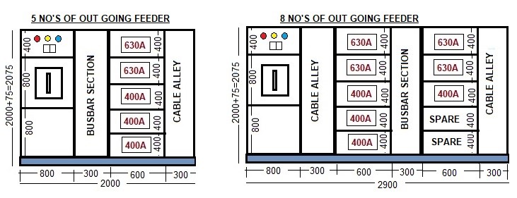
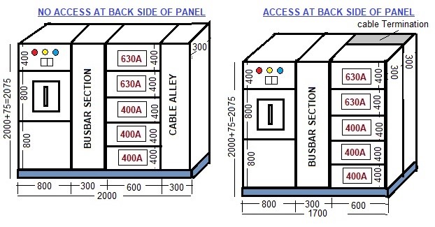
  • Height of Panel should not more than 2200mm for easy operation of upmost Switchgear in Panel. * This 2200MM height concert increase width of Panel if we have multiple number of outgoing.

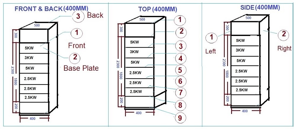
  • If we have 5 Nos of outgoing than it may require one No of Colum Section of Panel (400×5=2000mm).

  • But if we have 8 No’s of outgoing than we required two no of Colum Section in one Section 4 no of Outgoing Switchgear and in second Colum section for 3 no of Switch gear. 1 no of More cable alley section (300mm) required for cable termination.

4

  1. CABLE TERMINATION IN PANEL (FRONT SIDE / BACK SIDE)
  • Front Side Cable Termination: If We Installed Panel In front of wall than Panel Back Side is not accessible hence We need Cable Termination on front side of Panel for this we need Cable Alley of 300mm for Cable Termination. * This arrangement increase width of 300mm for panel but depth of panel will not increase. * Back Side Cable Termination: If We Installed Panel at some distance from wall than Panel Back Side is accessible hence, we may do Cable Termination on back side of Panel for this arrangement we need more 300mm depth for Cable Termination. * This arrangement will not increase width of panel but depth of panel will not increase 300mm.

5

GENERAL COMPARTMENT SIZE FOR VARIOUS SWITCHGEAR IN PANEL.

SIZE OF MCB / MCCB COMPARTMENT (CABLE CONNECTIONS ARE IN FRONT OF PANEL)

MCB / MCCB Size

Position

Width (mm)

Height (mm)

Depth (mm)

Up to 63A

Horizontal

300

275

300

63A to 100A

Horizontal

350

300

300

125A to 250A

Horizontal

350 to 400

300 to 350

300 to 350

400A to 630A

Horizontal

600

400

350 to 400

MCCB 800A

Horizontal

600

600

700

MCCB 1250A to 3200A

Horizontal

800

850

1000

  • Cable Connections are in front side of Panel, If Cable Connection are in Back Side of Panel add 300mm in Depth of Panel

  • Cable Termination Space in Panel (From Cable Entry at Panel to Termination Location) Up to 800A =more than 400 mm, above 800A It should be more than 800mm.

SIZE OF ACB COMPARTMENT (CABLE CONNECTIONS ARE IN FRONT OF PANEL)

ACB Size

Position

Width (mm)

Height (mm)

Depth (mm)

800A

Horizontal

700

800

800

1600A

Horizontal

800

800

850

ACB up to 3200A

Horizontal

800

850

1000

ACB Above 3200A

Horizontal

1400

1000

1200

For Cable Entry from Bottom of Panel=Min 700mm Height from Bottom to Cable Termination

  • Cable Termination Space in Panel (From Cable Entry at Panel to Termination Location) Up to 800A =more than 400 mm, Above 800A It should be more than 800mm.

SIZE OF SFU COMPARTMENT (CABLE CONNECTIONS ARE IN FRONT OF PANEL)

SFU Size

Position

Width (mm)

Height (mm)

Depth (mm)

125A

Horizontal

400

350

300

200A

Horizontal

400

350

300

200A

Horizontal

400

400

300

  • Cable Connections are in front side of Panel , If Cable Connection are in Ba…

2. Calculate IDMT over Current Relay Setting (50/51)

CALCULATE IDMT OVER CURRENT RELAY SETTING (50/51)

  • Calculate setting of IDMT over Current Relay for following Feeder and CT Detail * Feeder Detail: Feeder Load Current 384 Amp, Feeder Fault current Min11KA and Max 22KA. * CT Detail: CT installed on feeder is 600/1 Amp. Relay Error 7.5%, CT Error 10.0%, CT over shoot 0.05 Sec, CT interrupting Time is 0.17 Sec and Safety is 0.33 Sec. * IDMT Relay Detail: * IDMT Relay Low Current setting: Over Load Current setting is 125%, Plug setting of Relay is 0.8 Amp and Time Delay (TMS) is 0.125 Sec, Relay Curve is selected as Normal Inverse Type. * IDMT Relay High Current setting :Plug setting of Relay is 2.5 Amp and Time Delay (TMS) is 0.100 Sec, Relay Curve is selected as Normal Inverse Type

CALCULATION OF OVER CURRENT RELAY SETTING:

(1) LOW OVER CURRENT SETTING: (I>)

  • Over Load Current (In) = Feeder Load Current X Relay setting = 384 X 125% =480 Amp * Required Over Load Relay Plug Setting= Over Load Current (In) / CT Primary Current * Required Over Load Relay Plug Setting = 480 / 600 = 0.8 * Pick up Setting of Over Current Relay (PMS) (I>)= CT Secondary Current X Relay Plug Setting * Pick up Setting of Over Current Relay (PMS) (I>)= 1 X 0.8 = 0.8 Amp * Plug Setting Multiplier (PSM) = Min. Feeder Fault Current / (PMS X (CT Pri. Current / CT Sec. Current)) * Plug Setting Multiplier (PSM) = 11000 / (0.8 X (600 / 1)) = 22.92 * Operation Time of Relay as per it’s Curve * Operating Time of Relay for Very Inverse Curve (t) =13.5 / ((PSM)-1). * Operating Time of Relay for Extreme Inverse Curve (t) =80/ ((PSM)2 -1). * Operating Time of Relay for Long Time Inverse Curve (t) =120 / ((PSM) -1). * Operating Time of Relay for Normal Inverse Curve (t) =0.14 / ((PSM) 0.02 -1). * Operating Time of Relay for Normal Inverse Curve (t)=0.14 / ( (22.92)0.02-1) = 2.17 Amp * Here Time Delay of Relay (TMS) is 0.125 Sec so * Actual operating Time of Relay (t>) = Operating Time of Relay X TMS =2.17 X 0.125 =0.271 Sec * Grading Time of Relay = [((2XRelay Error)+CT Error)XTMS]+ Over shoot+ CB Interrupting Time+ Safety * Total Grading Time of Relay=[((2X7.5)+10)X0.125]+0.05+0.17+0.33 = 0.58 Sec * Operating Time of Previous upstream Relay = Actual operating Time of Relay+ Total Grading Time Operating Time of Previous up Stream Relay = 0.271 + 0.58 = 0.85 Sec

(2) HIGH OVER CURRENT SETTING: (I>>)

  • Pick up Setting of Over Current Relay (PMS) (I>>)= CT Secondary Current X Relay Plug Setting * Pick up Setting of Over Current Relay (PMS) (I>)= 1 X 2.5 = 2.5 Amp * Plug Setting Multiplier (PSM) = Min. Feeder Fault Current / (PMS X (CT Pri. Current / CT Sec. Current)) * Plug Setting Multiplier (PSM) = 11000 / (2.5 X (600 / 1)) = 7.33 * Operation Time of Relay as per it’s Curve * Operating Time of Relay for Very Inverse Curve (t) =13.5 / ((PSM)-1). * Operating Time of Relay for Extreme Inverse Curve (t) =80/ ((PSM)2 -1). * Operating Time of Relay for Long Time Inverse Curve (t) =120 / ((PSM) -1). * Operating Time of Relay for Normal Inverse Curve (t) =0.14 / ((PSM) 0.02 -1). * Operating Time of Relay for Normal Inverse Curve (t)=0.14 / ( (7.33)0.02-1) = 3.44 Amp * Here Time Delay of Relay (TMS) is 0.100 Sec so * Actual operating Time of Relay (t>) = Operating Time of Relay X TMS =3.44 X 0.100 =0.34 Sec * Grading Time of Relay = [((2XRelay Error)+CT Error)XTMS]+ Over shoot+ CB Interrupting Time+ Safety * Total Grading Time of Relay=[((2X7.5)+10)X0.100]+0.05+0.17+0.33 = 0.58 Sec * Operating Time of Previous upstream Relay = Actual operating Time of Relay+ Total Grading Time. * Operating Time of Previous up Stream Relay = 0.34 + 0.58 = 0.85 Sec

CONCLUSION OF CALCULATION:

  • Pickup Setting of over current Relay (PMS) (I>) should be satisfied following Two Condition. * (1) Pickup Setting of over current Relay (PMS)(I>) >= Over Load Current (In) / CT Primary Current * (2) TMS <= Minimum Fault Current / CT Primary Current * For Condition (1) 0.8 > =(480/600) = 0.8 >= 0.8, Which found OK * For Condition (2) 0.125 <= 11000/600 = 0.125 <= 18.33, Which found OK * Here Condition (1) and (2) are satisfied so * Pickup Setting of Over Current Relay = OK * Low Over Current Relay Setting: (I>) = 0.8A X In Amp * Actual operating Time of Relay (t>) = 0.271 Sec * High Over Current Relay Setting: (I>>) = 2.5A X In Amp * Actual operating Time of Relay (t>>) = 0.34 Sec

3. Calculate TC Size & Voltage Drop due to starting of Large Motor

CALCULATE SIZE OF TRANSFORMER & VOLTAGE DROP DUE TO STARTING OF MULTIPLE NO OF MOTORS

Calculate Voltage drop in Transformer, 1000KVA, 11/0.480KV, impedance 5.75%, due to starting of 300KW Three Phase Motor and 5KW Single Phase Motor, 460V (Line-Line), 0.8 Power Factor, Locked Rotor Current is 450% and The allowable Voltage drop at Transformer Secondary terminal is 10%.

MOTOR CURRENT / TORQUE:

• Motor Full Load Current= (Kwx1000)/(1.732x Volt (L-L)x P.F) • Motor Full Load Current=300×1000/1.732x460x0.8= 471 Amp. • Motor Full Load Current= (Kwx1000)/( Volt (L-P)x P.F) • Motor Full Load Current=10×1000/ (460/1.732)x0.8= 24 Amp. • Total Motor Full Load Current=471+24=494 Amp • Motor inrush Kva at Starting (Irsm)=Volt x locked Rotor Current x Full Load Currentx1.732 / 1000 • Motor inrush Kva at Starting (Irsm)=460 x 2118x494x1.732 / 1000=1772 Kva

TRANSFORMER:

• Transformer Full Load Current= Kva/(1.732xVolt) • Transformer Full Load Current=1000/(1.732×480)=1203 Amp. • Short Circuit Current at TC Secondary (Isc) =Transformer Full Load Current / Impedance. • Short Circuit Current at TC Secondary= 1203/5.75= 20919 Amp • Maximum Kva of TC at rated Short Circuit Current (Q1) = (Volt x Iscx1.732)/1000. • Maximum Kva of TC at rated Short Circuit Current (Q1) =480x20919x1.732/1000= 17391 Kva. • Voltage Drop at Transformer secondary due to Motor Inrush (Vd)= (Irsm) / Q1 • Voltage Drop at Transformer secondary due to Motor Inrush (Vd) =1772/17391 =10.2% • Motor Full Load Current<=65% of Transformer Full Load Current • 494 Amp <=65%x1203 amp = 471 Amp<= 781 Amp • Here Motor Full Load Current<=TC Full Load Current but Voltage Drop is High (10.20%) so Size of Transformer is Not Adequate.

REQUIRED TO INCREASE THE SIZE OF TRANSFORMER.

4. Calculate Size of Solar Panel

CALCULATE SIZE OF SOLAR PANEL

Calculate Size of Solar Panel, No of Solar Panel and Size of Inverter for following Electrical Load

Electrical Load Detail:

  • 1 No’s of 100W Computer use for 8 Hours/Day * 2 No’s of 60W Fan use for 8 Hours/Day * 1 No’s of 100W CFL Light use for 8 Hours/Day

Solar System Detail:

  • Solar System Voltage (As per Battery Bank) = 48V DC * Loose Wiring Connection Factor = 20% * Daily Sunshine Hour in Summer = 6 Hours/Day * Daily Sunshine Hour in Winter = 4.5 Hours/Day * Daily Sunshine Hour in Monsoon = 4 Hours/Day

Inverter Detail:

  • Future Load Expansion Factor = 10% * Inverter Efficiency = 80% * Inverter Power Factor =0.8

CALCULATION:

Step-1: Calculate Electrical Usages per Day

  • Power Consumption for Computer = No x Watt x Use Hours/Day * Power Consumption for Computer = 1x100x8 =800 Watt Hr/Day * Power Consumption for Fan = No x Watt x Use Hours/Day * Power Consumption for Fan = 2x60x8 = 960 Watt Hr/Day * Power Consumption for CFL Light = No x Watt x Use Hours/Day * Power Consumption for CFL Light = 1x100x8 = 800 Watt Hr/Day * Total Electrical Load = 800+960+800 =2560 Watt Hr/Day

Step-2: Calculate Solar Panel Size

  • Average Sunshine Hours = Daily Sunshine Hour in Summer+ Winter+ Monsoon /3 * Average Sunshine Hours = 6+4.5+4 / 3 =8 Hours * Total Electrical Load =2560 Watt Hr/Day * Required Size of Solar Panel = (Electrical Load / Avg. Sunshine) X Correction Factor * Required Size of Solar Panel =(2560 / 4.8) x 1.2 = 635.6 Watt * Required Size of Solar Panel = 635.6 Watt

Step-3: Calculate No of Solar Panel / Array of Solar Panel

If we Use 250 Watt, 24V Solar Panel in Series-Parallel Type Connection

  • In Series-Parallel Connection Both Capacity (watt) and Volt are increases * No of String of Solar Panel (Watt) = Size of Solar Panel / Capacity of Each Panel * No of String of Solar Panel ( Watt) = 635.6 / 250 = 2.5 No’s Say 3 No’s * No of Solar Panel in Each String= Solar System Volt / Each Solar Panel Volt * No of Solar Panel in Each String= 48/24 =2 No’s * Total No of Solar Panel = No of String of Solar Panel x No of Solar Panel in Each String * Total No of Solar Panel = 3×2 =6 No’s * Total No of Solar Panel =6 No’s

Step-4: Calculate Electrical Load:

  • Load for Computer = No x Watt * Load for Computer = 1×100 =100 Watt * Load for Fan = No x Watt * Load for Fan = 2×60 = 120 Watt * Load for CFL Light = No x Watt * Load for CFL Light = 1×100 = 100 Watt * Total Electrical Load = 100+120+100 =320 Watt

Step-5: Calculate Size of Inverter:

  • Total Electrical Load in Watt = 320 Watt * Total Electrical Load in VA= Watt /P.F * Total Electrical Load in VA =320/0.8 = 400VA * Size of Inverter =Total Load x Correction Factor / Efficiency * Size of Inverter = 320 x 1.2 / 80% =440 Watt * Size of Inverter =400 x 1.2 / 80% =600 VA * Size of Inverter = 440 Watt or 600 VA

SUMMARY:

  • Required Size of Solar Panel = 635.6 Watt * Size of Each Solar Panel = 250 Watt. 12 V * No of String of Solar Panel = 3 No’s * No of Solar Panel in Each String = 2 No’s * Total No of Solar Panel =6 No’s * Total Size of Solar Panel = 750 Watt * Size of Inverter = 440 watt or 600 VA
(2) PANEL / BUS BAR / RELAY:

5. Calculate Size of Main ELCB/ Branch MCB of Distribution Box

CALCULATE SIZE OF MAIN ELCB & BRACH MCB OF DISTRIBUTION BOX

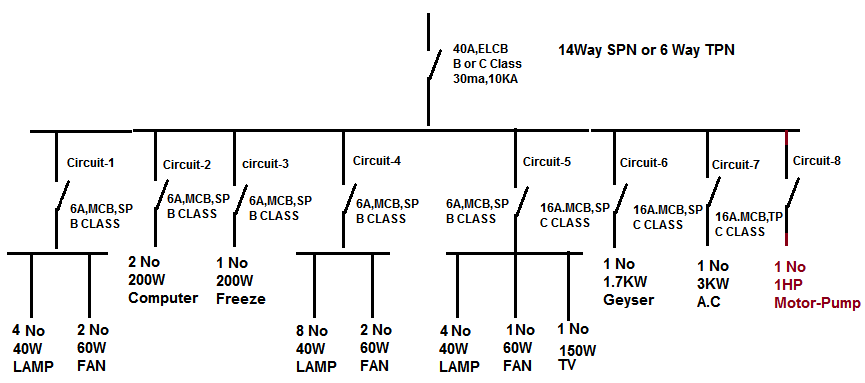
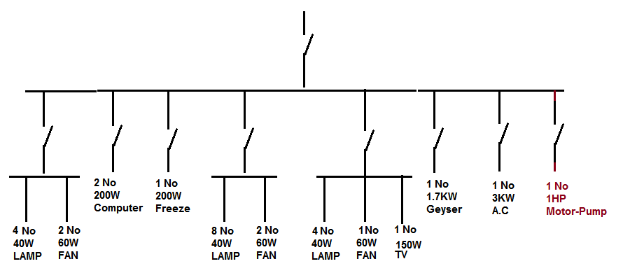
Design Distribution Box of one House and Calculation of Size of Main ELCB and branch Circuit MCB as following Load Detail. Power Supply is 430V (P-P), 230 (P-N), 50Hz. Consider Demand Factor 0.6 for Non Continuous Load & 1 for Continuous Load for Each Equipment.

  • Branch Circuit-1: 4 No of 1Phase, 40W, Lamp of Non Continues Load + 2 No’s of 1Ph, 60W, Fan of Non Continues Load. * Branch Circuit-2: 2 No of 1Ph, 200W, Computer of Non Continues Load. * Branch Circuit-3: 1 No of 1Ph, 200W, Freeze of Continues Load. * Branch Circuit-4: 8 No of 1Ph, 40W, Lamp of Non Continues Load + 2 No’s of 1Ph 60W, Fan of Non Continues Load. * Branch Circuit-5: 4 No of 1Ph , 40W, Lamp of Non Continues Load + 1 No’s of 1Ph 60W, Fan of Non Continues Load.+ 1 No’s of 1Ph 150W, TV of Continues Load * Branch Circuit-6: 1 No of 1P , 1.7KW, Geyser of Non Continues Load. * Branch Circuit-7: 1 No of 1Ph, 3KW, A.C of Non Continues Load. * Branch Circuit-8: 1 No of 3Ph, 1HP, Motor-Pump of Non Continues Load.

Untitled

Fault Current Voltage Fault Current 230V 6KA 430V 10KA 11KV 25KA

Class of MCB/ELCB/RCCB Type of Load Class Sensitivity Lighting B Class I∆n:30ma Heater B Class I∆n:30ma Drive C Class I∆n:100ma A.C C Class I∆n:30ma Motor C Class I∆n:100ma Ballast C Class I∆n:30ma Induction Load C Class I∆n:100ma Transformer D Class I∆n:100ma

Size of MCB/ELCB Current (Amp) Lighting Load MCB/ELCB (Amp) Heating/Cooling/Motor-Pump Load MCB/ELCB (Amp) 1.0 to 4.0 6 16 6.0 10 16 10.0 16 16 16.0 20 20 20.0 25 25 25.0 32 32 32.0 40 40 40.0 45 45 45.0 50 50 50.0 63 63 63.0 80 80 80.0 100 100 100.0 125 125 125.0 225 225 225.0 600 600 600.0 800 800 800.0 1600 1600 1600.0 2000 2000 2000.0 3000 3000 3000.0 3200 3200 3200.0 4000 4000 4000.0 5000 5000 5000.0 6000 6000 6000.0 6000 6000

CALCULATION:

SIZE OF MCB FOR BRANCH CIRCUIT-1:

  • Load Current of Lamp= (No X Watt X Demand Factor)/Volt =(4X40X0.6)/230=0.40Amp * Load Current of Fan= (No X Watt X Demand Factor)/Volt =(2X60X0.6)/230=0.31Amp * Branch Circuit-1 Current as per NEC = Non Continues Load+125% Continues Load * Branch Circuit-1 Current as per NEC =(0.4+0.31)+125%(0) =0.73Amp * Type of Load=Lighting Type * Class of MCB=B Class * Size of MCB=6 Amp * No of Pole of MCB=Single Pole

SIZE OF MCB FOR BRANCH CIRCUIT-2:

  • Load Current of Computer = (No X Watt X Demand Factor)/Volt =(2X200X0.6)/230=1.04Amp * Branch Circuit-2 Current as per NEC = Non Continues Load+125% Continues Load * Branch Circuit-2 Current as per NEC =(1.04)+125%(0) =1.04Amp * Type of Load=Lighting Type * Class of MCB=B Class * Size of MCB=6 Amp * Breaking Capacity: 6KA * No of Pole of MCB=Single Pole

SIZE OF MCB FOR BRANCH CIRCUIT-3:

  • Load Current of Freeze= (No X Watt X Demand Factor)/Volt =(1X200X0.6)/230=0.87Amp * Branch Circuit-3 Current as per NEC = Non Continues Load+125% Continues Load * Branch Circuit-3 Current as per NEC =(0.87)+125%(0) =0.87Amp * Type of Load=Lighting Type * Class of MCB=B Class * Size of MCB=6 Amp * Breaking Capacity: 6KA * No of Pole of MCB=Single Pole

SIZE OF MCB FOR BRANCH CIRCUIT-4:

  • Load Current of Lamp= (No X Watt X Demand Factor)/Volt =(8X40X0.6)/230=0.83Amp * Load Current of Fan= (No X Watt X Demand Factor)/Volt =(2X60X0.6)/230=0.31Amp * Branch Circuit-4 Current as per NEC = Non Continues Load+125% Continues Load * Branch Circuit-4 Current as per NEC =(0.83+0.31)+125%(0) =1.15Amp * Type of Load=Lighting Type * Class of MCB=B Class * Size of MCB=6 Amp * Breaking Capacity: 6KA * No of Pole of MCB=Single Pole

SIZE OF MCB FOR BRANCH CIRCUIT-5:

  • Load Current of Lamp= (No X Watt X Demand Factor)/Volt =(4X40X0.6)/230=0.42Amp * Load Current of Fan= (No X Watt X Demand Factor)/Volt =(1X60X0.6)/230=0.16Amp * Load Current of TV = (No X Watt X Demand Factor)/Volt =(1X150X1)/230=0.65Amp * Branch Circuit-5 Current as per NEC = Non Continues Load+125% Continues Load * Branch Circuit-5 Current as per NEC =(0.42+0.16)+125%(0.65) =0.57+0.82=1.39Amp * Type of Load=Lighting Type * Class of MCB=B Class * Size of MCB=6 Amp * Breaking Capacity: 6KA * No of Pole of MCB=Single Pole

SIZE OF MCB FOR BRANCH CIRCUIT-6:

  • Load Current of Geyser= (No X Watt X Demand Factor)/Volt =(1X1700X0.6)/230=4.43Amp * Branch Circuit-6 Current as per NEC = Non Continues Load+125% Continues Load * Branch Circuit-6 Current as per NEC =(4.43)+125%(0) =4.43Amp * Type of Load=Heating & Cooling Type * Class of MCB=C Class * Size of MCB=16 Amp * Breaking Capacity: 6KA * No of Pole of MCB=Single Pole

SIZE OF MCB FOR BRANCH CIRCUIT-7:

  • Load Current of A.C= (No X Watt X Demand Factor)/Volt =(1X3000X0.6)/230=7.83Amp * Branch Circuit-7 Current as per NEC = Non Continues Load+125% Continues Load * Branch Circuit-7 Current as per NEC =(7.83)+125%(0) =7.83Amp * Type of Load=Heating & Cooling Type…
(2) PANEL / BUS BAR / RELAY:

6. Calculate Weight of Electrical Panel

CALCULATE WEIGHT OF ELECTRICAL PANEL

EXAMPLE-1 (SINGLE COMPARTMENT PANEL):

  • Calculate Electrical Panel Weight having height of 800mm, width of 200mm and depth of 500mm. * The panel material is CRCA steel having 2mm thickness. CRCA Steel density is 7860 kg/m3. * Panel is Mounted on MS Angle Stand of 25x25x4.5 mm, Height of Stand is 500mm, Weight of MS Angle is 1.6Kg/Meter

1

CALCULATION:

  • We need to calculate Weight of CRCA Steel Sheet for Front, Top and Side of Panel.

FRONT SIDE (FRONT + BACK):

  • From Front side We can see either 3 no’s of Plate (Front, Back and Switchgear Mounting Plate) or 2 no’s of Plate (Front and Back) according to Type of Panel. * Front & Back Side Steel Sheet Weight = Height X Width X Density of Sheet X Thickness of Sheet X No of Sheet * Front & Back Side Steel Sheet Weight =0.8 x 0.5 x 7860 x 0.002 x 3 * Front & Back Side Steel Sheet Weight =18.86 Kg

TOP SIDE (TOP + BOTTOM):

  • Top Side Steel Sheet Weight = Height X Depth X Density of Sheet X Thickness of Sheet X No of Sheet * Top Side Steel Sheet Weight =0.2 x 0.5 x 7860 x 0.002 x 2 * Top Side Steel Sheet Weight =3.14 Kg

SIDE (LEFT + RIGHT):

  • Side Steel Sheet Weight = Height X Depth X Density of Sheet X Thickness of Sheet X No of Sheet * Side Steel Sheet Weight =0.8 x 0.2 x 7860 x 0.002 x 2 * Side Steel Sheet Weight = 5.03 Kg

PANEL MS STAND WEIGHT.

  • Total Peripheral Length of Panel = 500+500+200+200=1400 =1.4 Meter * Height of Stand is 500mm, Length of MS Angle =500×4=2000=2 Meter * Total Length of 25x25x4.5 mm MS Angle =1.4+2=3.4 Meter * Weight of 25x25x4.5 mm MS Angle is 1.6 Kg/Meter * Total 75MM MS Base channel Weight =3.4 x 1.6 = 5.44 Kg

TOTAL PANEL WEIGHT

  • Total Electrical Panel Weight = Front Sheet Weight + Top Sheet Weight + Side Sheet Weight+ MS Stand * Total Electrical Panel Weight = 18.86 +314 + 5.03 + 5.44 = 32.47 Kg * Considering extra 20% weight for Hinges, Lock etc. * Total Electrical Panel Weight =32.47 x 1.2 =38.97 Kg

TOTAL ELECTRICAL PANEL WEIGHT =38.97 KG

EXAMPLE-2 (MULTI COMPARTMENT PANEL):

  • Calculate Electrical Panel Weight having height of 2300mm, width of 3700mm and depth of 500mm. * The panel material is CRCA steel having 2mm thickness. CRCA Steel density is 7860 kg/m3. * The Panel Mounting Base Channel is 75MM.

3

CALCULATION:

  • We need to calculate Weight of CRCA Steel Sheet for Front, Top and Side of Panel for Each Compartment of Panel. * Here Main Size of Compartment is 600mm,300mm and 400mm

(1) FOR 600MM COMPARTMENT:

4

  • FRONT SIDE (FRONT + BACK):

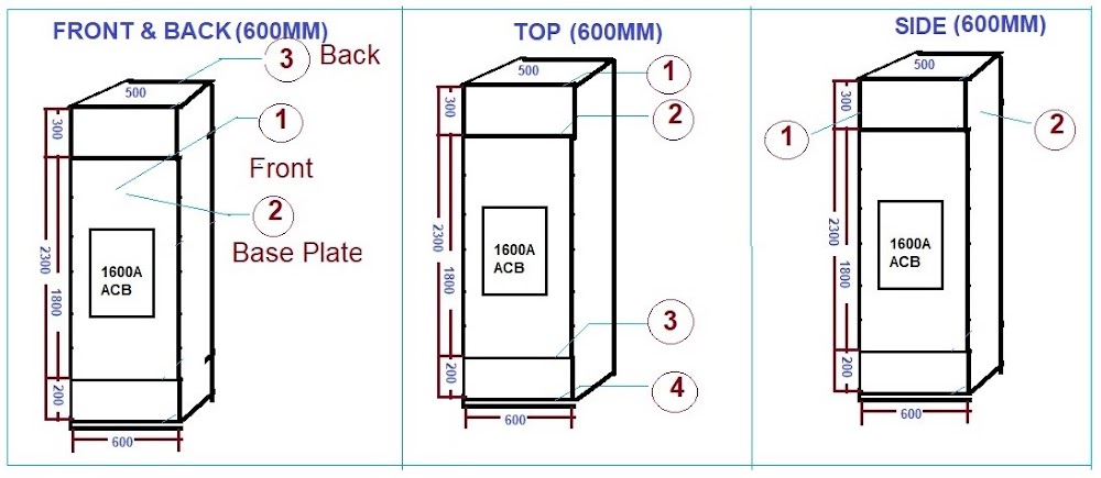
  • From Front side We can see 3 no’s of Plate (Front, Back and Switchgear Mounting Plate). * Total Height=300+1800+200=2300=2.3meter. * Front & Back Side Steel Sheet Weight = Height X Width X Density of Sheet X Thickness of Sheet X No of Sheet * Front & Back Side Steel Sheet Weight =2.3 x 0.6 x 7860 x 0.002 x 3 * Front & Back Side Steel Sheet Weight =65.08 Kg————————–(1)

  • TOP SIDE (TOP + BOTTOM):

  • Top Side Steel Sheet Weight = Height X Depth X Density of Sheet X Thickness of Sheet X No of Sheet * Top Side Steel Sheet Weight =0.6 x 0.5 x 7860 x 0.002 x 4 * Top Side Steel Sheet Weight =18.86 Kg——————————–(2)

  • SIDE (LEFT + RIGHT):

  • Side Steel Sheet Weight = Height X Depth X Density of Sheet X Thickness of Sheet X No of Sheet * Side Steel Sheet Weight =2.3 x 0.5 x 7860 x 0.002 x 2 * Side Steel Sheet Weight = 36.15 Kg————————————–(3)

  • TOTAL 600MM COMPARTMENT WEIGHT:

  • 600MM Compartment Weight= (1) + (2) + (3) =65.08+18.86+36.15=120.1Kg * No of 600MM Compartment in Panel=1 No * TOTAL 600MM Compartment Weight =120.1×1=120.1 Kg———(A)

(2) FOR 300MM COMPARTMENT:

5

  • FRONT SIDE (FRONT + BACK):

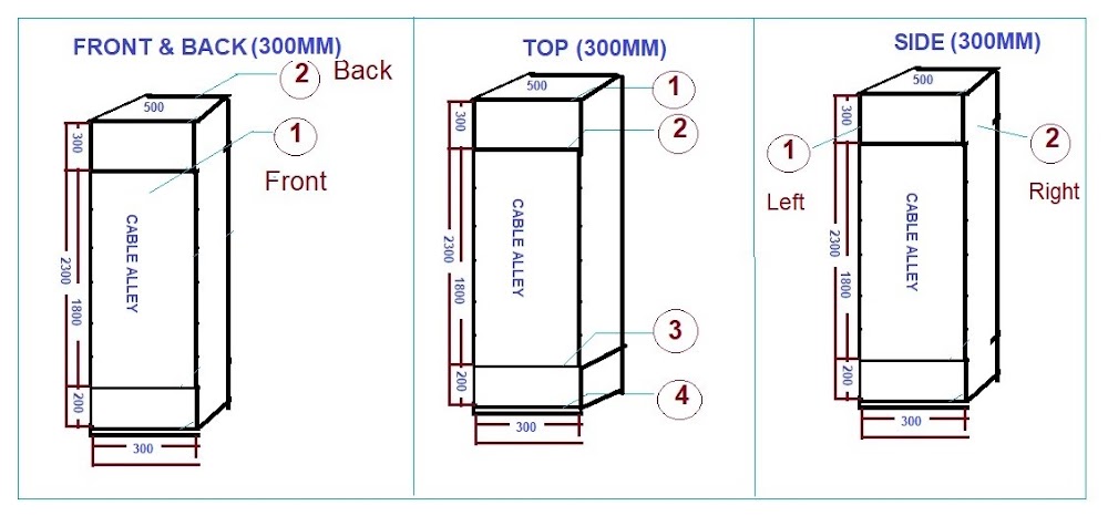
  • From Front side We can see 2 no’s of Plate (Front and Back, In Busbar Chamber Base plate is not required). * Total Height=300+1800+200=2300=2.3meter. * Front & Back Side Steel Sheet Weight = Height X Width X Density of Sheet X Thickness of Sheet X No of Sheet * Front & Back Side Steel Sheet Weight =2.3 x 0.3 x 7860 x 0.002 x 2 * Front & Back Side Steel Sheet Weight =21.69 Kg————————–(1)

  • TOP SIDE (TOP + BOTTOM):

  • Top Side Steel Sheet Weight = Height X Depth X Density of Sheet X Thickness of Sheet X No of Sheet * Top Side Steel Sheet Weight =0.3 x 0.5 x 7860 x 0.002 x 4 * Top Side Steel Sheet Weight =9.43 Kg——————————–(2)

  • SIDE (LEFT + RIGHT):

  • Side Steel Sheet Weight = Height X Depth X Density of Sheet X Thickness of Sheet X No of Sheet * Side Steel Sheet Weight =2.3 x 0.5 x 7860 x 0.002 x 1 (We can see 2 No’s of Plate but 1 No of Plate is already considered in adjoin 600MM Compartment) * Side Steel Sheet Weight = 18.07 Kg————————————–(3)

  • TOTAL 300MM COMPARTMENT WEIGHT:

  • 300MM Compartment Weight= (1) + (2) + (3) =21.69+9.43+18.07=49.20Kg * No of 300MM Compartment in Panel=5 No * TOTAL 300MM Compartment Weight =49.20×5=246.01 Kg———(B)

 (4) FOR 400MM COMPARTMENT:

6

  • FRONT SIDE (FRONT + BACK):

  • Fro…

(2) PANEL / BUS BAR / RELAY:

7. Calculate Dimension of Electrical Panel from SLD

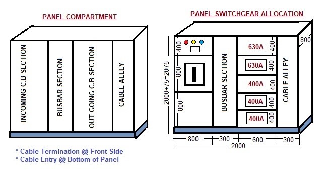
CALCULATE DIMENSION OF ELECTRICAL PANEL FROM SLD

INTRODUCTION:

  • In Designing Stage , We need to calculate approximate Dimension of Electrical Panel to conclude Dimension of Electrical Room and Total Space requirement of Electrical Services. * Dimension of Electrical Panel’s is calculated from Electrical SLD. * Dimension of Electrical Panel mainly depends on
  1. Size of Main Incoming and Outgoing Circuit Barker. 2. No of Outgoing Circuit Breakers. 3. Panel’s Form Factor. 4. Type of Panel (Indoor / Outdoor). 5. Cable connection in Panel (Front Side / Back side of Panel). 6. Installation of Circuit Breaker (Horizontal / Vertical) 7. Height of Panel should not be more than 2200mm Due to Operation of Upmost Switchgear.

GENERAL SWITCHGEAR ARRANGEMENTS IN PANEL 

  • There are four compartments in Electrical Panel.
  1. Incoming Section 2. Outgoing Section 3. Busbar Chamber 4. Cable Alley.

1

FACTORS TO BE CONSIDERED TO CALCULATE DIMENSION OF PANEL:

  • Dimension of Panel mainly depends on following factors.
  1. TYPE OF PANEL (INDOOR / OUTDOOR):
  • Depth of Panel is depending on Type of Panel. * If We have Indoor Type of Panel and there are no any issue regarding Water seepages near Panel than Double Door type of Panel is not required. * In Out Door Type Panel construction is mostly Double Door Type. * For Double Door Construction required more 100mm Panel Depth than actual .

2

  1. FORM FACTOR OF PANEL:
  • Type of Form Factor decide Dimension of Panel. * For Same type and same rating of Switchgear Form 1 required less space compared to Form 2A, 2B, 3A, 3B, 4A, 4B.
  1. POSITION OF SWITCH GEAR INSTALLATION
  • Panel’s Width and Height mostly depends on Position of Switchgear Installation. * If we installed Switchgear in vertical Position than Height of Panel is increased. * If we installed Switchgear in horizontal position than with of Panel is increased. * Most of manufacture prefer Horizontal position of Switchgear to easy termination of Incoming and Outgoing of Switchgear to Busbar.

3

  1. HEIGHT OF PANEL
  • Height of Panel should not more than 2200mm for easy operation of upmost Switchgear in Panel. * This 2200MM height concert increase width of Panel if we have multiple number of outgoing.

  • If we have 5 Nos of outgoing than it may require one No of Colum Section of Panel (400×5=2000mm).

  • But if we have 8 No’s of outgoing than we required two no of Colum Section in one Section 4 no of Outgoing Switchgear and in second Colum section for 3 no of Switch gear. 1 no of More cable alley section (300mm) required for cable termination.

4

  1. CABLE TERMINATION IN PANEL (FRONT SIDE / BACK SIDE)
  • Front Side Cable Termination: If We Installed Panel In front of wall than Panel Back Side is not accessible hence We need Cable Termination on front side of Panel for this we need Cable Alley of 300mm for Cable Termination. * This arrangement increase width of 300mm for panel but depth of panel will not increase. * Back Side Cable Termination: If We Installed Panel at some distance from wall than Panel Back Side is accessible hence, we may do Cable Termination on back side of Panel for this arrangement we need more 300mm depth for Cable Termination. * This arrangement will not increase width of panel but depth of panel will not increase 300mm.

5

GENERAL COMPARTMENT SIZE FOR VARIOUS SWITCHGEAR IN PANEL.

SIZE OF MCB / MCCB COMPARTMENT (CABLE CONNECTIONS ARE IN FRONT OF PANEL)

MCB / MCCB Size

Position

Width (mm)

Height (mm)

Depth (mm)

Up to 63A

Horizontal

300

275

300

63A to 100A

Horizontal

350

300

300

125A to 250A

Horizontal

350 to 400

300 to 350

300 to 350

400A to 630A

Horizontal

600

400

350 to 400

MCCB 800A

Horizontal

600

600

700

MCCB 1250A to 3200A

Horizontal

800

850

1000

  • Cable Connections are in front side of Panel, If Cable Connection are in Back Side of Panel add 300mm in Depth of Panel

  • Cable Termination Space in Panel (From Cable Entry at Panel to Termination Location) Up to 800A =more than 400 mm, above 800A It should be more than 800mm.

SIZE OF ACB COMPARTMENT (CABLE CONNECTIONS ARE IN FRONT OF PANEL)

ACB Size

Position

Width (mm)

Height (mm)

Depth (mm)

800A

Horizontal

700

800

800

1600A

Horizontal

800

800

850

ACB up to 3200A

Horizontal

800

850

1000

ACB Above 3200A

Horizontal

1400

1000

1200

For Cable Entry from Bottom of Panel=Min 700mm Height from Bottom to Cable Termination

  • Cable Termination Space in Panel (From Cable Entry at Panel to Termination Location) Up to 800A =more than 400 mm, Above 800A It should be more than 800mm.

SIZE OF SFU COMPARTMENT (CABLE CONNECTIONS ARE IN FRONT OF PANEL)

SFU Size

Position

Width (mm)

Height (mm)

Depth (mm)

125A

Horizontal

400

350

300

200A

Horizontal

400

350

300

200A

Horizontal

400

400

300

  • Cable Connections are in front side of Panel , If Cable Connection are in Ba…

1. Calculate Size of Circuit Breaker/ Fuse for Transformer (As per NEC)

CALCULATE SIZE OF CIRCUIT BREAKER/ FUSE FOR TRANSFORMER (AS PER NEC)

  • Calculate Size of Circuit Breaker or Fuse on Primary and Secondary side of Transformer having following Detail * Transformer Details(P)= 1000KVA * Primary Voltage (Vp)= 11000 Volt * Secondary Voltage (Vs)= 430 Volt * Transformer Impedance= 5% * Transformer Connection = Delta / Star * Transformer is in unsupervised condition.

CALCULATIONS:

  • Transformer Primary Current (Ip)= P/1.732xVp * Transformer Primary Current (Ip)=1000000/1.732×11000=49Amp * Transformer Secondary Current (Is)= P/1.732xVs * Transformer Secondary Current (Is)=1000000/1.732×430=71Amp * AS per NEC 450.3, Max.Rating of C.B or Fuse is following % of its Current according to it’s Primary Voltage,% Impedance and Supervised/Unsupervised Condition.

Max Rating of Over current Protection for Unsupervised Transformer More than 600 Volts (As per NEC)

%Imp Primary secondary >600Volt >600Volt <600Volt C.B Fuse C.B Fuse C.B/Fuse Up to 6% 600% 300% 300% 250% 125% More than 6% 400% 300% 250% 225% 125%

Max Rating of Over current Protection for Supervised Transformer More than 600 Volts (As per NEC)

%Imp Primary secondary >600Volt >600Volt <600Volt C.B Fuse C.B Fuse C.B/Fuse Up to 6% 600% 300% 300% 250% 250% More than 6% 400% 300% 250% 225% 250%

Max Rating of Over current Protection for Transformers Primary Voltage Less than 600 Volts (As per NEC)

Protection Primary Protection Secondary Protection Method More than 9A 2A to 9A Less than 2A More than 9A Less than 9A Primary only protection 125% 167% 300% Not required Not required Primary and secondary protection 250% 250% 250% 125% 167%

Size of Fuse / Inverse Time C.B as per NEC (Amp)

1 25 60 125 250 600 2000 3 30 70 150 300 700 2500 6 35 80 160 350 800 3000 10 40 90 175 400 1000 4000 15 45 100 200 450 1200 5000 20 50 110 225 500 1600 6000

For Primary Side:

  • Transformer Primary Current (Ip) =52.49Amp and impedance is 5% * As per above table in not supervised condition Size of Circuit Breaker= 600% of Primary Current * Size of Circuit Breaker = 52.49 x 600% =315Amp * If Transformer is in supervised condition then Select Circuit Breaker near that size but if Transformer is in unsupervised condition then Select Circuit Breaker next higher size. * Rating of Circuit Breaker =350Amp (Next Higher Size of 300Amp) * Size of Fuse = 52.49 x300% =157Amp * Rating of Fuse =160Amp (Next Higher Size of 150Amp)

For Secondary Side:

  • Transformer Secondary Current (Is) =1342.70Amp and impedance is 5% * As per above table in not supervised condition Size of Circuit Breaker= 125% of Secondary Current * Size of Circuit Breaker = 1342.70 x 125% =1678Amp * If Transformer is in supervised condition then Select Circuit Breaker near that size but if Transformer is in unsupervised condition then Select Circuit Breaker next higher size. * Rating of Circuit Breaker =2000Amp (Next Higher Size of 1600Amp) * Size of Fuse = 1342.70 x125% =1678Amp * Rating of Fuse =2000Amp (Next Higher Size of 1600Amp)

 RESULTS:

  • Size of Circuit Breaker on Primary Side=350Amp * Size of Fuse on Primary Side=160Amp * Size of Circuit Breaker on Secondary Side=2000Amp * Size of Fuse on Secondary Side=2000Amp
Cover image
(3) TRANSMISSION / DISTRIBUTION / TRANSFORMER:

2. Calculation Short Circuit Current (Base KVA Method)

SHORT CIRCUIT CURRENT CALCULATION (BASE KVA METHOD)

EXAMPLE:

Calculate Fault current at each stage of following Electrical System SLD having details of.

  • Main Incoming HT Supply Voltage is 6.6 KV. * Fault Level at HT Incoming Power Supply is 360 MVA. * Transformer Rating is 2.5 MVA. * Transformer Impedance is 6%.

Untitled

  • Let’s first consider Base KVA and KV for HT and LT Side. * Base KVA for HT side (H.T. Breaker and Transformer Primary) is 6 MVA * Base KV for HT side (H.T. Breaker and Transformer Primary) is 6.6 KV * Base KVA for LT side (Transformer Secondary and down Stream) is 2.5 MVA * Base KV for LT side (Transformer Secondary and down Stream) is 415V

FAULT LEVEL AT HT SIDE (UP TO SUB-STATION):

(1) FAULT LEVEL FROM HT INCOMING LINE TO HT CIRCUIT BREAKER

  • HT Cable used from HT incoming to HT Circuit Breaker is 5 Runs , 50 Meter ,6.6KV 3 Core 400 sq.mm Aluminum Cable , Resistance of Cable 0.1230 Ω/Km and Reactance of Cable is0.0990 Ω/Km. * Total Cable Resistance(R)= (Length of Cable X Resistance of Cable) / No of Cable. * Total Cable Resistance=(0.05X0.1230) / 5 * Total Cable Resistance=0.001023 Ω * Total Cable Reactance(X)= (Length of Cable X Reactance of Cable) / No of Cable. * Total Cable Reactance=(0.05X0.0990) / 5 * Total Cable Reactance =0.00099 Ω * Total Cable Impedance (Zc1)=√(RXR)+(XxX) * Total Cable Impedance (Zc1)=0.0014235 Ω——–(1) * U Reactance at H.T. Breaker Incoming Terminals (X Pu)= Fault Level / Base KVA * U Reactance at H.T. Breaker Incoming Terminals (X Pu)= 360 / 6 * U. Reactance at H.T. Breaker Incoming Terminals(X Pu)= 0.01666 PU——(2) * Total Impedance up to HT Circuit Breaker (Z Pu-a)= (Zc1)+ (X Pu) =(1)+(2) * Total Impedance up to HT Circuit Breaker(Z Pu-a)=0.001435+0.01666 * Total Impedance up to HT Circuit Breaker (Z Pu-a)=0.0181 Ω.——(3) * Fault MVA at HT Circuit Breaker= Base MVA / Z Pu-a. * Fault MVA at HT Circuit Breaker= 6 / 0.0181 * Fault MVA at HT Circuit Breaker= 332 MVA * Fault Current = Fault MVA / Base KV * Fault Current = 332 / 6.6 * Fault Current at HT Circuit Breaker = 50 KA

(2) FAULT LEVEL FROM HT CIRCUIT BREAKER TO PRIMARY SIDE OF TRANSFORMER

  • HT Cable used from HT Circuit Breaker to Transformer is 3 Runs , 400 Meter ,6.6KV 3 Core 400 sq.mm Aluminium Cable , Resistance of Cable 0.1230 Ω/Km and Reactance of Cable is0.0990 Ω/Km. * Total Cable Resistance(R)= (Length of Cable X Resistance of Cable) / No of Cable. * Total Cable Resistance=(0.4X0.1230) / 3 * Total Cable Resistance=0.01364 Ω * Total Cable Reactance(X)= (Length of Cable X Reactance of Cable) / No of Cable. * Total Cable Reactance=(0.4X0.0990) / 5 * Total Cable Reactance =0.01320 Ω * Total Cable Impedance (Zc2)=√(RXR)+(XxX) * Total Cable Impedance (Zc2)=0.01898 Ω——–(4) * U Impedance at Primary side of Transformer (Z Pu)= (Zc2 X Base KVA) / (Base KV x Base KVx1000) * U Impedance at Primary side of Transformer (Z Pu)= (0.01898X6) /(6.6×6.6×1000) * U Impedance at Primary side of Transformer (Z Pu)= 0.0026145 PU——(5) * Total Impedance(Z Pu)=(4) + (5) * Total Impedance(Z Pu)=0.01898+0.0026145 * Total Impedance(Z Pu)=0.00261——(6) * Total Impedance up to Primary side of Transformer (Z Pu-b)= (Z Pu)+(Z Pu-a) =(6)+(3) * Total Impedance up to Primary side of Transformer (Z Pu-b)= 0.00261+0.0181 * Total Impedance up to Primary side of Transformer (Z Pu-b)=0.02070 Ω.—–(7) * Fault MVA at Primary side of Transformer = Base MVA / Z Pu-b. * Fault MVA at Primary side of Transformer = 6 / 0.02070 * Fault MVA at Primary side of Transformer = 290 MVA * Fault Current = Fault MVA / Base KV * Fault Current = 290 / 6.6 * Fault Current at Primary side of Transformer = 44 KA

(3) FAULT LEVEL FROM PRIMARY SIDE OF TRANSFORMER TO SECONDARY SIDE OF TRANSFORMER:

  • Transformer Rating is 2.5 MVA and Transformer Impedance is 6%. * % Reactance at Base KVA = (Base KVA x % impedance at Rated KVA) / Rated KVA * % Reactance at Base KVA = (2.5X6)/2.5 * % Reactance at Base KVA =6% * U. Reactance of the Transformer(Z Pu) =% Reactance /100 * U. Reactance of the Transformer(Z Pu)= 6/100=0.06 Ω—–(8) * Total P.U. impedance up to Transformer Secondary Winding(Z Pu-c)=(Z Pu)+(Z Pu-b)=(7)+(8) * Total P.U. impedance up to Transformer Secondary Winding(Z Pu-c)=0.06+0.02070 * Total P.U. impedance up to Transformer Secondary Winding(Z Pu-c)=0.0807 Ω—–(9) * Fault MVA at Transformer Secondary Winding = Base MVA / Z Pu-c * Fault MVA at Transformer Secondary Winding = 2.5/0.0807 * Fault MVA at Transformer Secondary Winding =31 MVA * Fault Current = Fault MVA / Base KV * Fault Current = 31 / (1.732×0.415) * Fault Current at Transformer Secondary Winding = 43 KA

FAULT LEVEL AT LT SIDE (SUB-STATION TO DOWN STREAM):

(4) FAULT LEVEL FROM TRANSFORMER SECONDARY TO MAIN LT PANEL

  • LT Cable used from Transformer Secondary to Main LT Panel is 13 Runs , 12 M…

3. Calculate Technical Losses of Transmission / Distribution Line

CALCULATE TECHNICAL LOSSES OF TRANSMISSION / DISTRIBUTION LINE:

INTRODUCTION:

  • There are two types of Losses in transmission and distribution Line. * (1) Technical Losses and * (2) Commercial Losses. * It is necessary to calculate technical and commercial losses.Normally Technical Losses and Commercial Losses are calculated separately .Transmission (Technical) Losses are directly effected on electrical tariff but Commercial losses are not implemented to all consumers. * Technical Losses of the Distribution line mostly depend upon Electrical Load, type and size of conductor, length of line etc. * Let’s try to calculate Technical Losses of one of following 11 KV Distribution Line

EXAMPLE:

  • 11 KV Distribution Line have following parameter. * Main length of 11 KV Line is 6.18 Kms. * Total nos. of Distribution Transformer on Feeder 25 KVA= 3 No, 63 KVA =3 No,100KVA=1No. * 25KVA Transformer Iron Losses = 100 W, Copper Losses= 720 W, Average LT Line Loss= 63W. * 63KVA Transformer Iron Losses = 200 W, Copper Losses= 1300 W, Average LT Line Loss= 260W. * 100KVA Transformer Iron Losses = 290 W, Copper Losses= 1850 W, LT Line Loss= 1380W. * Maximum Amp is12 Amps. * Unit sent out during to feeder is 490335 Kwh * Unit sold out during from Feeder is 353592 Kwh * Normative Load diversity Factor for Urban feeder is 1.5 and for Rural Feeder is 2.0

CALCULATION:

Total Connected Load=No’s of Connected Transformer.

  • Total Connected Load= (25×3) + (63×3) + (100×1). * Total Connected Load=364 KVA.

 Peak Load = 1.732 x Line Voltage x Max Amp

  • Peak Load = 1.732x11x12 * Peak Load =228 KVA.

 Diversity Factor (DF) = Connected Load (In KVA) / Peak Load.

  • Diversity Factor (DF) = 364 /228 * Diversity Factor (DF) =1.15

 Load Factor (LF)= Unit Sent Out (In Kwh) / 1.732 x Line Voltage x Max Amp. x P.F. x 8760

  • Load Factor (LF)=490335 / 1.732x11x12x0.8×8760 * Load Factor (LF)=0.3060

 Loss Load Factor (LLF)= (0.8 x LFx LF)+ (0.2 x LF)

  • Loss Load Factor (LLF)= ( 0.8 x 0.3060 x 0.3060 ) + (0.2 x 0.306) * Loss Load Factor (LLF)= 0.1361

 Calculation of Iron losses:

  • Total Annual Iron loss in Kwh =Iron Loss in Watts X Nos of TC on the feeder X8760 / 1000 * Total Annual Iron loss (25KVA TC)=100x3x8760 /1000 =2628 Kwh * Total Annual Iron loss (63KVA TC)=200x3x8760 /1000 =5256 Kwh * Total Annual Iron loss (100KVA TC)=290x3x8760 /1000 =2540 Kwh * Total Annual Iron loss =2628+5256+2540 =10424Kwh

 Calculation of Copper losses:

  • Total Annual Copper loss in Kwh =Cu Loss in Watts XNos of TC on the feeder LFX LF X8760 / 1000 * Total Annual Copper loss (25KVA TC)=720x3x0.3×0.3×8760 /1000 =1771 Kwh * Total Annual Copper loss (63KVA TC)=1300x3x0.3×0.3×8760 /1000 =3199 Kwh * Total Annual Copper loss (100KVA TC)=1850x1x0.3×0.3×8760 /1000 =1458 Kwh * Total Annual Copper loss =1771+3199+1458=6490Kwh

 HT Line Losses (Kwh)=0.105 x (Conn. Load x 2) x Length x Resistance x LLF /( LDF x DF x DF x 2 )

  • HT Line Losses= 1.05 x(265×2) x 6.18 x 0.54 x 0.1361 /1.5 x 1.15 x1.15 x 2 * HT Line Losses = 831 Kwh

 Peak Power Losses= (3 x Total LT Line Losses) / (PPLxDFxDFx 1000)

  • Peak Power Losses= 3 x (3×63+3×260+1×1380) /1.15 x 1.15 x 1000 * Peak Power Losses= 3.0

 LT Line Losses (Kwh)= (PPL.) x (LLF) x 8760

  • LT Line Losses = 3 x 0.1361 x 8760 * LT Line Losses = 3315 Kwh

 Total Technical Losses= (HT Line Losses + LT Line Losses + Annual Cu Losses + Annual Iron Losses)

  • Total Technical Losses = ( 831+ 3315 + 10424 + 6490) * Total Technical Losses = 21061 Kwh

% Technical Loss= (Total Losses) / (Unit Sent Out Annually) x 100

  • % Technical Loss= (21061/490335) x100= 4.30%

% TECHNICAL LOSS=4.30%

Cover image
(3) TRANSMISSION / DISTRIBUTION / TRANSFORMER:

4. Calculate Voltage Regulation of Distribution Line

CALCULATE VOLTAGE REGULATION OF DISTRIBUTION LINE

INTRODUCTION:

  • Voltage regulation or Load Reguation is to maintain a fixed voltage under different load.Voltage regulation is limiting factor to decide the size of either conductor or type of insulation.

  • In circuit current need to be lower than this in order to keep the voltage drop within permissible values. The high voltage circuit should be carried as far as possible so that the secondary circuit have small voltage drop.

VOLTAGE REGULATION FOR 11KV, 22KV, 33KV OVERHEAD LINE (AS PER REC):

  • % VOLTAGE REGULATION= (1.06XPXLXPF) / (LDFXRCXDF)

  • Where * P=Total Power in KVA * L= Total Length of Line from Power Sending to Power Receiving in KM. * PF= Power Factor in p.u * RC= Regulation Constant (KVA-KM) per 1% drop. * RC=(KVxKVx10)/( RCosΦ+XSinΦ) * LDF= Load Distribution Factor. * LDF= 2 for uniformly distributed Load on Feeder. * LDF>2 If Load is skewed toward the Power Transformer. * LDF= 1 To 2 If Load is skewed toward the Tail end of Feeder. * DF= Diversity Factor in p.u

PERMISSIBLE VOLTAGE REGULATION (AS PER REC):

Maximum Voltage Regulation at any Point of Distribution Line

Part of Distribution System Urban Area (%) Suburban Area (%) Rural Area (%) Up to Transformer 2.5 2.5 2.5 Up to Secondary Main 3 2 0.0 Up to Service Drop 0.5 0.5 0.5 Total 6.0 5.0 3.0

 VOLTAGE REGULATION VALUES:

  • The voltage variations in 33 kV and 11kV feeders should not exceed the following limits at the farthest end under peak load conditions and normal system operation regime. * Above 33kV (-) 12.5% to (+) 10%. * Up to 33kV (-)9.0% to (+)6.0%. * Low voltage (-)6.0% to (+) 6.0% * In case it is difficult to achieve the desired voltage especially in Rural areas, then 11/0.433kV distribution transformers(in place of normal 11/0.4kV DT’s) may be used in these areas.

REQUIRED SIZE OF CAPACITOR:

  • Size of capacitor for improvement of the Power Factor from Cos ø1 to Cos ø2 is

  • REQUIRED SIZE OF CAPACITOR(KVAR) = KVA1 (SIN Ø1 – [COS Ø1 / COS Ø2] X SIN Ø2)

  • Where KVA1 is Original KVA.

OPTIMUM LOCATION OF CAPACITORS:

  • L = [1 – (KVARC / 2 KVARL) X (2N-1)]

  • Where, * L = distance in per unit along the line from sub-station. * KVARC = Size of capacitor bank * KVARL = KVAR loading of line * n = relative position of capacitor bank along the feeder from sub-station if the total capacitance is to be divided into more than one Bank along the line. If all capacitance is put in one Bank than values of n=1.

VOLTAGE RISE DUE TO CAPACITOR INSTALLATION:

  • % VOLTAGE RISE = (KVAR(CAP)X LX X) / 10XVX2

  • Where, * KVAR(Cap)=Capacitor KVAR * X = Reactance per phase * L=Length of Line (mile) * V = Phase to phase voltage in kilovolts 

CALCULATE % VOLTAGE REGULATION OF DISTRIBUTION LINE :

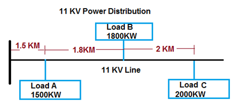
  • Calculate Voltage drop and % Voltage Regulation at Trail end of following 11 KV Distribution system , System have ACSR DOG Conductor (AI 6/4.72, GI7/1.57),Current Capacity of ACSR Conductor =205Amp,Resistance =0.2792Ω and Reactance =0 Ω, Permissible limit of % Voltage Regulation at Trail end is 5%.

Untitled

METHOD-1 (DISTANCE BASE):

  • VOLTAGE DROP = ( (√3X(RCOSΦ+XSINΦ)X I ) / (NO OF CONDUCTOR/PHASE X1000))X LENGTH OF LINE

Voltage drop at Load A

  • Load Current at Point A (I) = KW / 1.732xVoltxP.F * Load Current at Point A (I) =1500 / 1.732x11000x0.8 = 98 Amp. * Required No of conductor / Phase =98 / 205 =0.47 Amp =1 No * Voltage Drop at Point A = ( (√3x(RCosΦ+XSinΦ)xI ) / (No of Conductor/Phase x1000))x Length of Line * Voltage Drop at Point A =((1.732x (0.272×0.8+0x0.6)x98) / 1×1000)x1500) = 57 Volt * Receiving end Voltage at Point A = Sending end Volt-Voltage Drop= (1100-57) = 10943 Volt. * % Voltage Regulation at Point A = ((Sending end Volt-Receiving end Volt) / Receiving end Volt) x100 * % Voltage Regulation at Point A = ((11000-10943) / 10943 )x100 = 0.52% * % Voltage Regulation at Point A =0.52 %

Voltage drop at Load B

  • Load Current at Point B (I) = KW / 1.732xVoltxP.F * Load Current at Point B (I) =1800 / 1.732x11000x0.8 = 118 Amp. * Distance from source= 1500+1800=3300 Meter. * Voltage Drop at Point B = ( (√3x(RCosΦ+XSinΦ)xI ) / (No of Conductor/Phase x1000))x Length of Line * Voltage Drop at Point B =((1.732x (0.272×0.8+0x0.6)x98) / 1×1000)x3300) = 266 Volt * Receiving end Voltage at Point B = Sending end Volt-Voltage Drop= (1100-266) = 10734 Volt. * % Voltage Regulation at Point B= ((Sending end Volt-Receiving end Volt) / Receiving end Volt) x100 * % Voltage Regulation at Point B= ((11000-10734) / 10734 )x100 = 2.48% * % Voltage Regulation at Point B =2.48 %

Voltage drop at Load C

  • Load Current at Point C (I) = KW / 1.732xVoltxP.F * Load Current at Point C (I) =2000 / 1.732x11000x0.8 = 131 Amp * Distance from source= 1500+1800+2000=5300 Meter. * Voltage Drop at Point C = ( (√3x(RCosΦ+XSi…

5. Calculate Transformer Regulation & Losses (As per Transformer Name Plate)

CALCULATE TRANSFORMER REGULATION & LOSSES (AS PER TRANSFORMER NAME PLATE)

Calculate Transformer Regulation and Losses for following Transformer Name Plate Details

  • KVA rating of Transformer(P)=16000VA * Primary voltage(Vp)=11000V * Secondary voltage(Vs)=433V * No load losses(W0)=72Watt * No load current(I0)=0.59Amp * Full load losses(W)=394Watt * Impedance voltage(Vi)=480Volt * LV resistance(Rs) =219.16 miliΩ * HV resistance(Rp) =215.33 Ω * Amb temperature(c)=30 Deg C * Total Connected Load on Transformer(Pl)=10000VA

Calculation:

  • % Loading of Transformer=Pl/P * % Loading of Transformer=10000/16000 = 63%

I2R Calculation:

  • HV Full load current (Ip) =P/Vpx1.732 * HV Full load current (Ip) =16000/11000×1.732=0.84 Amp * LV Full load current (Is)=P/Vsx1.732 * LV Full load current (Is)==16000/433×1.732=21.33 Amp * HV Side I2R losses= IpxIpxRp * HV Side I2R losses= 0.84×0.84×215.33=227.8 Watt—–(A) * LV Side I2R losses= IsxIsxRs * LV Side I2R losses==21.33×21.33×219.16=149.63 Watt—(B) * Total I² R losses @ Amb temp(Ir)=A+B * Total I² R losses @ Amb temp(Ir)=227.8+149.63=377.43 Watt * Total Stray losses @ Amb temp (Ws) =Full Load Losses-I2R Losses * Total Stray losses @ Amb temp (Ws) =394-377.43=16.57 Watt * I² R losses @75° c temp =Irx310/235xc =149.63×310/235×30 =441.52Watt * Stray loses @ 75° c temp =(Wsx(235+c))/310 * Stray loses @ 75° c temp =(16.57x(235+30))/310=14.16 Watt * Total Full load losses at @75° c=441.52+14.16=455.69 Watt * Total Impedance at ambient temp (Ax)=Vix1.732/Ip * Total Impedance at ambient temp(Ax)=480×1.732/0.84=989.94Ω * Total Resistance at amb temp (Ar)=Ir/IpxIp * Total Resistance at amb temp (Ar)=377.43/0.84×0.84=535.15Ω * Total Reactance (X)=√AxxAx+ArxAr * Total Reactance (X)=√989.98×989.94+535.15×535.15=832.82Ω * Resistance at@ 75° c (R)= (310xAr)/(235+c)=310×535.15/235+30 = 626.03Ω * Impedance at 75° c (X1)=√2X+2R=√2×626.03+2×832.82 = 1041.88Ω * Percentage Impedance = (X1x0.5774xIpx100)/Vp * Percentage Impedance = (1041.88×0.5774×0.84×100)/11000=4.59% * Percentage Resistance (R%) =(Rx0.5774xIpx100)/Vp * Percentage Resistance(R%) =(626.03×0.5774×0.84×100)/11000=2.76% * Percentage Reactance(X%) = (Xx0.5774xIpx100)/Vp * Percentage Reactance(X%) = (832.82 x0.5774×0.84×100)/11000=3.67%

Regulation

  • Regulation at Unity P.F =2.76 * Regulation at Unity at 0.8 P.F =((R% x cosØ)+(X% x SinØ))+(0.005x((R% x SinØ)+(X% x CosØ))) * Regulation at Unity at 0.8 P.F =((2.76 x 0.8)+(3.67 x 0.6))+(0.005x((2.76 x0.6)+(3.67 x 0.8)))=4.43

Results

  • Total I² R losses @ Amb. temp(Ir)= 377.43Watt * Total Stray losses @ Amb. temp (Ws) =16.57 Watt * Regulation at Unity P.F =2.76 * Regulation at Unity at 0.8 P.F =4.43

6. Calculate Size of Transformer & Voltage Drop due to Starting of Multiple No of Motors

CALCULATE SIZE OF TRANSFORMER & VOLTAGE DROP DUE TO STARTING OF MULTIPLE NO OF MOTORS

Calculate Voltage drop in Transformer, 1000KVA, 11/0.480KV, impedance 5.75%, due to starting of 300KW Three Phase Motor and 5KW Single Phase Motor, 460V (Line-Line), 0.8 Power Factor, Locked Rotor Current is 450% and The allowable Voltage drop at Transformer Secondary terminal is 10%.

MOTOR CURRENT / TORQUE:

• Motor Full Load Current= (Kwx1000)/(1.732x Volt (L-L)x P.F) • Motor Full Load Current=300×1000/1.732x460x0.8= 471 Amp. • Motor Full Load Current= (Kwx1000)/( Volt (L-P)x P.F) • Motor Full Load Current=10×1000/ (460/1.732)x0.8= 24 Amp. • Total Motor Full Load Current=471+24=494 Amp • Motor inrush Kva at Starting (Irsm)=Volt x locked Rotor Current x Full Load Currentx1.732 / 1000 • Motor inrush Kva at Starting (Irsm)=460 x 2118x494x1.732 / 1000=1772 Kva

TRANSFORMER:

• Transformer Full Load Current= Kva/(1.732xVolt) • Transformer Full Load Current=1000/(1.732×480)=1203 Amp. • Short Circuit Current at TC Secondary (Isc) =Transformer Full Load Current / Impedance. • Short Circuit Current at TC Secondary= 1203/5.75= 20919 Amp • Maximum Kva of TC at rated Short Circuit Current (Q1) = (Volt x Iscx1.732)/1000. • Maximum Kva of TC at rated Short Circuit Current (Q1) =480x20919x1.732/1000= 17391 Kva. • Voltage Drop at Transformer secondary due to Motor Inrush (Vd)= (Irsm) / Q1 • Voltage Drop at Transformer secondary due to Motor Inrush (Vd) =1772/17391 =10.2% • Motor Full Load Current<=65% of Transformer Full Load Current • 494 Amp <=65%x1203 amp = 471 Amp<= 781 Amp • Here Motor Full Load Current<=TC Full Load Current but Voltage Drop is High (10.20%) so Size of Transformer is Not Adequate.

REQUIRED TO INCREASE THE SIZE OF TRANSFORMER.

Cover image
(3) TRANSMISSION / DISTRIBUTION / TRANSFORMER:

7. Calculate Short Circuit Current at Sub Panel (End user side)

CALCULATE SHORT CIRCUIT CURRENT AT SUB PANEL (END USER SIDE)

EXAMPLE:

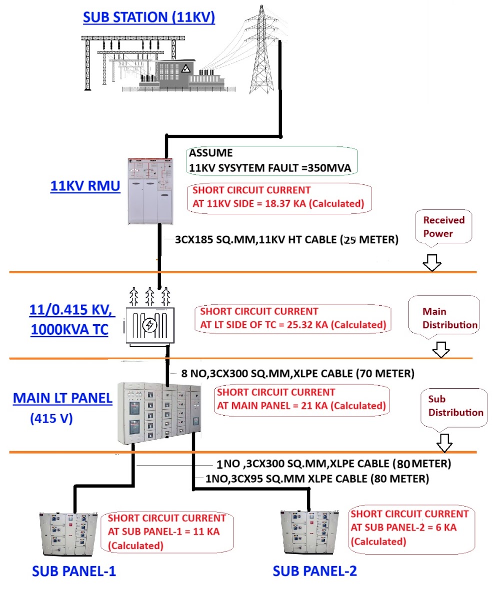
  • Calculate short circuit current at Electrical Equipment Panel / Distribution Board at end user side. * HT Power is received by 11KV RMU and given to 11/0.415KV,1000KVA Transformer by 1 no of 3Cx185 Sq.mm 11KV HT Cable of 25 Meter Length. * Resistance and Reactance of HT cable are 0.21 Ώ / KM and 0.1 Ώ / KM * Transformer impedance is 6.25%. * LT Side of Transformer is connected to Main LT Panel by 8 no of 3.5Cx300 Sq.mm cable of 70 Meter. * Resistance and Reactance of 3.5Cx300 Sq.mm, XLPE cable are 0.129 Ώ / KM and 0.071 Ώ / KM. * Main LT Panel is connected to Sub Panel-1 by 1 no of 3.5Cx300 Sq.mm cable of 80 Meter. * Resistance and Reactance of 3.5Cx300 Sq.mm, XLPE cable are 0.129 Ώ / KM and 0.071 Ώ / KM. * Main LT Panel is connected to Sub Panel-2 by 1 no of 3.5Cx95 Sq.mm cable of 80 Meter. * Resistance and Reactance of 3.5Cx95 Sq.mm, XLPE cable are 0.409 Ώ / KM and 0.072 Ώ / KM. * Calculate Short circuit Current at Sub Panel-1 & Sub Panel-2.

1

CALCUALTION

  • Short Circuit Current is calculated at various points of Power Distribution Networks, At Power Receiving Point (11KV), At Main Panel Point (0.415V) and At Sub Distribution Point (0.415V)

(1) SHORT CIRCUIT CURRENT AT 11 KV PANEL / RMU:

  • Assume that 11KV Side System Fault MVA is 350 MVA. * Shor Circuit Current at 11KV System = Fault MVA / 1.732 x System Voltage at Fault Point. * Shor Circuit Current at 11KV System = 350 / 1.732 x 11. * Shor Circuit Current at 11KV System = 18.37 KA.

 (2) SHORT CIRCUIT CURRENT AT TRANSFORMER:

  • To calculate Short Circuit Current at Transformer Side, First We need to sum Impedance of the system up to Transformer (Impedance of HT Source +Impedance of HT Cable + Impedance of Transformer). * Transformer Capacity is 1000 KVA * Base MVA = TC Size / 1000 * Base MVA = 1000 / 1000 * Base MVA = 1 MVA or * Base KVA = 1000 KVA * % Impedance of Source = Base MVA x100 / System Fault MVA * % Impedance of Source = 1 x100 / 350 * % Impedance of Source = 0.29 Ώ / KM. * CALCULATE % RESISTANCE & REACTANCE OF CABLE ( 185 SQ.MM HT CABLE) * % Resistance of Cable =Base KVA (TC Capacity) x Cable Resistance x No of Run x Length of Cable / (System Voltage in KV)²x10. * % Resistance of Cable =1000 x 0.21 x 1 x 25 / 11x11x10 * % Resistance of Cable =0.004339 % Ώ * % Reactance of Cable =Base KVA (TC Capacity) x Cable Reactance x No of Run x Length of Cable / (System Voltage in KV)²x10. * % Reactance of Cable =1000 x 0.1 x 1 x 25 / 11x11x10 * % Reactance of Cable =0.002066 % Ώ * % Impedance of Cable =√ R² + X² * % Impedance of Cable =√ (0.004339) ² + (0.002066) ² * % Impedance of Cable =0.00481 % Ώ. * Considering 10% Tolerance in Transformer Impedance * % Impedance of Transformer = Impedance of Transformer – 10% Variation of Transformer Impedance * % Impedance of Transformer = 6.25 -(6.25X10%) * % Impedance of Transformer =5.63 % Ώ. * Total % Impedance up to Transformer = % Impedance of Source +%Cable Impedance + % Transformer Impedance * Total % Impedance up to Transformer = 0.29+0.00481+5.63 % Ώ. * Total % Impedance up to Transformer = 5.92% Ώ. * Fault KVA on LT Side of Transformer = Base MVA of Transformer x100 / Total % Impedance up to Transformer. * Fault KVA on LT Side of Transformer = 1 x100 / 5.92. * Fault KVA on LT Side of Transformer = 16.9 KVA. * Short Circuit Current at Transformer LT Side= Fault KVA / 1.732 x System Voltage at Fault Point. * Short Circuit Current at Transformer LT Side= 16.9 / 1.732 x 0.415 * Short Circuit Current at Transformer LT Side= 25.32 KA

 (3) SHORT CIRCUIT CURRENT AT MAIN LT PANEL:

  • To calculate Short Circuit Current at Main LT Panel, we need to sum Impedance of the system up to Main LT Panel (Total Impedance up to Transformer LT Side + Impedance of LT Cable). * Total % Impedance up to Transformer LT Side= 5.92% Ώ. * CALCULATE % RESISTANCE & REACTANCE OF CABLE (300 SQ.MM) * % Resistance of Cable =Base KVA (TC Capacity) x Cable Resistance x Length of Cable / (System Voltage in KV)²x10. * % Resistance of Cable =1000 x 0.129 x 1 x 70 / 0.415 x 0.415 x10 * % Resistance of Cable =0.66 % Ώ * % Reactance of Cable =Base KVA (TC Capacity) x Cable Reactance x No of Run x Length of Cable / (System Voltage in KV)² x10. * % Reactance of Cable =1000 x 0.071 x 8 x 70 / 0.415×0.415×10 * % Reactance of Cable =0.36 % Ώ * % Impedance of Cable =√ R² + X² * % Impedance of Cable =√ (0.66) ² + (0.36) ² * % Impedance of Cable =0.747 % Ώ.——————————–(B) * Total % Impedance up to Main LT Panel = % Impedance up Transformer +%Cable Impedance * Total % Impedance up to Main LT Panel = = 5.92+0.747 % Ώ. * Total % Impedance up to Main LT Panel = = 6.662% Ώ. ————————–(B) * Fault KVA on Main LT Panel= Base MVA x100 / Total % Impedance. * Fault KVA on LT Side of Transformer = 1 x100 / 6.662. * Fault KVA on LT Side of Transformer = 15.01 KVA. * Short Circuit Cur…