Site logo
Electrical Engineering Academy

Quick Reference-Fire Fighting (Part-1)

QUICK REFERENCE-FIRE FIGHTING (PART-1)

September 15, 2019 1 Comment

Class of Fire

CLASS Type of Fire Type of Fire Extinguisher Class A Fires involving Paper, Wood, Textile, Packing materials and the like. Water, foam, ABC dry power and halocarbons. Class B Fires involving Oil, Petrol, Solvent, Grease, Paints, Celluloid and the like. Foam, dry powder, clean agent and carbon dioxide extinguishers Class C Fires involving Electrical Hazards, Motor Vehicle Gaseous substance under pressure. Dry powder, clean agent and carbon dioxide extinguishers Class D Fires involving Chemicals, Metal and active like

Magnesium ,titanium

Extinguishers with special dry powder for metal tires

Area covered by Fire Extinguisher (NBC)

Type of Fire Extinguishers Coverage (Floor) Area Water/ Sand Bucket 100 sq.mt. Sprinklers 6 sq.mt. Extinguishers (9 Liter) 600 sq.mt. Heat Detectors 16 sq.mt. Hydrant Riser (Outlet 100 mm dia with landing valve and First aid hose reel) 930 sq.mt Smoke Detectors 50 sq.mt.

Water Requirement for the Fire Fighting (AS per NBC)

Q = 3000 P Q = Fire demand in Liters/Minutes P = Population in Thousands Note: The above rate must be maintained at a minimum pressure of 1 to 1.5 kg / cm2 for at least four hours.

Water Requirement for Wet Riser/Down Corner System (As per NBC -TABLE 4)

Residential Buildings U.G. Water Storage Tank Static Terrace Tank 15 m to 30 m 50,000 lts 10,000 lts 30 m to 45 m 1,00,000 lts 20,000 lts Above 45 m 2,00,000 lts 40,000 lts

Water Requirement for Wet Riser/Down Corner System (As per NBC -TABLE 5)

Business Building U.G. Water Storage Tank Static Terrace Tank 15 m to 30 m 100000 lts (50000 lts if covered area in G.F is less than 300sq.m.) 20,000 lts 30 m to 45 m 20000 lts 20,000 lts Above 45 m 250000 lts 50,000 lts

Classification of fire Pumps (As per IS 15301)

Pump Size Location of Pump Installation 450 Liter/Min Pumps to be installed on the terrace to feed the Down Comer System. 900 Liter/Min Pumps to be installed on the terrace to feed the Down Comer System. 2280 Liter/Min Pumps are to be housed in the pump house. 2850 Liter/Min Pumps are to be housed in the pump house. 4500 Liter/Min Pumps are to be housed in the pump house. For special risks 6700 Liter/Min Pumps are to be housed in the pump house.

Suction and Delivery Pipe Sizes (IS 3844)

Pump Size Pump Location Suction Delivery 450 Liter/min Terrace 50 mm 50 mm 900 Liter/min Terrace 75 mm 50 mm 1400 Liter/min Terrace 100 mm 100 mm 2280 Liter/min Fire Pump 150 mm 150 mm 2850 Liter/min Fire Pump 200 mm 150 mm 4500 Liter/min Fire Pump 250 mm 200 mm 6700 Liter/min Fire Pump 250 mm 200 mm

Different Types of Fire Extinguishers for Different Classes of Fires ( IS 2190 )

Type of Extinguisher IS Type of Fires Class A Class B Class C Class D water type (gas cartridge) IS 940 , IS 13385 S NS NS NS water type (stored pressure) IS 6234 S NS NS NS mechanical foam type (gas cartridge) IS 10204, IS 13386 S S NS NS mechanical foam type (stored pressure) IS 14951,IS 15397 S S NS NS dry powder type (stored pressure) IS 13849 S S S NS dry powder type (gas cartridge) IS 2171 , IS 10658 S S S NS dry powder type for metal fires IS 11833 NS NS NS S carbon dioxide type IS 2878, IS 8149 NS S S NS clean agent gas type IS 15683 S S S NS halon 1211 type IS 4862 , IS 11108 S S S NS

PRESSURE TESTING OF FIRE EXTINGUISHERS ( IS 2190 )

Type of Extinguisher IS Test Interval (Year) Test Pressure (kg/cm2) Pressure Maintained for Min. (kg/cm2) Water type (gas cartridge) IS 940 3 35 2.5 Water type (stored pressure) IS 6234 3 35 2.5 Water type (gas cartridge) IS 13385 3 35 2.5 Mechanical foam type (gas cartridge) IS 10204 3 35 2.5 Mechanical foam type (stored pressure) IS 15397 3 35 2.5 Mechanical foam type (gas cartridge) IS 13386 3 35 2.5 Mechanical foam type (gas cartridge) 135 liter IS 14951 3 35 2.5 Dry powder ( stored pressure) IS l3849 3 35 2.5 Carbon dioxide IS 2878 5 250 2.5 Clean agent IS 15683 3 35 2.5 Dry powder (gas cartridge) IS2171, IS10658 3 35 2.5

LIFE OF FIRE EXTINGUISHERS ( IS 2190)

Type of Extinguisher Life Time, Year Water type 10 Foam type 10 Powder type 10 Carbon dioxide 15 Clean agent 10

RECOMMENDATIONS FOR INSTALLATION OF FIRE EXTINGUISHERS ( IS 2190 )

Occupancy Type of Occupancy Nature of Occupancy Class of Fire Typical Examples Group A Residential buildings Low Hazard CLASS A Lodging or rooming, one or two family houses, private dwellings, dormitories, apartment houses, flats, up to 4 star hotels, etc Low Hazard CLASS C Small kitchens having LPG connection, electrical heaters, etc Medium Hazard CLASS A Multi-storied buildings, multi-risk buildings, five star hotels, etc Group B Educational buildings Low Hazard CLASS A Tutorials, vocational training institutes, evening colleges, commercial institutes Medium Hazard CLASS A Schools, colleges, etc Group C Institutional buildings Medium Hazard CLASS A Hospitals, sanatoria, hom…
Quick Reference-Fire Fighting (Part-2)

QUICK REFERENCE-FIRE FIGHTING (PART-2)

Size of the Mains for Fire Fighting as per Type of Building ( IS 3844 )

Mains of Fire Fighting Type of Building Building Height 100 mm single outlet landing valves I) Residential buildings (A) a) Lodging housing 15 Meter to 45 Meter b) Dormitory 15 Meter to 45 Meter c) Family private dwellings 15 Meter to 45 Meter d) Apartment houses 15 Meter to 45 Meter e) With shopping area not exceeding 250 m2 15 Meter to 45 Meter f) Hotel buildings up to 3 star grade 15 Meter to 24 Meter and area not exceeding 600 m2 per floor 100 mm single outlet landing valves II) Educational buildings (B) Above 15 m but not exceeding 35 m 101 mm single outlet landing valves III) Institutional buildings (C) Above 15 m but not exceeding 35 m 100 mm single outlet landing valves a) For hospitals and sanatorium with beds not exceeding 100no’s Above 15 m but not exceeding 25 m 100 mm single outlet landing valves b) For custodial places and mental institutions Above 15 m but not exceeding 35 m 100 mm single outlet landing valves IV) Assembly buildings (D) Above 15 m but not exceeding 24 m and total floor area not exceeding 500 m2/floor 100 mm single outlet landing valves V) Business buildings (E) Above I5 m but not exceeding 24m 100 mm single outlet landing valves VI) Mercantile buildings (F) Above 15m but not exceeding 24 m 100 mm single outlet landing valves VII) Industrial buildings (G) Above 15 m but not exceeding 24 m 150mm with twin outlet landing VIII) All buildings classified under(I) To (IV) Above 45 m 150mm with twin outlet landing IX) All buildings classified under( v) above with shopping area not exceeding 250 m2 Above 24 m 150mm with twin outlet landing X) All buildings classified under (vi) above Above 24 m and area exceeding 600 m2 150mm with twin outlet landing XI) Hotel buildings of 4 star and 5 star grade Above 15 m 150mm with twin outlet landing XII) All buildings classified under II and III above Above 25 m/35 m as applicable 150mm with twin outlet landing XIII) All buildings classified under IV above Above 25 m and area exceeding 500m2/floor 150mm with twin outlet landing XIV) All buildings classified under V above Above 24 m 150mm with twin outlet landing XV) All buildings classified under VI above Above 24 m but not exceeding 35 m 150mm with twin outlet landing XVI) All buildings classified under VII above Above 24 m but not exceeding 35 m 150mm with twin outlet landing XVII) All storage buildings (H) Above 10 m but not exceeding 24 m

As per (IS 3844)

Type of Riser Internal hydrants form part of any of the following systems a) Dry-riser system, b) Wet-riser system, c) Wet-riser-cum-down-comer system d) Down-comer system. Dry-Riser System ( for Cold Region ) Dry-riser main system can be installed in buildings under Group A (iI, ii, ii, iv ), where the height of building is above 15 m but not exceeding 24 m up to terrace level and where the water supply for firefighting is immediately available either through the underground water storage tank/tanks or through water mains/town’s main Dry-riser system does not include hose reel, hose cabinets, fire hose and branch pipes. Wet-Riser System Wet-riser system should be provided in the types of buildings according to the provision mentioned. The system should consist of a pipe or number of pipes depending on the area and height of the buildings permanently charged with water under pressure with landing valves, hose reel, hose, branch pipe, etc, at every floor level A provision of pressure differential switch to start the pump automatically, so that water under pressure is advisable for operational hydrant, hose reels, etc, as soon as the water is drawn from hydrant landing valves causing drop in pressure. The system also incorporates a stand-by pump to come into operation automatically when the normal power supply source fails. The distribution of wet-riser installation in the building should be so situated as not to be farther than 30 m from any point in the area covered by the hydrant and at a height of 0.75 m to 1 m from the floor. The rising mains should not be more than 50 m apart in horizontal. Fire service inlet with gate and non-return valve to charge the riser in the event of failure of the static pump directly from the mobile pump of the tie services should: be provided on the wet-riser system. The, fire service inlet for 100 mm internal diameter rising main should have collecting head with 2 numbers of 63 mm inlets and for 150 mm rising main, collecting head with 4 numbers of 63 mm inlets should be provided. For wet-risers down-comer system, two pumps of different capacities one for the wet-riser and the other for down-comer system should be installed. The pumps should be fed from normal source of power supply and also by an alternative source in case of failure of normal source. For a wet-riser system, two automatic pumps s…

Quick Reference-Fire Fighting (Part-3)

QUICK REFERENCE-FIRE FIGHTING (PART-3)

Pipe Support Details

Nominal Pipes Diameter

Hanger rod diameter

Hanging Strip Size(thickxwidh)

Spacing between supports

25 mm

8 mm

20 x 1 mm

2 Meter

32 mm

8 mm

20 x 1 mm

2.5 Meter

40 mm

8 mm

20 x 1 mm

2.5 Meter

50 mm

10 mm

25 x 1.2 mm

2.5 Meter

65 mm

10 mm

25 x 1.2 mm

2.5 Meter

80 mm

10 mm

25 x 1.2 mm

2.5 Meter

100 mm*

12 mm

25 x 1.6 mm

2.5 Meter

125 mm*

12 mm

25 x 2 mm

3 Meter

150 mm*

12 mm

25 x 2 mm

3 Meter

  • As per Site Requirement Fabrication Support may be used.

Sprinkler Qty

Pipe Size

Min.Sprinkler Qty

Max.Sprinkler Qty

25 mm

1

2

32 mm

3

4

40 mm

5

7

50 mm

8

15

65 mm

16

30

80 mm

31

60

100 mm*

61

100

150 mm*

More than 100

Supporting Chanel & U Bolt

Pipe Size

Chanel

U Bolt Dia

Up to 50 mm

38x38xx6 mm

9 mm

65 To 100 mm

75x75x6 mm

12 mm

125 To 200 mm

88x88x9 mm

15 mm

Flange Details

Pipe Dia

Flange Thickness

No. of holes

200 mm.

24 mm.

12

150 mm and 125 mm

22 mm.

8

100 mm and 80 mm

20 mm.

8

65 mm.

18mm

4

40 mm and below.

16mm

4

Pipe Support Details

MS Angle(mm)

Anchor Faster

Width

40X40X5

12MM

200MM both Side of Pipe

Holiday Test Voltage (IS 15337)

Thickness of Coating

Test Voltage, Max

2 mm

10KV

3 mm

12KV

4 mm

15KV

Recommended Welding Electrode Size

Average Thickness of Plate or Sections

Maximum Electrode Size

Current Range

1.5 To 2.0 mm

2.5 mm

60 To 95 Amp

2.0 To 5.0 mm

3.2 mm

110 To 130 Amp

5.0 To 8.0 mm

4.0 mm

140 To 165 Amp

8.0 mm

5.0 mm

170 To 260 Amp

N

Quick Reference-Fire Fighting (Part-4)

QUICK REFERENCE-FIRE FIGHTING (PART-4)

November 16, 2023 Leave a comment

Suction and Delivery Pipes of Pumps Fire Pump (CPWD)

Pump Capacity Suction (Minimum) Delivery (Minimum) 450 LPM 50 mm 50 mm 900 LPM 70 mm 50 mm 1400 LPM 100 mm 100 mm 2280 LPM 150 mm 150 mm 2850 LPM 200 mm 150 mm 4540 LPM 250 mm 200 mm

SELECTION OF ORIFICE PLATE (CPWD)

Pressure Loss Kg/cm2 Diameter of Orifice (mm) 80 MM PIPE 100 MM PIPE 3.5 41.9 3 43 2.5 44.8 2 46.4 1.5 48.9 56.2 1 52.3 57.6 0.9 53.2 59 0.8 54.1 60.4 0.7 55.3 62 0.6 56.6 63.9 0.5 58.2 66.5 0.4 59.8 69.7 0.3 62 74.2 0.2 65 81.1 0.1 82.2

FLANGE THICKNESS (CPWD)

Pipe diameter Flange Thickness 200 mm 24 mm 150 mm and 125 mm 22 mm 100 mm and 80 mm 20 mm 65 mm 18 mm 40 mm and below 16 mm Gasket thickness shall not be less than 3 mm. Mild steel flanges shall be in accordance with Table:17 of IS : 6392

Sprinkler Spacing, Arrangement, Distribution and Locations (CPWD)

(i) Maximum Area Coverage per Sprinkler (a) Ceiling sprinkler 12 m2 (b) Side wall sprinkler : Combustible ceiling 7.5 m2 Non-Combustible ceiling 9 m2 (ii) Maximum Distance between Sprinklers (a) Ceiling sprinkler 3.5 Meter (b) Side wall sprinkler (i) Combustible ceiling 2.7 Meter (ii) Non-combustible ceiling 3 Meter (iii) Minimum Distance between Sprinklers (for Ceiling as well as Sidewall sprinklers) 1.8 Meter Note: In case of intermediate ceiling suspended sprinklers, protecting commodities in racks, distance lower than 1.8 Meter may be considered if necessary. Maximum distance of sprinklers from end walls : it shall not exceed half of the allowable distance between sprinklers Note: For ceiling sprinklers: a) where the external walls are combustible or built with metallic or otherwise or open sided; and in case of open joisted ceilings or where the roof has the rafters exposed, the distance between the boundary and the sprinklers shall not exceed 1.5 Meter. b) Distance shall be measured perpendicular to the wall. Sprinklers shall not be located at a distance less than 100 mm from the wall (for ceiling sprinklers). Sprinklers shall not be located at a distance less than 100 mm from the end wall (for sidewall sprinklers)

Table 9.7 Guidelines for stocking spare sprinkler (CPWD)

HAZARD CLASS All state capitals and within 200 Km Other locations Light 5 sprinklers of each type 15 Moderate/Ordinary 15 sprinklers of each type 25 High & storage 30 sprinklers of each type 50

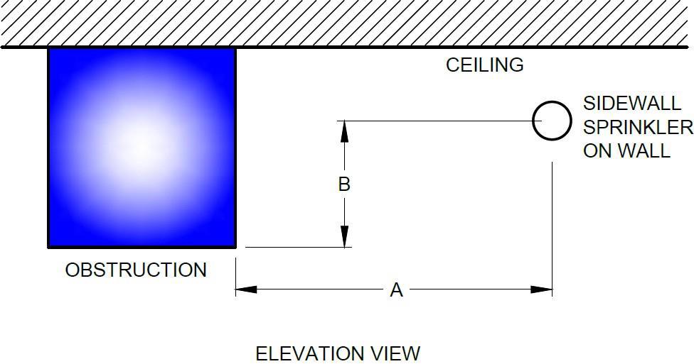
Sidewall Sprinkler Location in Relation to Obstructions (lighting, fan and similar fixtures) -Facing across the wall ( CPWD-Table 9.2)

Distance (A) between Sprinklers and the Obstruction on Side (mm) Maximum allowable Distance (B) between Deflector above bottom of Obstruction when Sprinkler can be allowed Up to 1200 Not allowed More than 1200 but less than 1500 25 More than 1500 but less than 1650 50 More than 1650 but less than 1800 80 More than 1800 but less than 1950 100 More than 1950 but less than 2100 150 More than 2100 but less than 2250 180 More than 2250 but less than 2400 230 More than 2400 but less than 2550 280 More than 2550 350

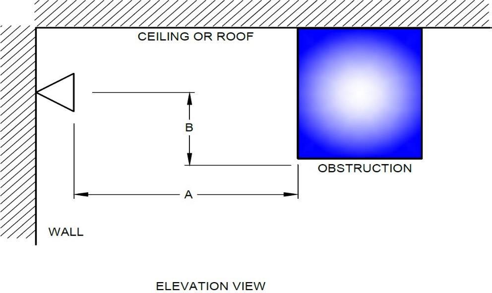
Sidewall Sprinkler Location in Relation to Obstructions (lighting, fan and similar fixtures)-Along the same wall (CPWD-Table 9.3 )

Distance (A) Between Sprinklers and the Obstruction on Side (mm) Maximum allowable Distance (B) between Deflector above bottom of Obstruction when Sprinkler can be allowed 100 to 150 25 More than 150 but less than 300 50 More than 300 but less than 450 80 More than 450 but less than 600 115 More than 600 but less than 750 150 More than 750 but less than 900 180 More than 900 but less than 1050 200 More than 1050 but less than 1200 230 More than 1200 but less than 1350 250 More than 1350 but less than 1500 300 More than 1500 but less than 1650 330 More than 1650 but less than 1800 350 More than 1800 but less than 1950 380 More than 1950 but less than 2100 430 More than 2100 but less than 2250 450

Sprinkler Location Below Ceilings [Clause 9.4.7.1],Table 9.1 (CPWD)

Type of ceiling Distance below ceilings (in mm) MIN MAX PREFERRED Combustible, asbestos cement sheets, wired glass and frangible 75 300 150 Combustible with exposed rafters and/or open joists 75 150 Non-combustible – either plane or arched or sloping 75 450 300

No of Sprinkler (NFPA-13)

PIPE SIZE Light hazard (Table 14.5.2.2.1) Ordinary Hazard (Table 14.5.3.4) Extra Hazard STEEL COPPER STEEL COPPER STEEL 25MM 2 Nos 2 Nos 2 Nos 2 Nos 1 Nos 32MM 3 Nos 3 Nos 3 Nos 3 Nos 2 Nos 40MM 5 Nos 5 Nos 5 Nos 5 Nos 5 Nos 50MM 10 Nos 12 Nos 10 Nos 12 Nos 8 Nos 65MM 30 Nos 40 Nos 20 Nos 25 Nos 15 Nos 80MM 60 Nos 65 Nos 40 Nos 45 Nos 27 Nos 85MM 100 Nos 115 Nos 65 Nos 75 Nos 40 Nos 100MM >100 Nos Check System Protection Area & Use Ordinary Haz…

Quick Reference-Fire Fighting (Part-5)

QUICK REFERENCE-FIRE FIGHTING (PART-5)

December 11, 2023 Leave a comment

Fire Pipe Support

Hanger rod diameter (mm) Nominal Pipes Diameter (mm) Spacing between supports (meter) Up to 25MM 8MM 2MM 32 to 50MM 8MM 2.5MM 65 to 80MM 10MM 2.5MM 100MM 12MM 2.5MM 150MM 16MM 3MM 200MM & above 16MM 3MM Extra supports shall be provided at the bends and at heavy fittings like valves to avoid undue stress on the pipes.

Support Spacing for Steel Pipe (ASME B31.1)

Pipe Size Water Gas 25.4 MM 2133.6 MM 2743.2 MM 50.8 MM 3048 MM 3962.4 MM 76.2 MM 3657.6 MM 4572 MM 101.6 MM 4267.2 MM 5181.6 MM 152.4 MM 5181.6 MM 6400.8 MM 203.2 MM 5791.2 MM 7315.2 MM 304.8 MM 7010.4 MM 9144 MM 406.4 MM 8229.6 MM 10668 MM 508 MM 9144 MM 11887.2 MM 609.6 MM 9753.6 MM 12801.6 MM

Thumb Rules for Pipe Support Spacing

As a rule of thumb, the spacing of pipe supports for steel pipes in liquid service, expressed in feet, may be taken as the nominal pipe size, expressed in inches, plus ten. For example, the spacing of pipe supports on a 6″ line will be approximately 6 + 10 = 16 feet

The Minimum Rate of Flow (NBC-2016) (Table 6.10.2.1.3)

Nominal Pipe Size Flow Rate Flow Rate 50 MM 100 gpm 380 L/Min 65 MM 150 gpm 568 L/Min 75 MM 220 gpm 833 L/Min 100 MM 390 gpm 1500 L/Min 125 MM 610 gpm 2300 L/Min 150 MM 880 gpm 3350 L/Min 200 MM 1560 gpm 5900 L/Min 250 MM 2440 gpm 9250 L/Min 300 MM 3520 gpm 13300 L/Min

Size of Mains (NBC-2016) Table 8

Size of the Mains Type of Building Remarks 100 mm with single outlet landing valves (a) Residential building (A): – 1) Dormitories – 2) Apartments – 3) Hotels Up to 45 m height (b) Educational buildings (B) – (c) Institutional buildings (C) Up to 30 m height (d) Assembly buildings (D) – (e) Business buildings (E) Up to 45 m height (f) Mercantile buildings (F) – (g) Industrial buildings (G) Up to 15 m heigh 150 mm with single outlet landing valves a) Hotels Above 45 m height b) Starred hotels c) Institutional buildings (C) Above 30 m height d) Business buildings (E) Above 45 m height e) Industrial buildings (G) Above 15 m height f) Storage buildings (H) Up to 15 m height g) Hazardous buildings (J) Up to 15 m height

Concealed Spaces Fire Protection (CPWD)

9.4.9.1 If the height of the concealed space at roof and floor is not greater than 0.8meter, the spaces shall be sprinkler protected only if they contain combustible materials or are constructed with combustible materials. Electrical cables with voltage less than 250 V, single phase, with a maximum of 15 cables per tray, are allowed. 9.4.9.2 Spaces between roofs and ceiling more than 0.8 m deep shall be sprinkler protected as follows: (i) Concealed spaces less than 5m2 in area shall not require sprinkler protection. (ii) Sprinkler heads shall be provided considering the space as any other area in the building. (iii) Sprinkler heads may be connected individually with the range/distribution pipes below, which shall be sized by taking the room and concealed space sprinklers cumulatively. (iv) Sprinkler heads for concealed space and for the room may be connected with separate range / distribution pipes connected, with common feed pipe. The common feed pipes shall be not less than 65 mm diameter.

Fire Fighting Accessories (CPWD)

Yard Hydrant (External Hydrant) Yard hydrants a ring of pipe shall be laid underground around the building at a minimum distance of 2 Meter but not more than 15 Meter from the building face. All internal risers shall be connected with this ring. The yard hydrants shall be easily accessible and should normally be provided near boundary wall/along road At least one External Hydrant post shall be provided for every 45 Meter All Yard hydrant outlets shall be situated 1 Meter above ground level. The stand posts shall be 80 mm in diameter for single headed hydrants. Underground pipe shall be laid at least 2m away from the face of the building preferably along the roads and foot paths. As far as possible laying of pipes under road, pavement and large open spaces shall be avoided. Pipes shall not be laid under buildings and where unavoidable, these shall be laid in masonry trenches with removable covers and cut-off valves shall be provided at points of entry and exit. Fire Service Inlet In order to facilitate feeding of water in the system by fire service, a 2 or 3 Way 63 mm diameter collecting head shall be provided and connected with each riser/down comer and the ring main with non-return valve and butterfly/sluice valve. This should be located at a place where fire brigade tender can reach. Fire Service connection It is for feeding water to underground storage tank by fire tenders. The static water storage tank shall be provided with a fire brigade collecting head with 4 number 63 mm diameter instantaneous male inlets arranged in a valve box at a suitable point at street level. Fire Brigade draw out collecting head Each of the static water sto…

Quick Reference -Fire Fighting (Part-6)

QUICK REFERENCE -FIRE FIGHTING (PART-6)

FIRE FIGHTING CLAUSE (AS PER GUJARAT FIRE PREVENTION AND LIFE SAFETY MEASURES REGULATIONS, 2023)

Clause

Head

Description

15.5.3

External Stairs:

The external stairs shall be constructed of non- combustible materials and any doorway leading to it shall have the required fire resistance. No external staircase, used as a fire escape, shall be inclined at an angle greater than 45° from the horizontal. External stairs shall have straight flight not less than 1250 mm wide with 250 mm treads and risers not more than 190 mm. The number of risers shall be limited to 15 per flight. Handrail s shall be of height not less than 700 mm and not exceeding 850 – 900 mm. There shall be provisions of balusters with maximum gap of 150 mm. 15.5.4

Horizontal Exit Door:

A horizontal exit shall be equipped with at least one fire/smoke door of minimum 2 hour fire resistance of self-closing type. Further, it should have direct connectivity to the fire escape staircase for evacuation. Doors in horizontal exits shall be open able at all times from both side 15.5.7

Exit Door ways

Size: No exit doorway shall be less than 1000 mm in width except assembly buildings where door width shall be not less than 2000 mm. Height: All doorways shall be not less than 2000 mm in heigh Opening Direction: Exit doorways shall open outwards, that is, away from the room, but shall not obstruct the travel along any exit. No door, when opened, shall reduce the required width of stairway or landing to less than 900 mm. Overhead or sliding doors shall not be installed. Exit door shall not open immediately upon a flight of stairs. A-landing equal to at least the width of the door (not less than 900mm) shall be provided in the stairway at each doorway, The level of landing shall be the same as that of floor, which it serves. Manual door should incorporate kick plate 300 mm high to withstand impact of wheelchair footrest where doors are glazed. Door handle and locks should be positioned between 900-1000 mm from floor level. Mirror: Mirrors shall not be placed in exit doors to avoid confusion regarding the direction of exit. 15.9 Corridors / Passageways & Stairs Case Flight: No flight shall contain more than 12 to 16 risers, but in residential buildings, in narrow plots and in high density Housing a single flight staircase may be permitted. Risers: The maximum height of a riser shall be 190mm. in a residential building and 16 cm. in any other occupancy. However, on an internal stairway within a dwelling unit a riser may be 25 cm high. Head room: The minimum head room in a passage under the landing of a staircase under the staircase shall be 2.2 meter. Tread Width: The minimum width of tread without nosing shall be 250 mm for internal staircase of residential buildings, other than fire escapes. This shall be 300 mm for assembly, hotels, educational, institutional, business and other buildings. The treads be constructed and maintained in a manner to prevent slipping. Hand Rail: Hand rail a minimum height of 0.9 meter from the center of the tread shall be provided. Floor indicator: The number of each floor shall be conspicuously painted in figures at least 15 cm large on the wall facing the fight of a stairway or at such suitable place as is distinctly visible from the fights. No Provision of Natural Ventilation : In case of any building having height more than 15 Meter and no provision of natural ventilation on either side of corridor, in such building, smoke exhaust system having make-up air and exhaust air system or alternatively, pressurization system with supply air system shall be required for the exit access corridors 15.8

Internal /Additional Staircases

Around Lift Shaft: A staircase shall not be provided around a lift shaft unless provided with fire stop door of 1 hour rating at every floor level and no other openings in the inside walls NO Services pass from Staircase: No gas piping, electrical panels& appliances or AC ducts shall be allowed in the stairway. However, service shafts/ ducts may be permitted. Electrical Shafts/ ducts shall have not less than2-hour fire resistance. For other service shafts/ ducts, the fire resistance shall be not less than 1 hour. Electrical Meter: Electric meters shall not be located below the staircase or along the exit route. Electric meters room shall be adequately ventilated & easily accessible Cooler Band : All steps, edges must have a contrasting color band of 50 mm width stretched entirely across the step width for uses other than residential use. Hand Rail: Continuous handrails shall be provided on both sides including the wall (if any) at two levels: upper at 850 mm – 900 mm and lower at 700 mm to be measured from the base of the middle of the treads to the top of handrails. Balusters/ Railing shall be provided in such a way that the width of staircase does not redu…

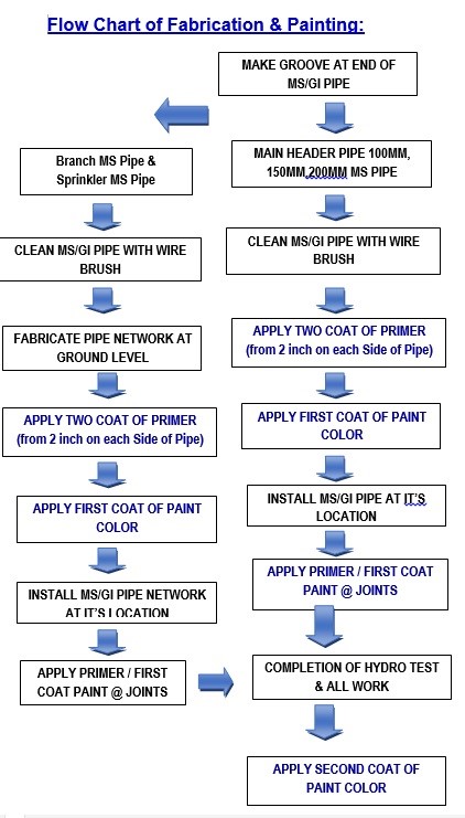
Method for Wrapping Coating & Holiday Test for Fire Fighting Pipe

METHOD FOR WRAPPING COATING & HOLIDAY TEST FOR FIRE FIGHTING PIPE

August 3, 2021 1 Comment

PURPOSE:

  • This method describes the detailed procedure for installation & Testing of Wrapping Coating and Holiday Test for Fire Pipes as per the standard Practice and Codes.

GENERAL EQUIPMENT & TOOLS:

  • The equipment that will be engaged for Installation of Fire Pipe works will be * Tool Box * Welding Machine * Grinding Machine * Cutting Machine * Chain Block * Pipe Wrench * Hand Tools-gloves. * Hammer * Portable Lights * Manual Excavation Tools * Removable Barricades * Scaffolding / Mobile scaffold * Ladder * Spirit Level * Marker * Holiday Test Machine * Measuring tape

STORAGE & MATERIAL HANDLING:

  • The storage area must be free from dust and the materials should be stacked in proper manner to avoid any damages. * The material shall be transported in their original packing to Site location. * All materials shall be stored in a covered warehouse in a location as cool as possible and protected from the ingress of dirt, dust, moisture, etc. * Any coating materials show evidence of deterioration due to weathering or damage due to mishandling while are in the custody contractor, shall be replaced by the contractor. * Chemicals must be stored in well ventilated location and away from direct sunlight.

INSPECTION OF MATERIALS

  • Inspection of Wrapping Coating: * Check the reference of delivered material against approved submittal. * Check the material against the purchase order. * Check Type of Material ,Size of Material , Make of Material * Chemicals such as paints, primer and thinner, check their expiration date before receiving. * Physical Damages Inspection: * In case of any damages observed during inspection, the Material shall be returned to the supplier for replacement.

SEQUENCES OF WRAPPING WORKS:

  • wrapping system shall comprise the followings sequences:

(A) SURFACE PREPARATIONS:

  • Prior to brush cleaning, all oil, grease on the pipe surface shall be thoroughly removed by flushing with suitable solvent and wiping with clean tags. * Rusted materials surface shall be adequate scrubbed manually with stiff wire brush where ever surface get rusted, prior to application of primer. * Surface shall be completely free from rust, mill scale, grease, weld spatter, weld slag, dirt, dust, oil and any other foreign matter and to be dry at time of application. * Oil and grease shall be removed using an approved solvent. White spirit and paint thinners are suitable solvents. Kerosene shall not be used. * Mechanical cleaning machines shall not employ knives or other tools, which may produce notches or gauges on the pipe surface. * Blast cleaning machines shall be maintained in correct adjustment and replacement tools shall be available throughout the cleaning process. * All weld joints shall be cleaned manually with stiff wire brush/buffing * The coat of primer shall be given as soon as practicable and before detrimental corrosion or recontamination occurs. The cleaned surface shall never be left unprotected overnight. * The cleaning method employed shall not result in thinning of the pipe wall beyond the limits of the pipe specification. * Cleaning shall be carried out immediately before application of the priming coat and shall be to the satisfaction of OWNER. If the outside of the pipe becomes contaminated with any foreign matter.

(B) APPLICATION OF PRIMER:

  • Immediately after cleaning the surface shall be applied with one coat of primer before application of coal tar wrapping. The entire surface of pipe should be primed. * The primer shall be applied in a thin layer without runs, sags, drips, holidays (gaps or voids) or other defects. * If any defects may be found in the primed surface, the pipe shall be re-cleaned and primed to the required standard and to the satisfaction of principal/engineer. * No specific time gap between two coats needs to be maintained but after the coat of primer, the coating should before the primer is completely hardened. * The primer shall be suitable for brush or spray application and still form at thin uniform coating with an approximate 40 micrometer dry film thickness according to vendor’s instruction. * Freshly primed pipe shall be properly supported on racks, and allowed to be uncontaminated by moisture, dirt or other foreign matter. * If application is done in cold weather, the surface of the pipe shall be pre- heated until it is warm to touch and traces of moisture are removed and then primer shall be applied and allowed to dry. * Coating and wrapping shall not be started until that section of line has been tested and accepted. * The primer shall be suitable for brush or spray application and still form at thin uniform coating with an approximate 40 micrometer dry film thickness according to vendor’s instruction. * Primer shall be applied at an average rate 0.12 liter per…

Method of Statement for Fire Fighting Works (Part-1)

METHOD OF STATEMENT FOR FIRE FIGHTING WORKS (PART-1)

PURPOSE:

This method describes the detailed procedure for installation and Testing of Wet Raiser Fire Protection System, Pipes, Sprinkler, Fire Pumps, Valves and Fire Fighting Accessories as per the standard Practice and Codes.

GENERAL EQUIPMENT & TOOLS:

The equipment that will be engaged for Installation of Fire Fighting works will be

  • Tool Box * Welding Machine * Drilling Machine with various Bits * Grinding Machine * Cutting Machine * Threading Machine * Chain Block * Pipe Wrench * Hand Tools-gloves. * Hammer * Portable Lights * Manual Excavation Tools * Removable Barricades * Scaffolding / Mobile scaffold * Ladder * Spirit Level * Screwdriver, Pliers, Spanner. * Marker * Pressure gauge * Level gauge / Spirit level. * Measuring tape * Pressure test pump.

STORAGE & MATERIAL HANDLING:

  • The storage area must be free from dust and the materials should be stacked in proper manner to avoid any damages. * The Material shall be stored in designated area of the Store to protect the M.S Pipe and Other Fire Fighting Accessories against effects of weather and environment. * The material shall be transported in their original packing to Site location. * The pipes will be stacked in the site store on a proper stand on wooden loft on a flat surface at a height not exceeding 1.7m. From the bottom layer. * All open ends of pipes will be covered to protect from foreign matter, dirt/debris * Fittings will be separately packed and stored as per the sizes required for the project. * Chemicals must be stored in well ventilated location and away from direct sunlight.

INSPECTION OF MATERIALS: 

  • Inspection of Pipe / Valve / Flanges: * Check Type of Material ,Size of Material , Make of Material. * Chemicals such as paints, primer and thinner, check their expiration date before receiving. * Physical Damages Inspection: * In case of any damages observed during inspection, the concern report will be issued and Material shall be returned to the supplier for replacement.

INSTALLATION PROCEDURE:

(1) PIPE HANGER / SUPPORT INSTALLATIONS

  • Piping Route will be the as per most advantageous manner possible with respect to headroom, valve access, opening and equipment clearance, and clearance for other work. * The Line layout should be verified from Site in charge. * After marking the pipe routes, the anchoring points will be drilled according to the required support spacing as shown on the approved shop drawings.

Pipe Diameter (mm) Maximum Hanger Spacing (mm) Rod Size (mm) 25 2000 8 32 2500 8 40 2500 8 50 2500 8 65 2500 10 80 2500 10 100 * 2500 * 12 * 150 * 3000 * 16 * 200 * 3000 * 16 * * As per Site Requirement Fabrication Support may be used.

  • Mark out the location of hanger thread rods for pipe installation as per the approved construction drawing. * Fasteners and fully threaded rods shall be used for installing the pipe supports. The sizes of pipe supports and installation shall be in accordance with manufacturer’s recommendations. * For Single pipes of size 100 mm and above, with the prior approval 50xx50xx6 mm MS Angle iron and for Double Pipe 75x75x6mm with U Clamp with Fastener may be used for Supporting horizontal Pipe from ceiling. * Drill the marked position for hangers and supports by using the drill bit of appropriate size. * Fix the unfix anchor at drilled position by gentle and uniformly hammering. * Fix the threaded rod of appropriate diameter and size & length in the anchor by twisting by turning. * After fixing the threaded rod, insert a washer of appropriate size in to the rod. * Finally fix the washer near to the slab by tightening a nut over it, this will improve the strength and load bearing capacity of threaded rod. * For installing pipes vertically or horizontally inside the building standard pipe supports of reputed make shall be used. Following supports shall be used. * Clevis Hangers or MS Chanel for horizontal supports to adjust varying heights. * The Pipe route should be min 500mm away from wall. * Supports will be arranged as near as possible to pipe joints and any change in direction. * Vertical Riser Support: * Risers shall be supported by pipe clamps or by hangers located on the horizontal connections within 24 inches (0.6 Meter) of the centerline of the riser.

(2) PIPE WELDING / FABRICATION:

  • Welding Machine: * Welding machines shall be in good working condition and shall have proper control for regulating current. * Location of welding machines and the distribution boards to be connected with them shall be verified by site electrical Team to avoid overloading of the distribution boards, cables and electrical power sources. * All welding Machine ,other Electrical Tools, the electric cables, distribution boards and connections for machines shall be carefully checked once a Month to maintained it in a good working condition. * Weld…
Cover image
N

Method of Statement for Fire Fighting Works (Part-2)

METHOD OF STATEMENT FOR FIRE FIGHTING WORKS (PART-2)

(5) VERTICAL RISERS

  • Vertical risers shall be parallel to walls and column lines and shall be straight and in plumb. Risers passing from floor to floor shall be supported at each floor by MS angle with clamp as per specification of pipe support. * The space in the floor cut outs around the pipes work may be closed using cement concrete (1:2:4 mix) or steel sheet, from the fire safety considerations, taking care to see that a small annular space is left around the pipes to prevent transmission of vibration to the structure. * Riser shall have suitable supports at the lowest point.

(6) SPRINKLER HEADS & ACCESSORIES

  • Installation of sprinkler heads will be done after pipe work flushing is completed. * Apply the PTFE tape only to the male portion of the sprinkler and install the upright sprinkler head using the wrench provided by the manufacturer, and in such a way that the arms are parallel to the branch pipe. Maintain a clearance of 1” between the deflector of upright sprinkler and ceiling. Ensure that sprinkler heads have the correct finish and temperature rating. * For fixing sprinkler heads, 15 mm. dia. M.S. Socket is to be screwed to range pipes at the locations as’ per drawings. Dead plug shall be fixed in the socket. * If sprinkler head is to be provided away from range pipe, M.S. Pipe nipple of suitable size be used to extend the sprinkler head and socket is welded at desired location. * During occupation of the building, sprinkler heads shall be provided in place of dead plugs. Teflon tape shall be used on threaded portion.

(7) FIRE HOSE REEL / FIRE HOSE CABINETS

  • Check cabinets are approved size and dimension. Inspect for signs of damage.

  • Locate exact location of these Cabinets as per approved shop drawings and with careful measure of elevation and plumb.

  • Fix cabinet using recommended anchor and bolts. Proceed with installation of accessories, lock shield valve, landing valves, etc. taking in consideration of approval for these devices. * Prior to the installation Foreman will read, understand and strictly follow the manufacturer’s instructions. * Examine the location of the hose reel cabinets and ensure that opening is sufficient for fixing all equipment and the mounting height of the hose valve and hose racks is as per the approved shop drawings and to the requirements. Hose reel, hose valves and fire extinguishers are of approved type and have the correct rating. * The cabinet (without the equipment) will be installed where applicable. Branches to the hose rack (reel) / hose valve will be installed on site to ensure actual entry point to the cabinet. Location of Pipe sleeves shall be as per approved drawings. * Hose reel & valve will be installed as per the manufacturer’s instructions at the correct mounting height. * Keep fire extinguisher inside the cabinet along with the hose rack. Ensure that the top of the wall mounted extinguisher do not exceed from the levels as per approved drawing and specification.

(8) DRAIN PIPING OF THE SYSTEM:

  • Fittings will be of the eccentric pattern to ensure proper drainage and the elimination of air pockets wherever necessary. * In Sprinkler Network at far end Drain Pipe shall be provided on last Sprinkler to remove Air from Sprinkler Network.

(9) SLEEVES

  • The branch lines will be hanged to the proper level and will be connected to the cross main. Where piping is embedded or passing through masonry or concrete, sleeves will be provided as per specification mostly of MS or GI material. * Pipe sleeves of diameter larger than the pipe by least 50 mm shall be provided wherever pipes pass through walls and the annular spaces shall be filled with felt and finished with retaining rings.

(10) SEALANT

  • After the removal of the concrete forms and installation of the pipeline, the annular space between the sleeve and the pipe shall be filled with caulking material leaving enough space at both ends of the sleeve for sealing.

(11) UNDER GROUND PIPE

  • Where mild steel pipes are to be buried under ground the same shall be treated anti corrosion treatment. The top of the pipes shall be not less than 100 cm below the ground level. * Where this is not practicable, permission of the Engineer-in-charge shall be obtained for burying the pipes at lesser depth. * After the pipes have been laid, the trench shall be refilled with the excavated soil and rammed and any extra soil shall be removed from the site of work by the contractor. * Underground pipe shall be laid at least 1 meter away from the face of the building preferably along the roads and foot paths. * As far as possible lying of pipes under road, pavement and large open spaces shall be avoided. * To facilitate detection of leak and isolation of defective portion of pipe, valves shall be provided in underground pipe at suitable locations. * A…
N

Guideline for Manual Call Point

GUIDELINE FOR MANUAL CALL POINT

January 7, 2026 1 Comment

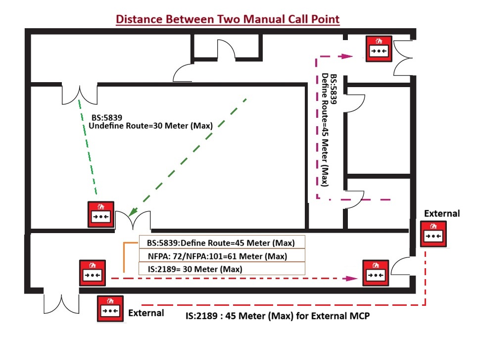
MANUAL CALL POINT REFERENCE Area Code Clause No Descriptions Mounting Height NFPA 72 17.14.5 The operable part must be between 1.07 meter to 1.22 meter above the finished floor. BS 5839-1:2025 20.2 Typically mounted at 1.4 meters (0.2m above or 0.3m below) allowing placement between 1.1 meter and 1.6 meter. For disabled access, heights may be lowered to 0.9 meter to 1.2 meter. IS 2189 6.3.8 Call points shall be fixed at a height of 1.4 meter above the surrounding floor level, at easily accessible, we illuminated and conspicuous positions, which are free of obstructions. From Door Distance NFPA 72 17.15.9.6 pull stations are required to be located within 1.5 meters of each exit doorway on every floor, ensuring they are easily reachable during emergencies. NFPA 101 9.6.2.3 the manual fire alarm box shall be located within 1525 mm of exit doorways. NFPA 101 9.6.2.4 Manual fire alarm boxes shall be mounted on both sides of grouped openings over 40 ft (12.2 meter) in width, and within 1525 mm of each side of the opening. Travel Distance NFPA 101 9.6.2.5 No horizontal distance on that floor exceeding 200 ft (61 meter) shall need to be traversed to reach a manual fire alarm box. BS 5839-1:2025 20.2 MCPs must be on escape routes and Distribution of MCPs should be such that no one need travel more than 45 meter in certain route (or 30 meter if layouts are uncertain). For disabled residents this should be adapted to within 25 meter to 16 Meter of each other. For high-risk areas (e.g. kitchens or cellulose paint spraying) a MCP should be sited in close proximity. NFPA 72 17.15.9.5 Additional manual fire alarm boxes shall be provided so that the travel distance to the nearest manual fire alarm box will not exceed 200 ft (61 meter), measured horizontally on the same floor. IS 2189 6.3.8 Manual call points shall be so located that, to give an alarm, no person in the premises has to travel distance of more than 30 meter to reach them. When manual call points are also installed external to the building, the travel distance shall be 45 meter IS 2189 6.3.8 Where necessary, the travel distance may require to be reduced to less than 30 meter, for example, where there is difficulty in free access within the risk or in potentially dangerous risks. Location BS 5839-1:2025 Not placing MCPs at non-final exits or in unsupervised areas like shopping centers. IS 2189 6.3.8 Manual call point shall be located preferably near entry to staircases at various levels. NBC 2016 J-9.1.4 Manual call station(s) shall be provided at central location(s) on each platform (near emergency plunger) and at least two on the concourse, on each sidewall. When the concourse is in two halves, at least one manual call station shall be provided on each side. BS 5839-1:2017 20.2 MCPs should be located on escape routes and, in particular, at all story exits and all exits to open air that lead to an ultimate place of safety (whether or not the exits are specifically designated as fire exits) Staircase Landing BS 5839-1:2017 20.2 MCPs should not be located on stairway landings, as persons travelling down the stairway might operate an MCP several floors below that on which a fire is located, resulting in evacuation of inappropriate areas. Protecting Cover / Duct Proof BS 5839-1:2025 MCP may provide fitting covers or guards to prevent false alarms and damage. NFPA 72 17.14.7 Listed protective covers shall be permitted to be installed over single- or double-action manually actuated alarm initiating devices. IS 2189 6.3.8 Manual call points shall be housed in dust pre of and moisture proof enclosure properly sealed with rubber lining. Recess Mounting IS 2189 6.3.8 Where the call points are not visible from the front as in the case of a long corridor, they shall be surface mounted or semi-recessed in order to present a side profile area of not less than 750 mm. BS 5839-1:2017 20.2 MCPs may be flush-mounted in locations where they will be seen readily, but, where they will be viewed from the side (e.g. corridors), they should be surface mounted or only semi-recessed with the front face proud of the mounting surface by no less than 15 mm. MCP Glass Size & Thickness IS 2189 6.3.8 The glass surface shall be minimum 30 mm in area and glass thickness shall not exceed 2 mm. MCP/ Pull Station NFPA 72 17.14.6 Manually actuated alarm-initiating devices shall be permitted to be single action or double action. NBC 2016 6.4.2.2 The manual call points shall be break glass and not pull stations. Color NFPA 72 17.14.8.3 Unless installed in an environment that precludes the use of red paint or red plastic, manual fire alarm boxes shall be Red in color.

Fire Door / Fire Wall / Fire Sealant / Fire Rated Equipment’s Guideline

FIRE DOOR / FIRE WALL / FIRE SEALANT / FIRE RATED EQUIPMENT’S GUIDELINE

August 29, 2025 Leave a comment

Fire Door / Fire Wall / Fire Sealant / Fire Rated Equipment’s

Code Clause No Area Descriptions NBC-2016 2.24 Fire Tower Wall / Fire Tower Door Fire Tower An enclosed shaft having protected area of 120 min Fire resistance rating comprising protected lobby, staircase and Fireman lift, connected directly to exit discharge or through exit passageway with 120 min Fire resistant wall at the level of exit discharge to exit discharge. The Fire fighting shaft shall be equipped with 120 min Fire doors. NBC-2016 5.1.1(g) Fire Fighting Shaft (Fire Hose Cabinet) Door Hydrants for firefighting and hose reels shall be located in the lobby in firefighting shaft. Those hydrants planned to be provided near fire exit staircase on the floor shall be within 5 m from exit door in exit access. Such hydrant cabinet may finish with doors to meet interior finishes with requirement of glass panel to provide visibility to the installations inside and inscribed with the word: FIRE HOSE CABINET of letter size 75 mm in height and 12 mm in width. Such door of the fire hose cabinet need not be fire resistant rated. The location of such cabinets shall be shown on floor plan and duly displayed in the landing of the respective fire exit staircase. NBC-2016 3.4.5.4 Electrical Shaft Door The inspection door for electrical shafts/ducts shall be not less than 120 min Fire resistance. Model Building-Bye-laws-2016 7.14.d Electrical Shaft Door The inspection panel doors and any other opening in the shaft shall be provided with airtight Fire doors having Fire resistance of not less then 1 hour. Gujarat Fire Prevention and Life Safety Regulations, 2023 15.2 Electrical Shafts Door Electrical Shafts shall have not less than 2 hours Fire resistance Model Building-Bye-laws-2016 7.13.a Service Shafts Door Service duct shall be enclosed by walls and door, if any, of 2 hours Fire rating. If ducts are larger than 10 sq m. the floor should seal them, but provide suitable opening for the pipes to pass through, with the gaps sealed. Gujarat Fire Prevention and Life Safety Regulations, 2023 15.2 Service Shafts Door Services Shafts other than Electrical Shaft, the Fire resistance shall be not less than 1 hour. NBC-2016 3.4.5.4 Plumbing Shaft Door (Inside the Building) For plumbing shafts in the core of the building, with shaft door opening inside the building, the shafts shall have inspection doors having Fire resistance rating not less than 30 min NBC-2016 3.4.5.4 Plumbing Shaft Door (Outside the Building) For plumbing shafts doors which open in wet areas or in naturally ventilated areas or on external wall of the building, the shafts may not require doors having any specified Fire rating. NBC-2016 3.4.5.4 Service Shafts Sealing Service ducts and shafts Openings in walls or floors which are necessary to be provided to allow passages of all building services like cables, electrical wirings, telephone cables, plumbing pipes, etc, shall be protected by enclosure in the form of ducts/shafts having a Fire resistance not less than 120 min. Central Electricity Authority 38.2 Service Shafts Sealing No other service pipes shall be taken along the ducts provided for laying power cables. All ducts provided for power cables and other services shall be provided with Fire-barrier at each floor crossing NBC-2016 3.4.5.4 Electrical Cable Sealing The space between the electrical cables/conduits and the walls/slabs shall be filled in by a Fire stop material having Fire resistance rating of not less than 120 min. This shall exclude requirement of Fire stop sealing for low voltage services shaft. NBC-2016 3.4.6.1 Electrical Shaft Sealing The electric distribution cables/wiring shall be laid in a separate shaft. The shaft shall be sealed at every floor with Fire stop materials having the same Fire resistance as that of the floor. IS IS 3034 Electrical Cable Entry Sealing All cable entries in the switch gear room shall be effectively sealed by use of Fire stops. Model Building-Bye-laws-2016 7.14.a Electrical Shaft Sealing The electric distribution cables/wiring shall be laid in a separate duct shall be sealed at every floor with non-combustible material having the same Fire resistance as that of the duct. Gujarat Fire Prevention and Life Safety Regulations, 2023 15.11 Electrical Services Shaft Sealing The electric distribution cable/wiring shall be laid in a separate duct. The duct shall be sealed at every floor with non-combustible materials having the same Fire resistance as that of the duct. NBC-2016 3.4.6.3 Meter Room Door Meter rooms on upper floors shall not open into staircase enclosures and should be ventilated directly to open air outside or in electrical room of 120 min Fire resistant walls. Gujarat Fire Prevention and Life Safety Regulations, 2023 15.11 Electrical Servi…

Cover image
N

Hydrostatic Test Pressure & Working Pressure Rating for Fire System

HYDROSTATIC TEST PRESSURE & WORKING PRESSURE RATING FOR FIRE SYSTEM

July 28, 2025 Leave a comment

FIRE SYSTEM HYDROSTATIC TEST PRESSURE RATING:

  • The Hydrostatic test for a Fire water line System is to pressurize the System with water to a level beyond its normal operating pressure to identify any leakages and weakness in Pipes and its components to ensure that Fire System can withstand overpressure in Fire scenarios. * Hydro test can help to Identifying and repairing these leaks before the system is put into service to prevents potential safety hazards, environmental damage, and costly downtime. * This test is crucial for verifying that the Fire System can withstand potential pressures during a Fire event. * The Test Pressure is very important to identify the leakages, if pressure is too high than it may be damage Fire Pipes & it’s components and if the pressure is too low than it will not identify various leakages or weak point of the Fire System in potential overpressure scenarios. 

Fire Sprinkler System Hydrostatic Test Pressure Rating

Code

Descriptions

NFPA 13, Section 29.2.1.1 Hydrostatic Tests Acceptance: New or modified sprinkler installations system working pressure Less than 150 PSI (10 Kg/Cm2) should a hydrostatic pressure test of no less than 200 PSI (13.8 Kg/Cm2) for 2 hours with zero loss in pressure at the reference gauge or visual observation of a leak. NFPA 13, Section 29.2.1.3 Where the system having working pressure above 150 PSI (10Kg/Cm2) then It must be tested to the system working pressure + 50 PSI (3.4 Kg/Cm2). Example: For 200 PSI Working Pressure have Testing Pressure of =14+3.4 =17.4 Kg/Cm2 NFPA 13, Section 29.2.1.4 Where fire pump is used for a system, testing pressure shall be determined by using the shut off pressure of the pump, excluding any limiting device. NFPA 13, Section 10.10.2.2 Underground Piping: All piping and attached appurtenances subjected to system working pressure shall be hydrostatically tested at 200 PSI (13.8 Kg/Cm2) or 50 PSI (3.5 Kg/Cm2) in excess of the system working pressure, whichever is greater, and shall maintain that pressure ±5 PSI (0.35 Kg/Cm2) for 2 hours. NFPA 13, Section 25.2.1.1 Systems Acceptance: All piping and attached appurtenances subjected to a working pressure less than 150 PSI (10Kg/Cm2) shall be hydrostatically tested at 200 PSI (13.8 Kg/Cm2) and shall maintain that pressure without loss for 2 hours. Portions of systems where working pressures in excess of 150 PSI (10.4 Kg/Cm2) shall be tested at a pressure of 50 PSI (3.5 bar) in excess of working pressure NFPA 20, Section 14.1.2.1 Suction and discharge piping shall be hydrostatically tested at not less than 200 PSI (13.8 Kg/Cm2) pressure or at 50 PSI (3.4 Kg/Cm2) in excess of the maximum pressure to be maintained in the system, whichever is greater. The pressure shall be maintained without loss for 2 hours NFPA 25, Section 6.3.2.1 A working pressure less than 150 PSI (10Kg/Cm2) shall be Hydrostatic tests of not less than 200 PSI (13.8 Kg/Cm2) pressure for 2 hours, or at 50 PSI (3.4 Kg/Cm2) in excess of the maximum pressure, where maximum pressure is in excess of 150 PSI (10.3 bar), shall be conducted every 5 years on manual standpipe systems and semiautomatic dry standpipe systems, including piping in the fire department connection. NFPA 25, Section 13.7.4 The piping from the fire department connection to the fire department check valve shall be hydrostatically tested at 150 PSI (10 Kg/Cm2) for 2 hours at least once every 5 years NFPA 14 , Section 11.4.1 requires all FDCs to be tested hydrostatically at not less than 200PSI (14 Kg/Cm2) or 50PSI (3.5 Kg/Cm2) in excess of the system working pressure, whichever is greater for a duration of 2 hours. IS 15105:2, Section 10.1.6 The installation piping (from the pumphouse up to the installation valve and also the installation piping with sprinklers) shall be capable of withstanding for two hours a pressure equivalent to 150% of the maximum working pressure. (maximum Pressure may be derive from Fire Pump Data Sheet) IS 13039, Section 7.1 After installation the system should be capable of withstanding pressure equal to 150% of the maximum working pressure for 2 hour. (maximum Pressure may be derive from Fire Pump Data Sheet) IS 3844 , Section 8.1 The system should be tested before use by charging with water to a pressure of 700 kPa (7 kg/Cm2) measured at the inlet for a period of at least 30 minutes. During this period, an inspection of the system should be done to check that no leakage of water is taking place at any of the joints or landing valves and the pressure in the system does not drop by more than 50 kPa (0.5 Kg/Cm2). BS 9251, Section 6.2.2 The installation pipework should be pressurized to a minimum pressure of 15 bar (15.2 Kg/Cm2) or to 1.5 times the maximum working pressure, whichever is the greater, for 1 hour. If the sprin…

1. Calculation of Cable Tray Size

CALCULATION OF CABLE TRAY SIZE

Calculate Size of Cable Tray for Following Cable Schedule. Cable Tray should be perforated and 20% spare Capacity. Distance between each Cable is 10mm. Cable are laying in Single Layer in Cable Tray. (1) 2 No’s of 3.5Cx300 Sq.mm XLPE Cable having 59.7mm Outer Diameter and 5.9 Kg/Meter weight (2) 2 No’s of 3.5Cx400 Sq.mm XLPE Cable having 68.6mm Outer Diameter and 6.1 Kg/Meter weight (3) 3 No’s of 3.5Cx25 Sq.mm XLPE Cable having 25mm Outer Diameter and 0.5 Kg/Meter weight

CALCULATION:

TOTAL OUTER DIAMETER OF ALL CABLE PASSING IN TO CABLE TRAY:

  • Diameter of 300Sq.mm Cable =No of Cable X Outer Diameter of Each Cable * Diameter of 300Sq.mm Cable =2X59.7 = 119.4 mm * Diameter of 400Sq.mm Cable =No of Cable X Outer Diameter of Each Cable * Diameter of 400Sq.mm Cable =2X68.6= 137.2 mm * Diameter of 25Sq.mm Cable =No of Cable X Outer Diameter of Each Cable * Diameter of 25Sq.mm Cable =3X28= 84 mm * Total Diameter of All Cables laying in Tray = (119.4+137.2+54)mm * Total Diameter of All Cables laying in Tray = 340.6mm

TOTAL WEIGHT OF CABLES PASSING IN TO CABLE TRAY:

  • Weight of 300Sq.mm Cable =No of Cable X Weight of Each Cable * Weight of 300Sq.mm Cable =2X5.9= 11.8 Kg/Meter * Weight of 400Sq.mm Cable = No of Cable X Weight of Each Cable * Weight of 400Sq.mm Cable =2X6.1= 12.2 Kg/Meter * Weight of 25Sq.mm Cable = No of Cable X Weight of Each Cable * Weight of 25Sq.mm Cable =3X0.5= 1.5 Kg/Meter * Total Weight of All Cables laying in Tray = (11.8+12.2+1.5) Kg/Meter * Total Weight of All Cables laying in Tray =25.5 Kg/Meter

TOTAL WIDTH OF ALL CABLES:

  • Total Width of all Cables = (Total No of Cable X Distance between Each Cable) + Total Cable Outer Diameter * Total Width of all Cables = (7 X 10) + 340.6 * Total Width of all Cables = 410.6 mm * Taking 20% Spare Capacity of Cable Tray * Final Width of all Cables = 1.2%X4106.6 * Calculated Width of All Cables = 493 mm

TOTAL AREA OF CABLE:

  • Total Area of Cable = Final width of Cables X Maximum Height Cable * Total Area of Cable = 493 X 69.6 =28167 Sq.mm * Taking 20% Spare Capacity of Cable Tray * Final Area of all Cables = 1.2%X28167 * Calculated Area of all Cable =33801 Sq.mm

CASE-(I):

  • Considering Single Run of Cable Tray having Size of 300X100mm, 120Kg/Meter Weight Capacity * Area of Cable Tray =Width of Cable Tray X Height of Cable Tray * Area of Cable Tray =300X100 = 30000 Sq.mm * Checking Width of Cable Tray * Calculated Width of Cable Tray as per Calculation=No of Layer of Cable X No of Cable Tray Run X Width of Cables * Width of Cable Tray as per Calculation=1X1X493 =493 mm * Checking Depth of Cable Tray * Actual depth of Cable Tray = No of Layer of Cable X Maximum Diameter of Cable * Actual depth of Cable Tray=1X68.6 =68.6mm * Checking Weight of Cable Tray * Actual Weight of Cables=25.5 Kg/Meter

Results:

  • Calculated Cable Tray width (493mm)> Actual Cable Tray width ( 300mm) = Faulty Selection * Calculated depth of Cable Tray (68.6mm)< Actual Depth of Cable Tray (100mm) = O.K * Calculated Weight of all Cables (25.5Kg/Mt) < Actual Weight of Cable Tray (125.5 Kg/Mt) =O.K * Required to select higher size Cable Tray due to small Cable Tray width.

CASE-(II):

  • Considering Single Run of Cable Tray having Size of 600X100mm, 120Kg/Meter Weight Capacity * Area of Cable Tray =Width of Cable Tray X Height of Cable Tray * Area of Cable Tray =600X100 = 60000 Sq.mm * Checking Width of Cable Tray * Width of Cable Tray as per Calculation=No of Layer of Cable X No of Cable Tray Run X Width of Cables * Width of Cable Tray as per Calculation=1X1X493 =493 mm * Checking Depth of Cable Tray * Actual depth of Cable Tray = No of Layer of Cable X Maximum Diameter of Cable * Actual depth of Cable Tray=1X68.6 =68.6mm * Checking Weight of Cable Tray * Actual Weight of Cables=25.5 Kg/Meter

Results:

  • Calculated Cable Tray width (493mm)< Actual Cable Tray width ( 600mm) = O.K * Calculated depth of Cable Tray (68.6mm)< Actual Depth of Cable Tray (100mm) = O.K * Calculated Weight of all Cables (25.5Kg/Mt) < Actual Weight of Cable Tray (125.5 Kg/Mt) =O.K * Remaining Cable Tray width Area =100%-(Calculated Cable tray width/ Actual Cable Tray Width) * Remaining Cable Tray width Area =100%-(493/600)% =17.9% * Remaining Cable Tray Area =100%-(Calculated Cable tray Area/ Actual Cable Tray Area) * Remaining Cable Tray Area =100%-(33801/60000) =43.7% * Selection of 600X100 Cable Tray is O.K

CONCLUSION

  • Size of Cable Tray= 600X100mm * Type of Cable Tray=Perforated * No of Cable Tray Run= 1No * No of layer of Cables in Cable Tray=1 Layer * Remaining Cable Tray width Area =17.9% * Remaining Cable Tray Area =43.7%

2. Calculate Cable Trunking Size

CALCULATE CABLE TRUNKING SIZE

Example: Calculate PVC Trunking size for following Power Cables running through Trunking .Consider 10% as Future expansion

  • 30 No’s of 1.5 Sq.mm Stranded Cables * 50 No’s of 2.5 Sq.mm Stranded Cables * 20 No’s of 4 Sq.mm Stranded Cables

Cable Factor for Trunking as per IEEE

Type of Cable Size of Cable Factor Solid 1.5 7.1 Solid 2.5 10.2 Stranded 1.5 8.1 Stranded 2.5 11.4 Stranded 4 15.2 Stranded 6 22.9 Stranded 10 36.3 Stranded 16 50.3 Stranded 25 75.4 Stranded 35 95 Stranded 50 132.7 Stranded 70 176.7 Stranded 95 227 Stranded 120 284 Stranded 150 346

Trunking Factor As per IEEE

Trunking Size (mm) Factor 75 X 25 738 50 X 37.5 767 100 X 50 993 50 x 50 1037 75 X 37.5 1146 100 X 37.5 1542 75 X 50 1555 100 X 50 2091 75 X 75 2371 150 X 50 3161 100 X 75 3189 100 X 100 4252 150 X 75 4787 150 X 100 6414 150 X 150 9575

CALCULATIONS:

  • As per Table Cable Factor for 1.5 Sq.mm Stranded Cable=8.1 * As per Table Cable Factor for 2.5 Sq.mm Stranded Cable=11.4 * As per Table Cable Factor for 2.5 Sq.mm Stranded Cable=22.9 * Total Cable Factor= No of Cables X Cable Factor * Total Cable Factor=(30X8.1)+(50X11.4)+(20X22.9) * Total Cable Factor=1271 * Total Cable Factor After 10% Future Expansion=1271+127 =1398 * As per Table Suitable Size for PVC Trunking for Cable Factor 1398 is 100 X 37.5

SUITABLE PVC TRUNKING IS 100 X 37.5 MM

Cover image
(1) CABLE:

3. Calculate Conduit Size for Wire / Cables

CALCULATE SIZE OF CONDUIT (EXCEL)

ScreenHunter_01 Jan. 04 20.28

  • Calculate Total Area of Multiple Cables. * Calculate Total Area of Conduit for Multiple Cables. * Calculate Fill up area of Conduit. * Calculate % Fill up area of Conduit. * Calculate No of Conduits for Multiple Cables. * Calculate Size of Conduits for Multiple Cables.

FREE DOWNLOAD