Site logo
Electrical Engineering Academy
L

Method for Installation of Conceal & Surface Conduits (Part-2)

METHOD FOR INSTALLATION OF CONCEAL & SURFACE CONDUITS (PART-2)

September 18, 2021 1 Comment

4.FILLING CHASING AREA:

  • All grooves, chases shall be properly filled and concreted and finished up to the wall surface before plastering of walls is taken up. The conduit boxes, accessories, joints, etc. shall be laid along with the conduits. The chases shall be sufficiently deep and properly filled with cement mortar. * Where conduits pass through expansion joints in the building, adequate expansion fittings or other approved services shall be used to take care of any relative movement. As far as possible, chasing of wall to embed the conduits to be avoided. * Chasing is filled by Cement mortar 1:5 ratio(1 portion of the cement+5 portion of sand) shall be used for patchwork in chased area and its surface is rough so main plaster will easily joint on chasing area. * Curing shall be carried out for a minimum of three days. * Make sure the conduits are not visible from outside their route which could lead to improper plastering.

5.WIRE MESH:

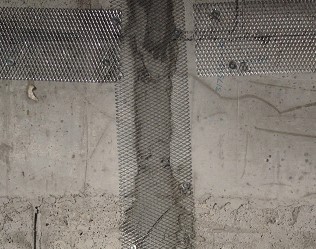
  • After chasing area is filled by mortar, Chicken (wire) mesh and GI nails shall be applied on chasing area to avoid hair crack in plaster. * Width of Chicken Mesh is slightly larger than chasing Area. After installation of Chicken mesh final Plaster should be done. * Make Sure that Nails for Wire Mesh should not damage the Buried PVC Conduit.

A

6.SURFACE CONDUCTING:.

  • Take the approved Drawings of Electrical conduit Shop Drawing with section details, MEP coordination drawing with section details and Architectural Drawings. * Ensure that the civil people have finished block wall and Plastering with adequate curing and clearance is given to proceed for electrical works. * Check the required reference markings are available for FFL (finished floor levels). * All required materials shall be shifted and stored under safe custody near workplace on daily basis as per planned quantity.

1 ) MARKING OF CONDUITS:

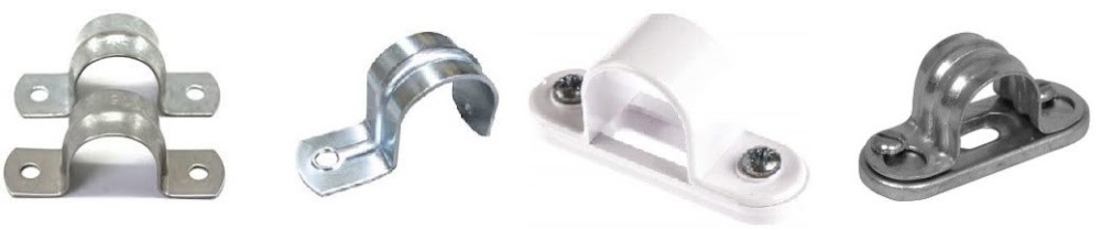
  • Site Engineer will carry out a site survey where the PVC Conduit will be installed as per approved shop drawings. * Mark the exact position of the conduit route with the blue marker string and then install conduit saddles. * All runs must be installed as a complete system before any conductors are pulled into them. In other words, a run of conduit (to include conduit, fittings, and supports) must be complete before the conductors are installed. * A run of conduit should be as straight and direct as possible. When a number of conduit runs are to be installed parallel and next to each other, install them all at the same time.
  1. INSTALLATION OF CONDUITS:

(A) PVC Conduit and Accessories:

  • Conduits shall run vertically or horizontally only for surfaced run conduits. * Install the correct Type and size of the conduits as per approved Specification and drawing. * Conduit pipes shall be fixed by heavy gauge saddles, secured to suitable wood plugs or other approved plugs with screws in an approved manner at an interval of not more than 1 meter but on either side of the couplers or bends or similar fittings, saddles shall be fixed at a distance of 30cm from the center of such fittings. * The saddles should not be less than 19MM (width) of 24 gauge for conduits up to 25 mm dia and not less than 25mm (width) of 20 gauge for larger diameter conduits. * Where conduit pipes are to be laid along the trusses, steel joint etc. the same shall be secured by means of special clamps made of MS. Where as it is not possible to drill holes in the trusses members suitable clamps with bolts and nuts shall be used.

B

  • Where conduit pipes are to be laid above false ceiling, either conduit pipes shall be clamp to false ceiling frame work or suspended with suitable supports from the ceiling slab. * For conduit pipe run along with wall, the conduit pipe shall be clamped to wall above false ceiling in uniform pattern with special clamps if required to be approved by the Engineer-In-Charge at site. * Check to ensure no sharp edges within the conduit joints for surfaced conduit and to ensure proper bonding for all conduit joint for concealed PVC conduit by foreman / skill worker / sub-contractor. * All joints in PVC conduits, other than screwed joints, shall be cemented with a waterproof adhesive. This adhesive shall be as recommended by the conduit manufacturer. * All saddles, tubes and boxes must be in perfect alignment to avoid any appearance of warping when the installation is complete. Saddles should not be so tight as to prevent expansion of the conduit. * Power conduit and LV conduit need to be separate. Power, Lighting Circuit should be run in separate conduit than LV circuit (Data wire, Telephone wire, TV wire) conduit. * Conduits shall not be run closer than 15m to any steam or hot water pipes and shall be run underneath such pipes rather than over them. * Conduits should not a…
L

CO Detection & Control Systems for Basement Car Parking

CO DETECTION & CONTROL SYSTEMS FOR BASEMENT CAR PARKING

(1) INTRODUCTION

  • Carbon Monoxide (CO), one of the most toxic components of vehicle exhaust and it is a significant safety concerns in Basement Parking area. When concentrations of CO approach unsafe levels, the ventilation system must be activated to normalize Co level of the Parking area.

(2) WHAT IS CARBON MONOXIDE

  • Carbon monoxide gas has a simple molecule one part carbon and one part oxygen. * Carbon monoxides produce due to incompletion combustion (Fails to burn due to not enough Oxygen) of carbon containing compounds like wood, gasoline, coal, propane, natural gas, and heating oil. * CO produce when there is not enough oxygen to produce carbon dioxide (CO2) such as when operating a combustion engine in an enclosed space. * These carbon-containing compounds aren’t dangerous when it burns them in an open area with plenty of ventilation. But carbon monoxide is hazardous in confined spaces like basements, kitchens, garages, or campers. * Carbon monoxide is hard to detect without a sensor, which is one of the reasons it’s so dangerous. * Carbon Monoxide (CO) is dangerous for human beings and will cause even death within minutes. This is mainly formed in underground parking, basements etc. * The level of CO concentration is measured in parts per million (ppm). For example, 100 ppm CO

(3) EFFECTS OF CARBON MONOXIDE

  • Carbon monoxide (CO) is a colorless, odorless and tasteless gas that is highly toxic for humans and animals; it bonds with hemoglobin and reduces the oxygen-carrying capacity of blood in the body.

(4) HOW CARBON MONOXIDE IS GENERATED IN BASEMENT:

  • In a basement of a building, oxygen levels may not be sufficient, and the combustion may not be complete. This can occur in vehicles exhaust, gas stoves, boilers, coal heaters etc. which are operated in the basements. Under such conditions, Carbon Monoxide is generated. The occupants of the area will be unaware of the same and hence it becomes a dangerous environment. Hence continuous Carbon Monoxide (CO) monitoring is important for such area.

(5) COMPONENTS OF CO MONITORING SYSTEM FOR CAR PARKING

  • The following components are essentially form a CO detection & CO monitoring system for a basement car parking. * CO sensors

B

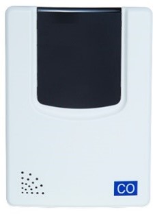
  • A CO sensor is used to detect the level of CO and give an output signal. The number of required sensors is decided based on the size of the area or car park. * All sensors will be wired to the common PLC panel. * Location of CO Sensor: * The distance between the Co sensor and the source of CO is important. The air polluted with hazardous gases have to be in physical contact with the gas sensors. Because carbon monoxide is slightly lighter than air and it may be found with warm rising air Hence, CO Sensor is fitted at a distance of 3 feet to 5 feet from the ground surface

B1

  • Do not place the detector right next to or over a fireplace or flame-producing appliance * Each CO sensor can cover approximately 5,000 to 10,000 sq ft of open space. CO gas will disperse and flow with natural air current and car movement. * Using the average of 7,500 sq ft per sensor and a circular radius of 49 feet, the sensors area coverage could be scaled and placed on the Basement layout to cover the open floor area. Based on the number of CO sensors and the location of the exhaust fans and make-up air handlers. * The most practical mounting location for a CO sensor within a basement area is the side of the support column away from traffic. * CO sensors will be more effective if placed in areas where CO levels are likely to be high. For example, do not place sensors adjacent to the fresh air intake. * Programmable Logic Controller (PLC) panel * All the inputs from the CO sensors are connected to a PLC (Programmable Logic Controller) for proper control functioning. The PLC will provide output signals to the VFD based on the inputs from the sensors. * Variable Frequency Drive (VFD)

B2

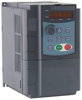
  • A VFD is used to operate a motor at different speeds. This VFD will be controlled by the PLC and will control the exhaust fans. If the CO content is more, the exhaust fan operates at a faster speed. * Exhaust Fans / Fresh Air Fans

B3

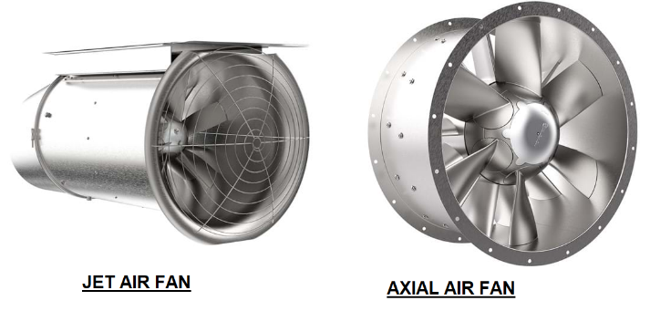
  • The number of required Exhaust / Fresh Air fans will be decided based on the size and shape of the area. The Exhaust Fresh Air Fans are controlled by the VFD. Basically, the Exhaust Fans / Fresh Air Fan have to remove the contaminated air at a fast rate.

(6) WORKING PRINCIPLE AND SYSTEM ARCHITECTURE:

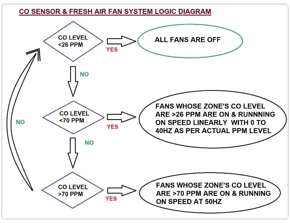
  • A number of CO monitoring sensors are installed at various points of the basement car parking. The number of required sensors is decided based on the size of the area or car parking. * All CO sensors are wired to the common PLC panel to VFD to Exhaust Fan operations. * CO sensors detect various types of smoke, Smoke radicals, and fumes and generates a contr…

Solar Panel Installation Guideline

SOLAR PANEL INSTALLATION GUIDELINE

October 2, 2023 Leave a comment

21.2.1 Solar Photovoltaic Power Generation System (NATIONAL BUILDING CODE 2016) Building Type Plot Size Generation Requirement Residential (Plotted houses) 100 m2 and above 1 kWp or 5% of connected load, whichever is higher Residential (Group housing) All sizes Minimum 5% of connected load Business, educational buildings having connected load of 30 kW and above 500 m2 and above 5 kWp or 5% of connected load, whichever is higher Mercantile, hotels, motels, assembly, industrial and institutional buildings 500 m2 and above for buildings having connected load of: (a) 50 to 1000 kW=10 kWp or 5% of connected load whichever is higher (b) Above 1 000 kW=50 kWp or 5% of connected load whichever is higher

SOALR INSTALLATION -CENTRAL ELECTRICITY AUTHORITY-2023 (12.1) PATH WAY FOR SOLAR SYSTEM Clear pathways of minimum 75cm in width with hand rails for roof access and emergency exit shall be provided for roof top system. there shall be clear pathways, walkways between the rows or columns of solar panels which is necessary for cleaning and maintenance; FENCING ground mounted solar installations shall be protected by fencing or other means not less than 1.8 meter in height so as to prevent unauthorized entry; ISOLATING DEVICE Disconnection switches or circuit breakers provided in combiner boxes to disconnect the photovoltaic system from all other conductors of the system shall be located at a readily accessible location; three phases on the alternating current side, and positive and negative conductor on the direct current side shall be marked and identified with different colours manual disconnection switch to isolate the system from grid and shall be situated outside the alternating current combiner box INVERTER inverter unit for solar photovoltaics shall be installed in the periphery of the building and as near as the solar panel: PROTECTION protection shall be deployed (for both input and output) on site for overload, surge current, surge voltage, short circuit, high temperature, over voltage, under voltage and over frequency, under frequency, reverse polarity and lightning. the solar photovoltaic power plant shall be provided with lightning and over voltage protection by deploying required number of lightning arresters as per the relevant standards;

Guidelines for Installation of Solar Energy System (Government of Kerala-Electrical Inspectorate) SOLAR SYSTEM APPROVAL 10kW and up to and including 30kW : completion report and SLD shall be submitted by the consumer through a competent electricals contractor and sanction for energization shall be obtained from the district office concerned 30kW to 5O0kW: Prior scheme approval and sanction for energization orders shall be obtained from the district office concerned above 500kW :Prior scheme approval and sanction for energization orders shall be obtained from the office of the Chief Electrical Inspector PANEL MOUNTING STRUCTURE Galvanized iron (Gl) or aluminum shall be used for module mounting structures. Be located at a height of at least 2.44 m above the ground level CABLE SIZE Cable size for PV string cable, PV sub-array cable and PV array main cable shall be selected as per section 7.3.7 of IEC 62548/2016. PV CELL PV string connected in parallel shall have matched open circuit voltage within 5% per string to avoid circulating current. (Refer section 5.1.6 of IEC 62548/2016). Solar PV module details such as number of modules, wattage, number of cells, voltage, current etc. shall be verified INVERTER Inverter capacity shall be selected based on the solar PV generation, so that maximum generation can be utilized. Inverter protection settings, installer details and emergency shutdown procedures shall be displayed on site. HARMONIC INJECTION PV system shall not inject DC current greater than 1 percent of the inverter rated output current into the grid. Solar inverters shall be rated for THD of less than 3 percent of power injected into the grid Harmonic current injections from a generating station shall not exceed the limits specified in IEEE 519 The distributed generating resource shall not inject direct current greater than 0.5 % of the full rated output at the interconnection point PARALLELING THE SYSTEM Paralleling device of distributed generation resource shall be capable of withstanding 220 % of the nominal voltage at the interconnection point. VOLTAGE FLUCTUATION Every time the generating station is synchronised to the electricity system, it shall not cause voltage fluctuation greater than ± 5 % at the point of connection The distributed generating resource shall not introduce flicker beyond the limits specified in IEC 61000 EARTHING Up to 5kW solar plants, 2NO’S of earth electrodes are sufficient and LA shall be provided in lightning prone area. Above 5kW and up to 100kW solar plants, 3NO’S of ea…
Quick Reference-Lift / Service Duct / HVAC / Sub Station

QUICK REFERENCE-LIFT / SERVICE DUCT / HVAC / SUB STATION

May 31, 2024 Leave a comment

LIFTS

Model Building-Bye-laws-2016, Ministry of Urban Development, Government of India

Head

Clause

Description

 LIFTS

7.10.a Provision of the lifts shall be made for all multi- storied building having a height of 15.0 m. and above. 7.10. b Grounding switch at ground floor level to enable the fire service to ground the lift car in case of emergency shall also be provided. 7.10.c The lift machine room shall be separate and no other machinery be installed in it.

Lift Enclosure

7.10.1.a Walls of lift enclosures shall have a fire rating of two hours. Lift shafts shall have a vent at the top of area not less than 0.2 sq m. 7.10.1.c Landing door in lift enclosures shall have a fire resistance of not less than one hour. 7.10.1.d The number of lifts in one lift bank shall not exceed four. A wall of two hours fire rating shall separate individual shafts in a bank. 7.10.1.e Lift car door shall have a fire resistance rating of 1 hour. 7.10.1.f For buildings 15.0 m. and above in height, collapsible gates shall not be permitted for lifts and solid doors with fire resistance of at least one hour shall be provided. 7.10.1.g If the lift shaft and lobby is in the core of the building a positive pressure between 25 and 30 pa shall be maintained in the lobby and a possible pressure of 50 pa shall be maintained in the lift shaft. The mechanism for the pressurization shall act automatically with the fire alarm/sprinkler system and it shall be possible to ope

EV CHARGING

EV CHARGING

March 24, 2024 Leave a comment

Central Electricity Authority (Measures relating to Safety and Electric Supply)-2010

Electric Vehicle Charging Stations (Chapter XI-11.7)

Public Charging Stations Private charging at residences offices shall be permitted. Distribution Companies (DISCOMs) may facilitate the same. Public Charging Stations (PCS) shall be a de-licensed activity and any individual/entity is free to set up public charging stations provided that, such stations meet the technical, safety as well as performance standards and protocols laid down below as well as any further norms standards specifications laid down by Ministry of Power and Central Electricity Authority (CEA) from time to time. PROTECTION All electric vehicle charging stations shall be provided with protection against the overload of input supply and output supply fittings. The electric vehicle charging station shall be equipped with a protective device against the uncontrolled reverse power flow from vehicle. Suitable lightning protection system shall be provided for the electric vehicles charging stations as per Indian Standards Code IS/ IEC 62305. A cord extension set or second supply lead shall not be used in addition to the supply lead for the connection of the electric vehicle to the electric vehicle charging point and it shall be so constructed so that it cannot be used as a cord extension set. An adaptor shall not be used to connect a vehicle connector to a vehicle inlet. HEIGHT All electric vehicle charging points shall be installed so that any socket-outlet of supply is at least 800 MM above the finished ground level. AREA The electric vehicle parking place shall be such that the connection on the vehicle when parked for charging shall be within 5 meters from the electric vehicle charging point. Portable socket-outlets are not permitted to be used for electric vehicle charging. D.C Charging A vehicle connector used for Direct Current (D.C.) charging shall be locked on a vehicle inlet if the voltage is higher than 60 V D.C. and the vehicle connector shall not be unlocked (if the locking mechanism is engaged) when hazardous voltage is detected through charging process including after the end of charging and in case of charging system malfunction, a means for safe disconnection shall be provided. The Direct Current (D.C.) electric vehicle charging point shall disconnect supply of electricity to prevent overvoltage at the battery, if output voltage exceeds maximum voltage limit sent by the vehicle. The electric vehicle charging points shall not energize the charging cable when the vehicle connector is unlocked and the voltage at which the vehicle connector unlocks shall be lower than 60V. Earth protection system for charging stations. All Residual current device for the protection of supplies for electric vehicle shall (a) have a residual operating current of not greater than 30 Ma (b) interrupt all live conductors, including the neutral (c) have a performance at least equal to Type A and be in conformity with IS 732-2018. Each electric vehicle charging points shall be supplied individually by a dedicated final sub-circuit protected by an overcurrent protective device complying with IEC 60947-2, IEC 60947-6-2 or the IEC 60269 series and the overcurrent protective device shall be part of a switchboard. All electric vehicle charging stations shall be supplied from a sub-circuit protected by a voltage independent residual current device and also providing personal protection that is compatible with a charging supply for an electric vehicle. All electric vehicle charging stations shall be provided with an earth continuity monitoring system that disconnects the supply in the event that the earthing connection to the vehicle becomes ineffective. A protective earth conductor shall be provided to establish an equipotential connection between the earth terminal of the supply and the conductive parts of the vehicle which shall be of sufficient rating to satisfy the requirements of IEC 60364-5-54. Fire Fighting System in electric vehicle charging stations Enclosure of charging stations shall be made of fire retardant material with self-extinguishing property and free from Halogen. Fire detection, alarm and control system shall be provided as per relevant Indian Standards. Power supply cables used in charging station or charging points shall conform to IEC 62893-1 and its Testing of charging stations All apparatus of charging stations shall have the insulation resistance value as stipulated in the relevant IEC 61851-1. Inspection and periodic assessment of charging stations. Every charging station shall be tested and inspected by the owner or the Electrical Inspector or Chartered Electrical Safety Engineer before energization of charging stations. The owner of the charging station shall ensure that test and inspection of charging…
Electrical Abstract-Gujarat Fire Prevention and Life Safety Regulations, 2023

ELECTRICAL ABSTRACT-GUJARAT FIRE PREVENTION AND LIFE SAFETY REGULATIONS, 2023

February 20, 2024 1 Comment

ELECTRICAL CLAUSE (GUJARAT FIRE PREVENTION AND LIFE SAFETY REGULATIONS, 2023)

Clause

Head

Description

17 /18

Electrical Duct:

Buildings Height more than 15 meters up to 70 meters: Electrical duct should have sealed metal doors with metal frame or fire rated doors at each floor level. Opening of the duct shall be from basement to terrace level. 15.3 / 17 /18 /19

Electrical Installations

Buildings of Height up to 45 meters: Electric cable/wires used shall be of 700 volts grading with Mechanical circuit breaker and earth Leak Circuit Breaker (MCB and ELCB). Buildings of Height more than 15 meters up to 70 meters: Electric cable/wires used shall be of 900 volts grading with Mechanical circuit breaker and earth Leak Circuit Breaker (MCB and ELCB). Buildings of Height more than 15 meters up to 70 meters: Electrical Installations from Fire Safety point of view shall comply with IS-1646. Use of fire resistance cables and wires. 15.31

Electrical Installations

Buildings of Height more than 15 meters up to 70 meters: Separate uninterrupted standalone power supply shall be provided for emergency services, which includes Fire Pump, Sprinkler Pump, Fire Lift, Staircase Lighting. 15.23

Sub-Stations

The sub-station shall have separate fire resisting walls / surroundings and shall necessarily be located at the periphery of the floor having separate access preferably from fire escape staircase. The outside walls, ceiling and floor including doors and windows to the sub-station area shall be of 2 hours fire rating. Oil Filled Equipment at Basement: A sub-station or a switch-station with oil- filled equipment must not be located in the building. When housed inside the building, The transformer shall be of premises by walls/doors/cut outs having Fire Resistance rating of 4 hours. The Sub-Station area needs to be maintained at negative air pressure and area in substation shall not be used as storage/dump areas. Transformer in Building Area: No transformer shall be allowed inside the building. Substation to be provided at rear corner of a building unit after leaving enough open space around the building for firefighting requirements 15.11

Electrical Services:

Back up Supply: Electric supply for fire pump/fire lift shall be provided separately and not get switched off along with the main supply of building. Fire Retardant Sealant: The electric distribution cable/wiring shall be laid in a separate duct. The duct shall be sealed at every floor with non-combustible materials having the same fire resistance as that of the duct. Separate Conduit: Low and medium voltage wiring running in shaft and in false ceiling shall run in separate conduits. Separate Circuit: Separate circuits for firefighting pumps, lifts, staircases, corridor lighting and blowers for pressurizing system shall be provided directly from the main switch gear panel and these circuits shall be laid in separate conduit pipes, so that fire in one circuit will not affect the others. Such circuits shall be protected at origin by an automatic circuit breaker with its no- volt coil removed. Master switches controlling essential service circuits shall be clearly labelled. Electrical Room: An independent and well-ventilated electrical service room shall be provided on the ground level or first basement with direct access from outside or from the corridor for the purpose of termination of electric supply from the licensees’ service and alternative supply cables. Fire Door: The doors provided for the Service Room shall have fire resistance of not less than 2 hours Electrical Room at Basement: If service room is located at the first basement, it should have automatic fire extinguishing system

15.20

Service Ducts/Shafts

Fire Door : Electrical Shafts / Ducts shall have not less than 2 hours fire resistance and for other services shafts/ducts, the fire resistance shall be not less than 1 hour. Fire Retardant Sealant: All such ducts/ shafts shall be properly sealed and fire stopped at all floor levels Opening at Terrace: A vent opening at the top of the service shaft shall be provided having between one – fourth and one half of the area of the shaft. Refuse Cute: Refuse chutes shall have opening at least 1 m above roof level for venting purpose and they shall have an enclosure wall of non-combustible material with fire resistance of not less than 2 hours. They shall not be located within the staircase enclosure or service shafts, or air-conditioning shafts. Inspection panel and doors shall be tight fitting with1 hour fire resistance; the chutes should be as far away as possible from exits. 15.5

Exit Door / Exit Area Illumination

Exit Signage: Exits shall be clearly visible and the route to reach the exits shall be clearly marked and signs posted to guide the o…

Solar Panel Installation Guideline

SOLAR PANEL INSTALLATION GUIDELINE

October 2, 2023 Leave a comment

21.2.1 Solar Photovoltaic Power Generation System (NATIONAL BUILDING CODE 2016) Building Type Plot Size Generation Requirement Residential (Plotted houses) 100 m2 and above 1 kWp or 5% of connected load, whichever is higher Residential (Group housing) All sizes Minimum 5% of connected load Business, educational buildings having connected load of 30 kW and above 500 m2 and above 5 kWp or 5% of connected load, whichever is higher Mercantile, hotels, motels, assembly, industrial and institutional buildings 500 m2 and above for buildings having connected load of: (a) 50 to 1000 kW=10 kWp or 5% of connected load whichever is higher (b) Above 1 000 kW=50 kWp or 5% of connected load whichever is higher

SOALR INSTALLATION -CENTRAL ELECTRICITY AUTHORITY-2023 (12.1) PATH WAY FOR SOLAR SYSTEM Clear pathways of minimum 75cm in width with hand rails for roof access and emergency exit shall be provided for roof top system. there shall be clear pathways, walkways between the rows or columns of solar panels which is necessary for cleaning and maintenance; FENCING ground mounted solar installations shall be protected by fencing or other means not less than 1.8 meter in height so as to prevent unauthorized entry; ISOLATING DEVICE Disconnection switches or circuit breakers provided in combiner boxes to disconnect the photovoltaic system from all other conductors of the system shall be located at a readily accessible location; three phases on the alternating current side, and positive and negative conductor on the direct current side shall be marked and identified with different colours manual disconnection switch to isolate the system from grid and shall be situated outside the alternating current combiner box INVERTER inverter unit for solar photovoltaics shall be installed in the periphery of the building and as near as the solar panel: PROTECTION protection shall be deployed (for both input and output) on site for overload, surge current, surge voltage, short circuit, high temperature, over voltage, under voltage and over frequency, under frequency, reverse polarity and lightning. the solar photovoltaic power plant shall be provided with lightning and over voltage protection by deploying required number of lightning arresters as per the relevant standards;

Guidelines for Installation of Solar Energy System (Government of Kerala-Electrical Inspectorate) SOLAR SYSTEM APPROVAL 10kW and up to and including 30kW : completion report and SLD shall be submitted by the consumer through a competent electricals contractor and sanction for energization shall be obtained from the district office concerned 30kW to 5O0kW: Prior scheme approval and sanction for energization orders shall be obtained from the district office concerned above 500kW :Prior scheme approval and sanction for energization orders shall be obtained from the office of the Chief Electrical Inspector PANEL MOUNTING STRUCTURE Galvanized iron (Gl) or aluminum shall be used for module mounting structures. Be located at a height of at least 2.44 m above the ground level CABLE SIZE Cable size for PV string cable, PV sub-array cable and PV array main cable shall be selected as per section 7.3.7 of IEC 62548/2016. PV CELL PV string connected in parallel shall have matched open circuit voltage within 5% per string to avoid circulating current. (Refer section 5.1.6 of IEC 62548/2016). Solar PV module details such as number of modules, wattage, number of cells, voltage, current etc. shall be verified INVERTER Inverter capacity shall be selected based on the solar PV generation, so that maximum generation can be utilized. Inverter protection settings, installer details and emergency shutdown procedures shall be displayed on site. HARMONIC INJECTION PV system shall not inject DC current greater than 1 percent of the inverter rated output current into the grid. Solar inverters shall be rated for THD of less than 3 percent of power injected into the grid Harmonic current injections from a generating station shall not exceed the limits specified in IEEE 519 The distributed generating resource shall not inject direct current greater than 0.5 % of the full rated output at the interconnection point PARALLELING THE SYSTEM Paralleling device of distributed generation resource shall be capable of withstanding 220 % of the nominal voltage at the interconnection point. VOLTAGE FLUCTUATION Every time the generating station is synchronised to the electricity system, it shall not cause voltage fluctuation greater than ± 5 % at the point of connection The distributed generating resource shall not introduce flicker beyond the limits specified in IEC 61000 EARTHING Up to 5kW solar plants, 2NO’S of earth electrodes are sufficient and LA shall be provided in lightning prone area. Above 5kW and up to 100kW solar plants, 3NO’S of ea…

Sub Station Fence Guideline

SUB STATION FENCE GUIDELINE

September 1, 2023 1 Comment

Indian Electricity Act, 1910 And Indian Electricity -Rules, 1956 RULE 68(b) Fence In the case of outdoor type of sub-station, a metallic fencing of not less than 1.8 meter height shall be erected around the transformer.

BS 1722-10:2019 

Fence Anti-intruder fences in chain link and welded mesh for anti-intruder chain link or welded mesh fences and gates of at least 2.4 meter in height for situations that require a higher level of protection

NEC 110.31 Enclosure for Electrical Installations

Fence A fence shall not be less than 2.1 meter (7 ft) in height or a combination of 1.8 meter (6 ft) or more of fence fabric and a 300 mm (1 ft) or more extension utilizing three or more strands of barbed wire or equivalent.

Rajasthan Rajya Vidyut Prasaran Nigam Limited

Fence Fencing and Gates shall be provided for Switchyard area as per General Electrical Layout Plan. The height of fence post shall be at least 3050 mm.

THE HARYANA BUILDING CODE, 2017

Fence Boundary wall up to the height of 2400mm may be permitted by the Competent Authority in electric sub-stations, transformer stations, industrial buildings (workshops, factories) , institutional buildings (hospitals ), educational buildings (schools, colleges, including hostels and other uses of public utility undertakings and strategically sensitive buildings.

Guide to the Safety, Health and Welfare at Work-IRELAND

Fence The transformer or switchgear is adequately protected either by suitable fencing not less than 2400MM high, or by some other effective means such as high walls or some other effective means for preventing any unauthorized person gaining access to the equipment or to anything connected there to which is used as a conductor unless it is completely enclosed by (i) a metal casing which is connected to earth, or (ii) some other equally suitable non-metal casing.

NATIONAL BUILDING CODE OF INDIA 2016

CLAUSE 4.6 (b)

Enclose any part of the substation which is open to the air, with a fence (earthed efficiently at both ends) or wall not less than 1 800 mm (preferably not less than 2400 mm) in height; to prevent, so far as is reasonably practicable, danger of electric shock or unauthorized access; CLAUSE 5.3.6.10

Electrical installations in a room or cubicle or in an area surrounded by wall fence, access to which is controlled by lock and key shall be considered accessible to authorized persons only. Such installations shall be efficiently protected by fencing not less than 1 800 mm in height or other means so as to prevent access to the electric supply lines and apparatus therein by an undesignated person and the fencing of such area shall be earthed efficiently.

NEC TABLE 110.31. MINIMUM DISTANCE FROM FENCE TO LIVE PARTS

NOMINAL VOLTAGE MINIMUM DISTANCE FROM LIVE PART 1KV TO 13.7KV 3.05 METER 13.8KV TO 23KV 4.57 METER OVER 23KV 5.49 METER

ESKOM TRANSMISSION SUBSTATIONS Table 1: Security and safety fences

Fence Fence Type IP spacing Strain Posts Spacing Security 2.4 Meter high, welded mesh fence 4.0m maximum 40m maximum where distance between corner posts exceed 90m Safety 1.8 Meter high, diamond mesh 4.5m maximum 60m maximum where distance between corner posts exceed 90m

Outdoor Transformer / Panel Fencing as per UGVCL

Fence Height 1600 MM (1500+100 mm) above ground and 450 mm in ground; minimum Width and Length as per site conditions and as decided by EIC (Engineer In-charge). Fencing Gate Fencing gate should have door with two shutters with one Heavy duty S.S. aldrop of size not less than 16 mm Día and 350 mm length. Gate is to be provided as per site conditions. Gate should be suitably stiffened to prevent sagging. 3nos. of Hinges of 100 mm size on each door and shall be of heavy duty S.S. and facilitate of outward 180 degree movement of the gate flaps. Left door of gate should be provided with stopper of 300 mm and Dia. of 10 mm at upper and lower part of fencing with proper locking arrangement. Grade of Material for Fencing Pultruded FRP – UV and Fire Resistant conforming to IS 6746 Bracing Flat SMC molded / FRP Flat 35 x5mm and length 300 mm Vertical Post (Pultruded FRP) The vertical post shall be made out of FRP Pultruded square hollow section of size 50x50x5 mm. Such posts shall be kept at a distance not exceeding 1000 mm and shall be grouted in the ground with c.c. of ratio 1:2:4 in the pit of size 300x300x450 mm Post should be buried in foundation at least 450 mm from ground level. Posts at corners and gate openings may be of different size/shape so as to take care of the fencing requirements Sub frame section FRP Box section of 50 x 25 x 5mm Rails Rails shall be made out of FRP notch bars of 12 mm dia. provided at equal spacing not exceeding200 mm Centre to Centre. The rails are placed horizontally and height of the 1st rail from the ground as well as gap between the rails sh…

Quick Reference -HVAC (Part-1)

QUICK REFERENCE -HVAC (PART-1)

HVAC Power Consumption (IS 1391)

Cooling Capacity (Kcal/Hr) Maximum Power Consumption (KW) 3000 1.65 4S00 2.3 6000 3.1 7500 3.6 9000 4.4 1 kcal/Hr= 1.16278 watt

HVAC Noise Level (IS 1391)

Rated Cooling Capacity (Kcal/Hr) Maximum Noise Level (DBA) Indoor Outdoor 4500 or less 58 68 5000 or more 62 70

Centrifugal Fans (As per CPWD)

Type Characteristics Typical Applications Efficiency (%) Radial High pressure, medium flow, efficiency close to tube-axial fans, power increases continuously Various industrial applications, suitable for dust laden, moist air/ gases 72–79 Forward curved blades Medium pressure, high flow, dip in pressure curve, efficiency higher than radial fans, power rises continuously Low pressure HVAC, packaged units, suitable for clean and dust laden air/ gases 60–65 Backward curved blades High pressure, high flow, High efficiency, power reduces as flow increases beyond point of highest efficiency HVAC, various industrial applications forced draft fans, 79–83 Airfoil type Same as backward curved type, highest efficiency Same as backward curved, but for clean air applications 79–83

Axial Flow Fans (As per CPWD)

Type Characteristics Typical Applications Efficiency (%) Propeller Low pressure, high flow, low efficiency, peak efficiency close to point of free air delivery (zero static pressure) Air-circulation, ventilation, exhausts. 45–50 Tube axial Medium pressure, high flow, higher efficiency than propeller type, dip in pressure-flow curve before peak pressure HVAC, drying ovens, exhaust Systems 67–72 Vane axial High pressure, medium flow, dip in pressure-flow curve, use of guide vanes improves Efficiency exhausts High pressure applications including HVAC systems 78–85

Thickness of sheets for Rectangular Ductwork (As per CPWD)

Longest side (mm) Minimum sheet thickness For GSS For Aluminum 750 mm and below 0.63 mm 0.8 mm 751 mm to 1500 mm 0.8 mm 1 mm 1501 mm to 2250 mm 1 mm 1.5 mm 2251 mm & above 1.25 mm 1.8 mm All ducts shall be fabricated either from Galvanized Sheet Steel (GSS) conforming to IS: 277 or aluminum sheets conforming to IS:737. The steel sheets shall be hot dip galvanized with MAT finish with coating of minimum 120 grams per square meter (GSM) of Zinc, GI sheets shall be lead free, eco friendly and Ro HS compliant

Thickness of sheet for Round Ducts (As per CPWD)

Diameter of duct, mm Thickness of Sheet For GSS For Aluminum 150 to 500 mm 0.63 mm 0.8 mm 501 to 750 mm 0.8 mm 0.8 mm 751 to 1000 mm 0.8 mm 1 mm 1001 to 1250 mm 1 mm 1.5 mm 1251 mm and above 1.25 mm 1.8 mm All sheet metal connections, partitions and plenums required for flow of air through the filters, fans etc. shall be at least 1.25 mm thick galvanized steel sheets, in case of G.I. sheet ducting or 1.8 mm thick aluminum sheet, in case of aluminum sheet ducting and shall be stiffened with 25 mm x 25 mm x 3 mm angle iron braces. Circular ducts, where provided shall be of thickness as specified in IS: 655 as amended up to date. Aluminum ducting shall normally be used for clean room applications, hospitals works and wherever high cleanliness standards are functional requirements

Duct’s Associated Items

Application Duct Width Angle size Flanges Up to 1000 mm 35 mm x 35 mm x 3 mm Flanges 1001 mm to 2250 mm 40 mm x 40 mm x 3 mm Flanges More than 2250 mm 50 mm x 50 mm x 3 mm Bracings Up to 1000 mm 25 mm x 25 mm x 3 mm Bracings More than 1000 mm 40 mm x 40 mm x 3 mm Support angles Up to 1000 mm 40 mm x 40 mm x 3 mm Support angles 1001 mm to 2250 mm 40 mm x 40 mm x 3 mm Support angles More than 2250 mm Size and type of RS section shall be decided in individual cases Hanger rods shall be of mild steel and of at least 10 mm dia for ducts up to 2250 mm size, and 12 mm dia for larger sizes All nuts, bolts and washers shall be zinc plated steel. All rivets shall be galvanized or shall be made of magnesium – aluminum alloy. Self tapping screws shall not be used.

Comparison of the VRF/ VRV systems with the Central Chilled water system (As per CPWD)

Points VRF AC Chilled Water based AC Remarks System Base It is Gas Base System It is Water Base System Peak Power Demand 1.6KW/TR peak. (Efficiency drastically reduces at high ambient) 1.3KW/TR Peak. (IKW/TR<0.6 now for chilling units.) Higher size & cost of Power Supply Capital Equipment like Transformers etc. & thus higher Cu losses in VRF system. Annual Power Consumption 1.15 to 1.20 1 Annually extra expenditure of 15 to 20% in electricity bills in VRF system. Security & Safety of Equipment & System Copper piping on terrace & in building MS piping VRF system equipments/ materials prone to theft & damage by miscreants Terrace Space Almost 80% terrace is used for ODUs & Cu pipe & power cables Only Cooling Towers need to be installed at terrace. Problem of cleaning terrace & loss of water proofing also occurs over time. Water Scarcity No water require…

Quick Reference -HVAC (Part-2)

QUICK REFERENCE -HVAC (PART-2)

A.C Capacity

Ton KW H.P 0.64 2.1 0.8 0.80 2.8 1 1.00 3.7 1.25 1.28 4.6 1.6 1.60 5.6 2 2.00 7.31 2.5 2.56 9.35 3.2 3.20 11.6 4 4.00 14.4 5 4.48 16.7 5.6 6.40 22.1 8 8.00 29.1 10 1TON= 1TON=3000 K.Cal/Hr 1TON=1200 BTU/Hr 1TON=3.516 KW 1TON=1.25 HP (VRV / VRF Only) 1TON=4.7 HP 1TON=12660 KJ/Hr

Split AC Copper Pipe Size (Blue Star)

A.C Capacity Suction Pipe Discharge Pipe (Liquid) Up to 1 Ton 12.7mm (1/2″) 6.4mm (1/4″) 1 To 4 Ton 15.9mm (5/8″) 9.5mm (3/8″) 5 To 6 Ton 19.1mm (3/4″) 9.5mm (3/8″) 7 To 8 Ton 22.2mm (7/8″) 12.7mm (1/2″) 9 To 11 Ton 28.6mm (1 1/8″) 12.7mm (1/2″) 12 To 19 Ton 28.6mm (1 1/8″) 15.9mm (5/8″) 20 To 27Ton 34.9mm (1 3/8″) 19.1mm (3/4″) 28 To 42Ton 41.5mm (1 5/8″) 19.1mm (3/4″) Normal Split A.C Copper Pipe Maximum Length = 15Meter VRV System Copper Pipe Maximum Length = 150Meter

Split AC Copper Pipe Length

A.C Capacity Maximum Pipe Length Maximum Indoor & Outdoor Height Difference 0.5 Ton 15 Meter 5 Meter 0.6 Ton 15 Meter 5 Meter 0.75 Ton 15 Meter 5 Meter 1 Ton 20 Meter 10 Meter 1.5 Ton 25 Meter 10 Meter 2 Ton 25 Meter 10 Meter 2.5 Ton 30 Meter 10 Meter 3 Ton 30 Meter 20 Meter 3.5 Ton 30 Meter 20 Meter 4 Ton 30 Meter 20 Meter

Split AC Copper Pipe Additional Refrigerant Charge

Total Pipe Length 50 Meter 60 Meter 70 Meter Additional Refrigerant None 250 gm (25gm/Meter) 500 gm (25gm/Meter)

Copper Pipe Thickness

Pipe Size Thickness Tube Gauge Type 6.4mm (1/4″) 0.8 mm 21 Soft 9.5mm (3/8″) 0.8 mm 21 Soft 12.7mm (1/2″) 0.8 mm 21 Soft 15.9mm (5/8″) 1 mm 19 Soft 19.1mm (3/4″) 1 mm 19 Soft 22.2mm (7/8″) 1 mm 19 Hard 28.6mm (1 1/8″) 1.2 mm 18 Hard 34.9mm (1 3/8″) 1.2 mm 18 Hard 41.5mm (1 5/8″) 1.3 mm 18 Hard De-Oxidized Copper Tubes (DHP) , Copper 99.9% Soft Copper as per ASTM B68 Hard Copper as per ASTM B75 / ASTM280 / BS 2871

Gas Pressure For any Ton Capacity

Refergerent Suction Pressure (PSI) Discharge Pressure (PSI) Standing Pressure (PSI) M/C ON M/C ON M/C OFF R 22 60 To 70 250To 300 156 R 32 120 490 260 R 134A 35 158 To 199 95 R 290 65 275 To 300 125 R 404A 87 270 To 356 190 R 407C 63 247 To 307 153 R 410A 110 To 120 400 To 500 250 R 417A 65 261 140

Nitrogen Pressure Test

Vacuum

3 Minutes 150 PSI <= 500 Micron for 24 Hours 5 Minutes 325 PSI 24 Hours 500 PSI vacuum < 500 Micron

System Problems

System Problem Discharge Line Pressure Suction Line Pressure Suction Line Temperature Compressor Amp Over Gas Charge High ↑ High ↑ Low ↓ (Ice on Suction Pipe) High ↑ Under Gas Charge Low ↓ Low ↓ High ↑ Low ↓ Capillary Block Low ↓ Low ↓ High ↑ Low ↓ Less Air Flow on Evaporator (Indoor Unit) Low ↓ Low ↓ Low ↓ Low ↓ Less Air Flow on Condenser (Outdoor Unit) High ↑ High ↑ High ↑ High ↑ Dirty Condenser (Outdoor Unit) High ↑ High ↑ High ↑ High ↑ Low Ambient Temperature Low ↓ Low ↓ Low ↓ Low ↓ High Ambient Temperature High ↑ High ↑ High ↑ High ↑ Insuffient Compressor Low ↓ High ↑ High ↑ Low ↓

Insulation Thickness

Refrigerant Pipe Insulation Drain Pipe Insulation 22.22mm To 28.58mm 19mm 25mm / 32mm /40mm 6mm 12.7mm To 19.05mm 13mm / 19mm 6.35mm To 9.2mm 9mm / 13mm

 Referent Pipe Insulation

Pipe Pipe size Insulation Type (EPDM or NBR) Standard conditions 86°F (30°C), < 85% High humidity conditions(a) 86°F (30°C), >85% Liquid Pipe 1/4″ (6.35 mm) To 3/8″ (9.52 mm) 3/8″ (9 mm) 3/8″ (9 mm) 1/2″ (12.70 mm) To 2″ (50.80 mm) 1/2″ (13 mm) 1/2″ (13 mm) Vapor Pipe 1/4″ (6.35 mm) To 7/8″ (22.23) 1/2″ (13 mm) 3/4″ (19 mm)

The distance between the supports of the copper pipes.

Diameter Distance (m) ≤ 20 mm 1 Meter 20 To 40 mm 1.5 Meter ≥ 40 mm 2 Meter

The permitted length and drop difference

Pipe length Max. pipe length <= 240 Meter Equivalent length from the first branch to the farthest indoor unit <= 40 Meter Drop height Drop height between indoor unit and outdoor unit <= 110 Meter Drop height between indoor units <= 30 Meter

Factory Fabricated

Duct Size Gauge of GI sheet 1 – 900 mm 26 901 -1200 mm 24 1201 -1800 mm 22 1801 – 2100 mm 20 2101 – above 18

Site Fabricated

Duct Size Gauge of GI sheet Upto 750mm 24 750mm- 1500 mm 22 1510 mm- 2250 mm 20 above 2250 mm 18

Horizontal Ductwork

Ducts Size Maximum Spacing Area (m2) Diameter less than 0.4 less than 125 mm 2.5 Meter 0.4 to 1 125 to 1000 mm 2 Meter more than 1 more than 1000 mm 1.2 Meter

Vertical Ductwork

Ducts Type Maximum Spacing (Meter) round 3.6 Meter rectangular 3 Meter

Rectangular Duct Sheet Thickness as per CPWD

Longest side (mm) Minimum sheet thickness Galvanized Sheet Steel (GSS) IS: 277 For Aluminum IS:737 750 mm and below 0.63mm (22 Gauge) 0.8mm (20 Gauge) 751 mm to 1500 mm 0.8mm (20 Gauge) 1mm (18 Gauge) 1501 mm to 2250 mm 1mm (18 Gauge) 1.5 mm (15 Gauge) 2251 mm & above 1.25mm (16 Gauge) 1.8 (13 Gauge)

Round Duct Sheet Thickness as per CPWD

Longest side (mm) Minimum sheet thickness Galvanized Sheet Steel (GSS) IS: 277 For Aluminum IS:737 150 mm to 500 mm 0.63mm (22 Gauge) 0.8mm (20 Gauge) 501 mm to …

Thumb Rules-VENTILATION & CEILING FAN

THUMB RULES-VENTILATION & CEILING FAN

Recommended values for air changes (NBC-5.2.2.1) & CPWD

Application Air Change per Hour Assembly rooms 4 to 8 Bakeries 20 to 30 Banks/building societies 4 to 8 Bathrooms 6 to 10 Bedrooms 2 to 4 Billiard rooms 6 to 8 Cafes and coffee bars 10 to 12 Canteens 8 to 12 Cellars 3 to 10 Changing rooms 6 to 10 Churches 1 to 3 Cinemas and theatres 10 to 15 Club rooms 12, Min 12 to 15 Compressor rooms 10 to 12 Conference rooms 8 to 12 Corridors 5 to 10 Dairies 8 to 12 Dance halls 12 Dye works 20 to 30 Electroplating shops 10 to 12 Entrance halls 3 to 5 Factories and work shops 8 to 10 Foundries 15 to 30 Garages 6 to 8 Glass houses 25 to 60 Gymnasium 6 Hair dressing saloon 10 to 15 Hospitals sterilizing 15 to 20 Hospital wards 6 to 8 Hospital domestic 15 to 20 Laboratories 6 to 15 Launderettes 10 to 15 Laundries 10 to 30 Lavatories 6 to 15 Lecture theatres 5 to 8 Libraries 3 to 5 Lift cars 20 Living rooms 3 to 6 Mushroom houses 6 to 10 Offices 6 to 10 Paint shops (not cellulose) 10 to 20 Photo and X-ray dark room 10 to 15 Public house bars 12 Recording control rooms 15 to 25 Recording studios 10 to 12 Restaurants 8 to 12 Schoolrooms 5 to 7 Shops and supermarkets 8 to 15 Shower baths 15 to 20 Stores and warehouses 3 to 6 STP rooms 30 Squash courts 4 Swimming baths 10 to 15 Toilets 6 to 10 Underground vehicle parking 6 Utility rooms 15 to 30 Welding shops 15 to 30 Note: The ventilation rates may be increased by 50 % where heavy smoking occurs or if the room is below the ground.

Recommended values for air changes

Application Air Change per Minute Assembly Hall 7 Auditorium 10 Barber Shop 6 Basement 8 Battery Room 4 Boiler Room 1 Bowling Alley 5 Engine Room 6 Gymnasium 8 Projection Booth 2 Church 15 Factory 6 Laundry 2 Summer Cooling 1 Classroom 6 Forge Room 3 Locker Room 3 Toilet 3 Dance Hall 5 Foundry 4 Machine Shop 8 Transformer Room 1 Department Store 6 Garage 5 Plating Room 3 Warehouse 12 Dry Cleaning 5 General Office 10 Pressing Room 1 Welding Shop 2

TYPE A CEILING FANS (IS-374)

FAN SIZE AIR DELIVERY (m3/min) MAXIMUM INPUT (W) 900 140 42 1050 165 48 1200 215 50 1400 270 60 1500 300 63

Size of Ceiling Fan

Area Suggested Fan Size Up to 9 Square Meters 900mm (36″) Up to 12 Square Meters 1067mm (42″) Up to 18 Square Meters 1200mm (48″) Up to 30 Square Meters 1300mm (52″) Up to 40 Square Meters 1400mm (56″)

Size and Number of Ceiling Fans for Rooms (As per NBC Table-10)

Room Width Room Length Fan Size (mm) /No of Fan 4 Meter 5 Meter 6 Meter 7 Meter 8 Meter 9 Meter 10 Meter 11 Meter 12 Meter 14 Meter 16 Meter 3 Meter 1200/1 1400/1 1500/1 1050/2 1200/2 1400/2 1400/2 1400/2 1200/3 1400/3 1400/3 4 Meter 1200/1 1400/1 1200/2 1200/2 1200/2 1400/2 1400/2 1500/2 1200/3 1400/3 1500/3 5 Meter 1400/1 1400/1 1400/2 1400/2 1400/2 1400/2 1400/2 1500/2 1400/3 1400/3 1500/3 6 Meter 1200/2 1400/2 900/4 1050/4 1200/4 1400/4 1400/4 1500/4 1200/6 1400/6 1500/6 7 Meter 1200/2 1400/2 1050/4 1050/4 1200/4 1400/4 1400/4 1500/4 1200/6 1400/6 1500/6 8 Meter 1200/2 1400/2 1200/4 1200/4 1200/4 1400/4 1400/4 1500/4 1200/6 1400/6 1500/6 9 Meter 1400/2 1400/2 1400/4 1400/4 1400/4 1400/4 1400/4 1500/4 1400/6 1400/6 1500/6 10 Meter 1400/2 1400/2 1400/4 1400/4 1400/4 1400/4 1400/4 1500/4 1400/6 1400/6 1500/6 11 Meter 1500/2 1500/2 1500/4 1500/4 1500/4 1500/4 1500/4 1500/4 1500/6 1500/6 1500/6 12 Meter 1200/3 1400/3 1200/6 1200/6 1200/6 1400/6 1400/6 1500/6 1200/7 1400/9 1400/9 13 Meter 1400/3 1400/3 1200/6 1200/6 1200/6 1400/6 1400/6 1500/6 1400/9 1400/9 1500/9 14 Meter 1400/3 1400/3 1400/6 1400/6 1400/6 1400/6 1400/6 1500/6 1400/9 1400/9 1500/9

Ceiling Fan Criteria (As per NBC)

Capacity of a ceiling fan =55D m3/min ,D= the longer dimension of a room Height of fan blades above the floor = (3H + W)/4, where H is the height of the room, W is the height of work plane. Minimum distance between fan blades and the ceiling =0.3 m.

Size Your Fan for the Room (ENERGY STAR)

Room Size Fan Size Up to 75 sq. ft. 29 To 36 inches or smaller 75 to 144 sq. ft. 36 to 42 inches 144 to 225 sq. ft. 44 to 50 inches 225 to 400 sq. ft. 50 to 54 inches Over 400 Sq. ft 54 To 72 inches multiple fans installed

Minimum Efficacy Levels of Ceiling Fans (ENERGY STAR )

Airflow (CFM) Minimum Efficacy Level (CFM/W) Low At low speed, airflow of 1250 CFM and an efficiency of 155 cfm/W. Medium At medium speed, airflow of 3000 CFM and an efficiency of 100 cfm/W. High At high speed, airflow of 5000 CFM and an efficiency of 75 cfm/W.

Ceiling Fan Rod Extend Length

Ceiling Height Pole Length 8 Feet No Down rod 9 Feet 6 Inches 10 Feet 12 Inches 11 Feet 18 Inches 12 Feet 24 Inches 13 Feet 36 Inches 14 Feet 48 Inches 15 Feet 60 Inches 20 Feet or greater 72 Inches

Ceiling Fan Height Chart

Ceiling Height Distance < 8 Feet Choose a low-profile ceiling fan. 18″ Minimum distance blade to wall. 7′ minimum distance blade to floor. > 9 Feet Choose a ce…

M

Method for Installation of HVAC System (Part-4)

METHOD FOR INSTALLATION OF HVAC SYSTEM (PART-4)

March 1, 2021 1 Comment

HVAC REFRIGERANT PIPE TESTING:

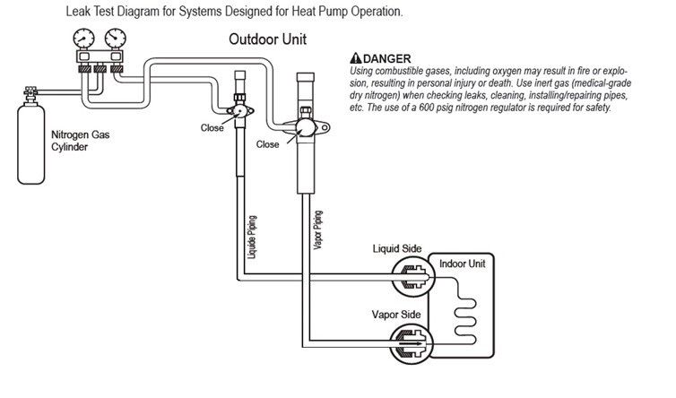
(A) REFRIGERANT PIPING (LEAK CHECK) BY PRESSURE TESTING:

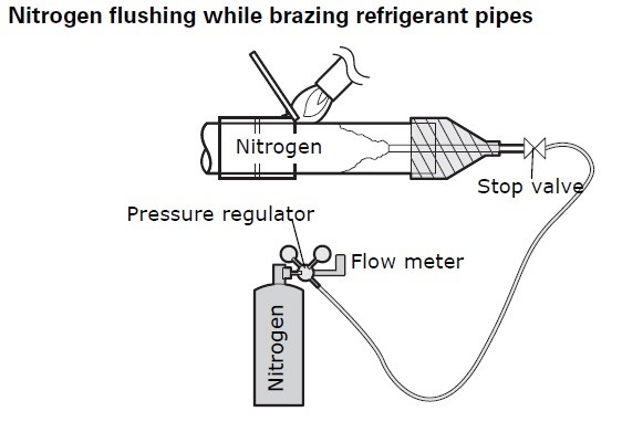
  • Pressure testing helps ensure a leak free system, a critical component to a successful installation. * Max PSI and duration of pressure tests can vary between manufacturers and should be reviewed in the installation manual. * All VRV systems should be pressure tested to 550 PSIG and held for 24 hours. * Pressure testing process: Tighten down stop valves before any pressure testing to prevent nitrogen * From leaking back through condenser and contaminating refrigerant. * Pressure testing shall be done in three (3) steps. * Step 1 – Leak check 3 minutes at 150 PSI * Step 2 – Leak check after 5 minutes at 325 PSI * Step 3 – Leak check after 24 hours at 550 PSI (450 psi for systems with vertical Air Handlers) * After the gauge reading reaches 550 psig, isolate the system by first closing the gauge manifold, then close the nitrogen cylinder valve. * Check the flared and brazed connec­tions for leaks by applying a bubble solution to all joints. * The bubble solution must be a solution designed for refrigerant leak testing. Common soap solution must never be used on refrigerant piping as those contain chemicals that could corrode copper and brass, and cause product malfunction. * If the pressure does NOT drop for 24 hours, the system passes the test. * In this case, the pressure drop of 9.5 psig was due to temperature differences, therefore, there is no leak in the refrigerant piping system. * If the pressure drops and it is not due to ambient conditions, there is a leak and it must be found. Remove the bubble solution with a clean cloth, repair the leak(s), and perform the leak / pressure check again. * After the system has been thoroughly tested and no leaks are found, depressurize by loosening the charging hose connector at the nitro­gen cylinder regulator. When system pressure returns to normal, completely disconnect the charging hose from the cylinder, and release the nitrogen charge from all refrigerant piping. Wipe off any remaining bubble solution with a clean cloth. * Ambient Conditions and the Leak / Pressure Check * If the ambient temperature changed between the times when pressure was applied and when the pressure drop was checked, adjust results by factoring in approximately 0.79 psi for each 1°F / 1°C of temperature difference. * Correction formula: (°F / °C Temperature when pressure was applied – °F / °C Temperature when pressure drop was checked) x 0.79. * Example: When pressure (550 psig) was applied, temperature was 80°F / °C; 24 hours later when pressure drop (540 psig) was checked, temperature was 68°F / °C. * Thus, (80°F / °C – 68°F / °C) x 0.79 = 9.5 psig.

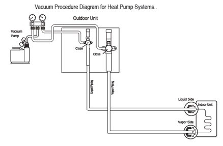
(B) TRIPLE EVACUATION (VACUUM)

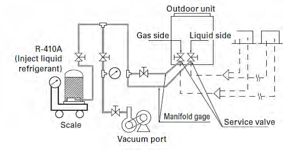
  • Why is a triple evacuation so important instead of a deep vacuum? Because the relationship between pressure and temperature with water. * When the first vacuum is pulled, some of the moisture in the lines boils and evaporates. * However, once it reaches a certain pressure the water will actually freeze and leave small ice crystals in the system. This is why a single deep vacuum is insufficient. * A triple evacuation of all piping should be performed to eliminate moisture in the system: * Do NOT open service valves until the deep vacuum of 500 microns or below has been achieved and the additional charge has been added * If Heat Recovery System connect to all three main refrigeration stop valves at outdoor unit. * Verify that the micron gauge is connected at a point where it can read the system’s pressure at all times during this process, even when the vacuum pump is not running during the hold test. * Evacuation procedures: Evacuation procedures shall be performed as follows: * Step 1- Operate the vacuum pump and evacuate the system to the 2,000 micron level. * Isolate the pump by closing the manifold gauges and the vacuum pump valve, and then watch the micron level. Micron level may rise a bit, but MUST eventually stop rising for fifteen (15) minutes. * If the micron level DOES NOT stop rising, there is a leak, and the leak test must be performed again. If the micron level DOES rise above 2,000 micron, re-open the manifold gauges and the vacuum pump valve and continue evacuation back down to 2,000 micron level. * If the micron level holds at 2,000 micron, Break the vacuum with dry nitrogen to a pressure of 2-3 PSI and hold for 15 minutes (this is to “sweep” moisture from piping). * Step 2- Evacuate to 1,000 micron level. * Isolate the pump by closing the manifold gauges and the vacuum pump valve, and then watch the micron level. Micron level may rise a bit, but MUST eventually stop rising for fifteen (15) minutes. * If the micron level DOES NOT stop rising, there is a leak, and the le…
M

Method for Installation of HVAC System (Part-3)

METHOD FOR INSTALLATION OF HVAC SYSTEM (PART-3)

(C) Y JOINTS

  • Confirm the Y branching piping matches allowable designs from the Installation Manual

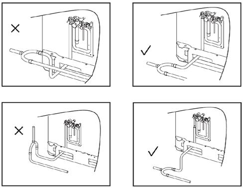
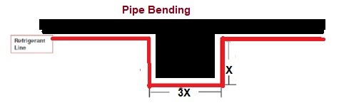
  • Installed with single end of Y Joints always towards outdoor unit. * The branch joint of outdoor side must be installed horizontally. * The branch joint of indoor side can be installed horizontally or vertically. * Y Joints are supported before and after. * “Y” joints are the correct size and match the locations as shown on the Selection Report. * Maintain a minimum distance of 20″ between branching joints, headers, elbows and equipment. * Recommend horizontal runs to be 3 times that of the vertical when traps cannot be avoided

  • Between two branch joints ≥1m * Between branch joints and indoor unit ≥0.5m * From the inlet or outlet of branch joint, there should be straight pipe with length at least 0.5m

(D) COPPER PIPE LENGTH:

The permitted length and drop difference

Pipe length Max. pipe length <= 240 Meter Equivalent length from the first branch to the farthest indoor unit <= 40 Meter Drop height Drop height between indoor unit and outdoor unit <= 110 Meter Drop height between indoor units <= 30 Meter

  • Record the actual liquid pipe length for future reference when charging additional refrigerant.

Split AC Copper Pipe Length

A.C Capacity Maximum Pipe Length Maximum Indoor & Outdoor Height Difference 0.5 Ton 15 Meter 5 Meter 0.6 Ton 15 Meter 5 Meter 0.75 Ton 15 Meter 5 Meter 1 Ton 20 Meter 10 Meter 1.5 Ton 25 Meter 10 Meter 2 Ton 25 Meter 10 Meter 2.5 Ton 30 Meter 10 Meter 3 Ton 30 Meter 20 Meter 3.5 Ton 30 Meter 20 Meter 4 Ton 30 Meter 20 Meter

(E) DRAIN PIPE

  • Water leakage test * Check leakage of water pipe After finished installation of drainage pipe, filled the pipe with water, * Waiting for 24 hours to check whether there’s any leakage. * Check leakage from the indoor unit * Charge water from the check hole of indoor unit to check whether the water can be exhausted smoothly or not

Size of Drain Pipe

Condensate water volume : V (L/h)=Indoor Unit (HP)x2 I.D (mm) Thickness (mm) V ≤ 14 Φ 25 3 14 < V ≤ 88 Φ 30 3.5 88 < V ≤ 175 Φ 40 4 175 < V ≤ 334 Φ 50 4.5 334 < V Φ 80 6 *If Slop is <1% than select next higher Size of Drain Pipe

(F) INSULATION OF REFRIGERANT PIPE & DRAIN PIPE

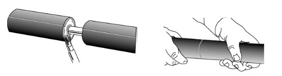
  • The slip-on method of installation is used for insulation on new refrigeration piping * The inside of the insulation is coated with a powdered lubricant, making it easy to slip the insulation over the pipe. * Small amounts of powdered lubricant may enter the open ends of pipe or tubing. This dust must be kept out of refrigeration systems. Plug the open ends of pipe before slipping on the insulation. * Apply insulation only when the pipes are clean, dry, and unheated or uncooled. The surface to be insulated must be free of rust. * Never stretch insulation when sealing the joints. It is better to compress it slightly. Use pieces of insulation that are at least as long as the section of pipe to be insulated. * Always use the insulation that is properly sized for the pipe it is to cover. Do not stretch it over the pipe. * Do not crowd insulation-covered pipes. Space pipes far enough apart to allow for the free circulation of air. Air movement is an extra safeguard against surface condensation of cold pipes, especially under hot, humid conditions.

  • All piping insulation must be properly sealed to minimize heat loss and control condensation. On cold lines, open pipe insulation joints may allow the formation of condensation, increasing the potential for or contributing to possible pipe or tubing corrosion. Seal insulation joints * Do not compress piping insulation at joists, studs, columns, ducts, hangers, etc. This is important because the insulation will lose thermal efficiency where it is compressed. On cold systems, surface condensation may occur where insulation is compressed * Apply a coating of an approved contact-type adhesive to both butt ends to be joined.

  • Before butting the ends together, allow the adhesive to set until it is dry to the touch but still tacky under slight pressure. Join the surfaces. * Cut open the inside wall of the elbow, taking care not to damage the opposite wall. The slit-open elbow should slip over the fitting. Apply adhesive to the seam (not to the butt ends), allow to tack dry, and fit over the fitting. Press the seams together working from the ends toward the center of the elbow.

M

Method for Installation of HVAC System (Part-2)

METHOD FOR INSTALLATION OF HVAC SYSTEM (PART-2)

INDOOR UNIT INSTALLATION:

(A) HIGH WALL UNIT:

  • The installation of the split air conditioners is a crucial job. If the installation is done accurately air conditioner will give optimum cooling, but if it is not done properly we won’t get the desired cooling effect. A poor installations also leads to frequent maintenance problems. * Several factors have to consider during the installation of split air conditioner. * Strength of wall to hold the AC * The indoor unit of split AC must be installed on a wall strong enough to hold the unit’s weight. * Proper spacing between wall and AC unit * The indoor unit of split AC requires at least 15 cm of open space surrounding its top and sides for proper air flow. * Appropriate installation height from ground * Mount the indoor unit of split AC at a height of 7 to 8 feet above the ground for adequate cooling inside the room * Correct tilt angle of indoor unit * While fixing the aluminum bracket on wall make sure that the bracket is given a slight tilt angle, so that the indoor unit of split AC, when fitted is also at a slight angle to enable unrestricted flow of the condensed water from the drain pipe.

(B) CASSATE TYPE:

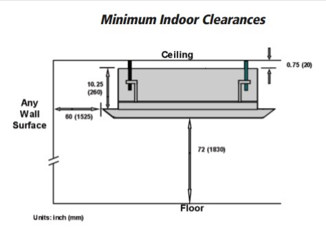
  • Air inlet and outlet should be clear of obstructions, ensuring proper airflow throughout the room. * Condensate can be easily and safely drained. * A structure strong enough to withstand four 4 times the full weight and vibration of the unit. * Filter can be easily accessed for cleaning. * Leave enough free space to allow access for routine maintenance. * Do not install in a laundry room or by a swimming pool due to chemical sorrowing cassette coil.

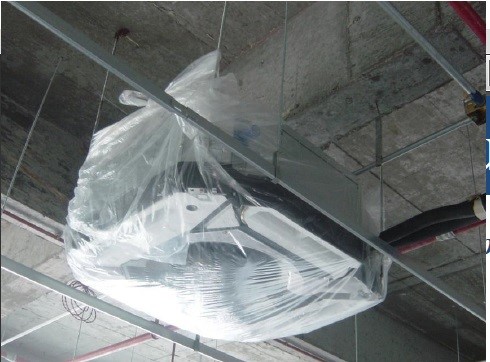
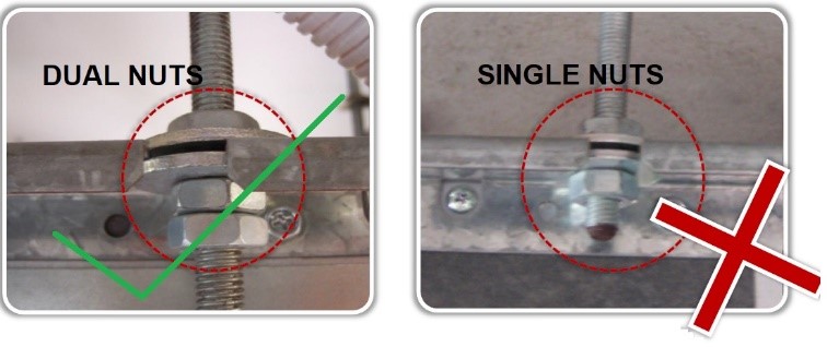
  • Indoor Unit Hanger Mounting Depending on the type of ceiling, attach the threaded hanger bolts securely to the support stud. Before lifting the indoor unit to the installation location, insert the upper nuts, flat washers (with insulation), flat washers (without insulation), lower nuts and double locking nuts on the threaded hanger bolts. * Lift the Ceiling Cassette main body to the threaded hanger bolts. Insert the unit mounting brackets between washers and then fasten it securely. * Pack the indoor unit with plastic bag after hoisting to protect them from dust entering.

LOUVERS:.

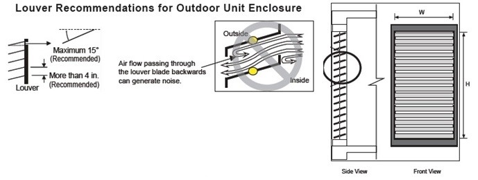
  • Allow for ventilation intake and exhaust air based on maximum outdoor unit fan capacity. * Select the size, type and orientation of architectural louvers with adequate “net free area” face velocity to ensure the total external static pressure from the outdoor unit fan does not exceed design limitations. * No obstructions must be placed in front of the louver that could hamper the free flow (throw) of air. * Roof top openings and / or discharge and supply louvers must be equipped with screens to prevent bird and insect infiltration. * Louver Angle is not more than 15 Deg Horizontally * Space between Louvers is not more than 4 inch * If louver open rate is too small it will create noise from louver blade vibrations. Insufficient air flow exchange creates drop in outdoor unit performance and may create air conditioner stop operating.

REFRIGERANT & DRAIN PIPE INSTALLATION WORK:

(A) PIPE SUPPORT:

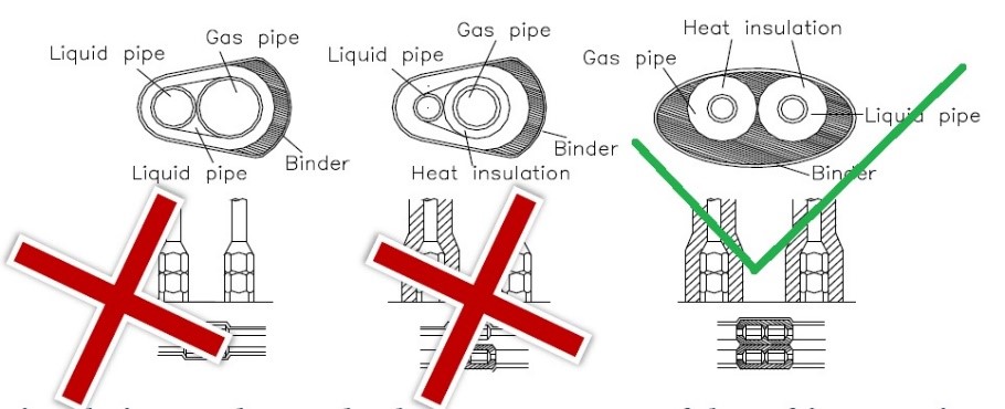
  • A properly installed pipe system will have sufficient supports to avoid pipes from sagging during the life of the system. * Sag­ging pipes become oil traps that lead to equipment malfunction. * Pipe supports must never touch the pipe wall; supports shall be installed outside (around) the primary pipe insulation jacket. Insulate the pipe first because pipe supports shall be in­stalled outside (around) the primary pipe insulation jacket. * Field provided pipe supports must be designed to meet local codes. If allowed by code, use fiber straps or split-ring hangers suspended from the ceiling on all-thread rods (fiber straps or split ring hangers can be used as long as they do not compress the pipe insulation). Place a second layer of insulation over the pipe insulation jacket to prevent chafing and compression of the primary insulation in the confines of the support clamp. * As necessary, place supports closer for segments where potential sagging could occur. Maximum spacing of pipe supports shall meet local codes. If local codes do not specify pipe support spacing, pipe shall be supported: * Wherever the pipe changes direction, place a hanger within twelve 12 inches on one side and within twelve 12 to 19 inches of the bend on the other side. Support piping at indoor units, Y-branch, and Header fittings * Supports must be strong enough. The supports should be full thread booms, and their diameters should be ≥ 10mm. * Dual nuts should be adopted t…
M

Method for Installation of HVAC System (Part-1)

METHOD FOR INSTALLATION OF HVAC SYSTEM (PART-1)

PURPOSE:

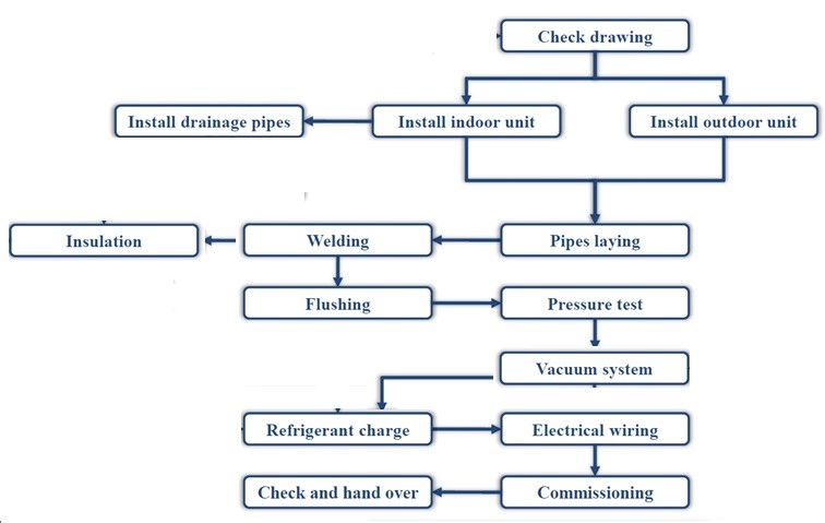
  • This method explains the Procedures or sequence of activity for safely and efficiently installation and Testing of Refrigerant Pipes , Drain Pipes ,Indoor and Out Door Unit of HVAC System as per standard Practice and Code.

GENERAL EQUIPMENT & TOOLS:

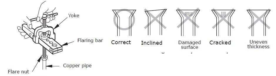
  • The equipment that will be engaged for Installation of Cable works will be * Lifting crane , Transportation vehicle, Fork Lift * Winches, Pulling Rope , Welding machine * Lubricant (Soap based, wax based), Cleaning agent (CRP) * Copper pipe Flaring tools * Vacuum Pump, * Brazing Torch , Brazing Rod , Oxy-Acetylene Brazing Kit ,Wire Brush * Nitrogen Cylinders , Soldering Tools * Crimping tool, Drilling Machine with various Bits , Grinding Machine , Cutting Machine * Electrical Tool Box, Cable Cutter, Screwdriver, Pliers, Spanner. * Ladder , Scaffolding / Mobile scaffold * Nylon rope, Marker , Leveling device , Tape measure * Removable Barricades , Portable Lights * Testing Equipment for System * Multi meter ,Clamp Meter * Refrigerant / Nitrogen cylinder, * Vacuum Gauge

STORAGE & MATERIAL HANDLING:

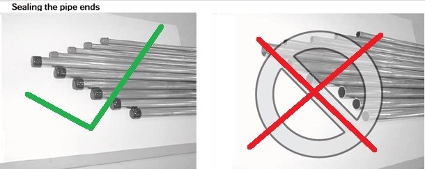
  • The storage area must be free from dust and Water leakages / seepages. * Manufacturer recommendation shall always be followed in loading/unloading and storing of Material. * Material and its accessories shall be unloaded handle with care in designated area of the Store (Do not directly drop to Ground) to avoid any damages. * Materials shall be stored in a dry place which is free from water or from weather effects and protection should be given to the material by means of covering the material with Tarpaulin sheet. * The Material will be stacked / unload in the site store on a proper stand on wooden loft on a flat surface at a sufficient height from Ground. * The A/C Units should be kept on the wooden platform and covering with polythene to protected from any dust or mechanical damages * For storing the copper pipes: * If pipes will be used soon, nozzle should be sealed by plastic bag or tape. * If pipes will be stored for a long time, the pipes should be charged into 0.2 to 0.5MPa Nitrogen and the nozzle should be sealed by welding.

INSPECTION OF MATERIALS:

  • Check The Material according to its Type, Size, Make * Physical Damages Inspection: * Damage on Pipes and Units. * Damage on insulation of Cable * In case of any damages observed during inspection, the Material shall be returned to the supplier for replacement.

 INSTALLATION OF OUTDOOR UNITS :

 (A) TRANSPORTING / LIFTING THE OUTDOOR UNIT

  • Use appropriate moving equipment to transport outdoor Unit, ensure the equipment is capable of supporting the weights. When lifting the unit, use lifting straps and place around the unit. * Always lift the unit using appropriate size of lifting straps rated to carry the unit weight and long enough to maintain a maximum of a 40° angle as shown. * When moving / adjusting the placement of the outdoor unit, always hold the unit by the corners. Moving the outdoor unit using the side intake holes on the frame may damage the frame. * Consider the unit’s center of gravity before lifting. Hoist the unit with the center of gravity centered among the lifting straps. There is a risk of the product falling and causing physical injury. * Lift the outdoor unit from the base at specified locations. Support the outdoor unit at a minimum of six points to avoid slippage from the rigging apparatus. * Do not lay the unit on its side and do not slant the unit more than 30 degrees.

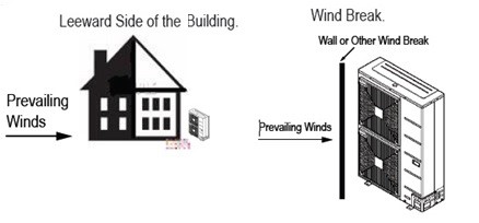
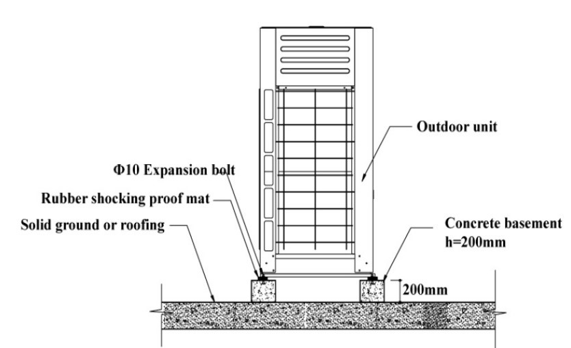
  • On a supporting structure that can bear the weight of the outdoor unit. The supporting structure can be a base on the ground, on a waterproof roof, or in a pit. With sufficient clearances around the unit for service and repairs. In a well-ventilated location. Away from strong wind. * Away from direct exposure to rain or snow. Where there is no risk of flammable vapor leakage. Where there is no exposure to salt, machine oil, sulfide gas, or corrosive environmental conditions.

(B) SELECTING THE BEST LOCATION FOR THE OUTDOOR UNIT(S)

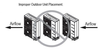
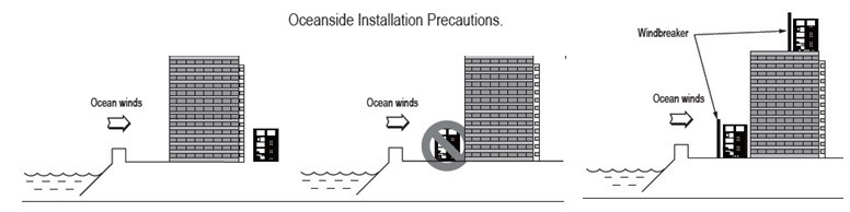
  • Don’ts: * Do not install the unit in an area where combustible gas may generate, flow, stagnate, or leak. These conditions can cause a fire. * Do not install the unit in a location where acidic solution and spray (sulfur) are often used or in environments where oil, steam, or sulfuric gas are present. * A location that allows for optimum air flow and is easily accessible for inspection, maintenance, and Where piping between the outdoor unit and indoor unit(s) / heat recovery units are within allowable Limits. * Avoid placing the outdoor unit in a low-lying area where water could accumulate. * If the outdoor unit is installed in a highly humid environment (near an ocean, lake, etc.), ensure that the…