Site logo
Electrical Engineering Academy
J

Selection of Various Types of UPS (Part-2)

SELECTION OF VARIOUS TYPES OF UPS (PART-2)

(2) LINE-INTER ACTIVE UPS:

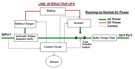
  • Working Principle of Line Interactive UPS is same as OFF Line/ stand UPS. It connected directly from mains, switching to battery (via the inverter) in mains Power cut condition. * The designing of line interactive UPS is same as OFF Line UPS in addition the design Line Interactive generally includes an automatic voltage regulator (AVR) or a tap-changing transformer. This enhances the regulation of voltage by regulating transformer taps as the input voltage differs. * The main difference between an off-line and a line-interactive UPS is that a line-interactive UPS in the stand-by mode has active voltage regulation. * Voltage regulation is a significant feature when the conditions of a low voltage exist, otherwise the UPS would transfer to battery and then finally to the load. The usage of more common battery can cause early battery failure. * It typically uses either a Ferro resonant transformer or a buck-boost transformer. Both helps to reduce the frequency of transfers to battery, slightly improving efficiency and reducing battery wear. * Ferro resonant designs also offer power conditioning and tight voltage regulation, as well as an energy store that can maintain uninterrupted power supply output while the inverter switches on.

Circuit Diagram:

1

Working Function:

  • Normal Condition: * In Normal Power Condition, power supply will continuously provide to Load with some filtering and voltage regulation circuit. * During normal operation, the Line Interactive UPS takes utility power and passes it through a transformer with various tap selections on the output. When utility power is high, the Line Interactive UPS selects a tap to lower (buck) the output voltage. Similarly, when the utility voltage is low, the UPS selects a tap to increase (boost) the output voltage. * In Normal Condition Battery is charged continuous charge through Battery Charger * Battery charger convert AC power to DC Power and this DC Power charged Battery. * Power outage Condition: * When utility power fails, the device will start its internal inverter Circuit by Mechanical Switch. * Mechanically transfer Switch Transfer from utility power to Battery Power, inverter output. * This transfer can take as 2 to 4 ms.

 Advantage:

  • small Size * Low cost * High Efficiency (because less power conversion is when AC input is present). * Sine Way Output. * Battery life is good compared to OFF Line UPS. * Voltage regulation is fair (more than OFF Line UPS but Less than ON Line UPS) * EMI/RFI/Noise Rejection is good. * Change over Time is 2 to 4 Milliseconds. * Lower electricity consumption (less costly to operate). * Higher reliability (Lower component count and lower operating temperatures).

 Disadvantage:

  • No isolation between main supply and load * Higher Heat Output * More Expensive * Problematic with power factor corrected loads.

Applications:

  • For small business. * IT Racks, Network Switches, Medical Instrument System where data loss is a serious problem. * The line interactive UPS may not be the appropriate choice for installations where AC power is unstable or highly distorted, because battery power will be used too often to keep the UPS output within specifications.

 Capacity:

  • UPS in the range of 500VA to 5kVA power.

 (3) ON LINE UPS/ DOUBLE CONVERSION UPS

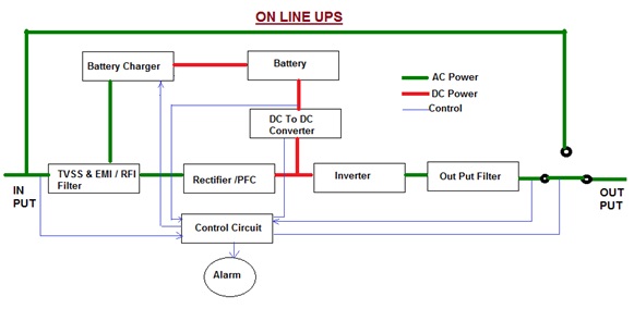
  • It is truly uninterrupted power system (UPS) provide continuous power to load in any condition. * Online UPS sometimes called “double conversion” UPS. * Today most users with highly-critical loads are choose online UPS .It is used to protect sensitive equipment and data from mains problems at all times with any extra cost. * This UPS have no power transfer switches and therefore no transfer time is existed under the mains power failure. Thus this is truly an uninterrupted system. * In Online UPS to maintain the charge of the battery, a battery charging unit is continuously powered from the AC mains. * Online UPSs are often called ‘double conversion’ types because incoming power is Firstly converted once AC to DC for the battery and then back Secondly Converter DC to AC before reaching the load which is therefore well-insulated from the mains like an electrical firewall between the incoming power and sensitive electronic equipments. It also control of the output voltage and frequency regardless of the input voltage and frequency. * The online UPS continuously filters power through the battery before sending it to your computer. * By contrast, online UPS systems draw power through the power conditioning and charging components during normal operation, so the load always receives conditioned power rather than raw mains.

 Circuit Diagram:

1

Working Function:

  • The designing of this UPS is similar to the Standby UPS, excluding that the primary power source is the inverter instead of the AC …
Internal Electrical Work Abstract of CPWD

INTERNAL ELECTRICAL WORK -ABSTRACT OF CPWD

Circuits:

Topic Abstracts Lighting Circuit Per Circuit Not more than 10 Points of Lighting or Total 800Watt which is less Power Circuit For Residential Per Circuit Less than 2 No of 5A/15A Plug Socket Power Circuit For Non Residential Per Circuit Less than 1 No of 5A/15A Plug Socket Plug Socket In Residential wiring ,wiring of Socket outlet shall be done by copper Cable only Min Size of Wire For Lighting Circuit Smallest size of conductor shall be 1.5 Sq.mm Min Size of Wire For Power Circuit Smallest size of conductor shall be 4 Sq.mm

Plug Socket

Plug Socket 5A/6A or 15A/16A Socket shall be installed at following heights: =For Non Residential building 23cm above floor

=For Kitchen 23cm above Platform. 

=For Bathroom not Socket is provided in bathroom MCB/IC will be 2.1 mt from fixed appliance and at least 1 mt away from Shower

Switch Board / D.B

Operating Rod Operating Rod/Handle of Distribution Board at the height of min 2mt D.B Clearance Clear Distance in front of Switch Board/D.B shall be min 1 mt. D.B Clearance If there may be bare connection at back of Switch Board than space behind S/W shall be either less than 20cm or more than 75cm D.B Clearance No fuse Body shall be mounted within 2.5 com edge of D.B or Panel D.B Clearance Clearance between 2.5 cm is maintained between opposite polarity Switch Box Switch Box or Regular Box shall be mounted normally 1.25 mt from floor level.

Fan Hook

Fan Hook For Fan Hook in concrete roof 12mm dia MS Rod in ‘U’ Shape, horizontally Leg at Top at least 19 cm on either side.

Connection between adjustment Building (Out House, Garages)

Safety Clearance If the distance with adjustment building is less than 3 mt and there is no any Road interval than GI pipe of suitable size shall be installed. This pipe shall be exposed on wall at height of not less than 2.5 mt. Safety Clearance If the distance with adjustment building is more than 3 mt and there is any Road interval than GI pipe of suitable size shall be installed. This pipe shall be exposed on wall at height of not less than 4 mt.

Conduit

Metallic Conduit Shall be used for Industrial wiring, Heavy mechanical Stress, shall be ISI marked, The Thickness shall not be less than 1.6mm(16SWG) for conduits up to 32mm Dia and not less than 2mm (14SWG) for conduit above 32mm Dia. Metallic Conduit No steel conduit less than 20 mm Diameter shall be used. Metallic Conduit For rigid Conduit IS:2509/IS:3419 and For Flexible Conduit IS:6946. Metallic Accessories All Metallic conduit accessories shall be threaded type (Not pin grip, clamp grip) Metallic Accessories Saddle for surface conduit work on wall shall not less than 0.55mm(24 gauge) for conduit up to 25mm Dia not less than 0.9mm (20 gauge) for larger Dia Metallic Outlets Fore Cast Boxes:

Wall thickness shall be at least 3mm.

For Welded mild Steel Box:

Wall thickness shall not be less than 1.2mm (18 gauge) for Boxes up to size 20cmX30cm. Above This size 1.6mm(16guage)thick MS Boxes shall be used.

Metallic Outlets Clear depth of Out less Box shall not be less than 60mm.

This will be increased as per mounting of Fan regulator

Bends in Conduits Bending radius not less than 7.5 cm Fixating Conduits on Surface Conduits shall be fixed by saddles not less than 1mt interval but in case of coupler/Bends in either side of saddles, The saddle shall be fitted 30 cm from fitting. Non Metallic Accessories Normally grip Type. Non Metallic Outlet(PVC Box) PVC Box IS:5133(PartII) thickness not less than 2mm,Clear depth of PVC Boxes not less than 60mm. Non Metallic Surface Conduit Conduits shall be fixed by saddles not less than 60cm interval but in case of coupler/Bends in either side of saddles, The saddle shall be fitted 15 cm from fitting.

Junction Box

Junction Box Depth of Junction Box shall be min 65mm as per IS: 2667.

Fish Wire

Fish Wire GI fish wire of 1.6mm/1.2mm (16SWG) shall be used.

Bus bar

Bus bar Busbar shall be 100A,200A,300A,400A,500A,600A,800A Bus bar The Cross-section area of Bus bar shall be same as Phase Bus bar (Up to 200A) for higher Capacity Neutral Bus bar must be not less than half cross section areas of Phase Bus bar. Bus bar Bus bar shall be suitably installed with PVC sleeve/Tap. Bus bar Bus bar Chamber shall be fabricated with MS angle for Frame work and sheet steel of thickness not less than 1.5mm. Bus bar Minimum clearance between phase to earth shall be 26mm and phase to phase shall be 32mm.

Bus bar Trucking

Bus bar Trucking Bus bar Trucking are generally used for interconnection between T/C over 500KVA/D.G set over 500KVA and their switch Board Panel. Bus bar Trucking Bus bar Trucking enclosure sheet steel of min 2mm thickness

Earthing

Earthing Type of earthling are Pipe earthling/Plate earthling/Strip earthling. Earthing Length of Buried strip shall not be less than 15mt. Earthing Two copper …

Electrical Abstract-National Building Code (NBC)

ELECTRICAL ABSTRACT- NBC- (PART-2)

LUMINOUS EFFICACY, LUMEN MAINTENANCE AND COLOR RENDITION (TABLE-8) NBC

Light Source Wattage Efficacy (lm/W ) Average Life Maintenance Color Rendition Incandescent lamps 15 to 200 12 to 20 500 to 1000 Fair to good Very good Tungsten halogen 300 to 1500 20 to 27 200 to 2000 Good to very good Very good Standard fluorescent lamps 20 to 80 55 to 65 5000 Fair to good Good Compact fluorescent lamps (CFL) 5 to 40 60 to 70 7500 Good Good to very good Slim line fluorescent 18 to 58 57 to 67 5000 Fair to good Good High pressure mercury vapor lamps 60 to 1000 50 to 65 5000 Very low to fair Federate Blended – light lamps 160 to 250 20 to 30 5000 Low to fair Federate High pressure sodium vapor lamps 50 to 1000 90 to 125 10000 to 15000 Fair to good Low to good Metal halide lamps 35 to 2000 80 to 95 4000 to 10000 Very low Very good Low pressure sodium 10 to 180 100 to 200 10000 to 20000 Good to very good Poor LED 0.5 to 2.0 60 to 100 10000 Very good Good for white LED

APPROXIMATE CABLE CURRENT CAPACITY

Cable Size Current Capacity MCB Size 1.5 Sq.mm 7.5 To 16 A 8A 2.5 Sq.mm 16 To 22 A 15A 4 Sq.mm 22 To 30 A 20A 6 Sq.mm 39 To 39 A 30A 10 Sq.mm 39 To 54A 40A 16 Sq.mm 54 To 72A 60A 25 Sq.mm 72 To 93A 80A 50 Sq.mm 117 To 147A 125A 70 Sq.mm 147 To 180A 150A 95 Sq.mm 180 To 216A 200A 120 Sq.mm 216 To 250A 225A 150 Sq.mm 250 To 287A 275A 185 Sq.mm 287 To 334A 300A 240 Sq.mm 334 To 400A 350A

REQUIREMENTS FOR PHYSICAL PROTECTION OF UNDERGROUND CABLES (AS PER NBC)

Protective Element Specifications Bricks (a) 100 mm minimum width (b) 25 mm thick (c) sand cushioning 100 mm and sand cover 100 mm Concrete slabs At least 50 mm thick Plastic slabs (polymeric cover strips) Fiber reinforced plastic depending on properties and has to be matched with the protective cushioning and cover PVC conduit or PVC pipe or stoneware pipe or Hume pipe The pipe diameter should be such so that the cable is able to easily slip down the pipe Galvanized pipe The pipe diameter should be such so that the cable is able to easily slip down the pipe The Trench : The trench shall be back filled to cover the cable initially by 200 mm of sand fill; and then a plastic marker strip hall be put over the full length of cable in the trench. The Marker Signs: The marker signs shall be provided where any cable enters or leaves a building. This will identify that there is a cable located underground near the building. The trench shall then be completely filled. If the cables rise above ground to enter a building or other structure, a mechanical protection such as a GI pipe or PVC pipe for the cable from the trench depth to a height of 2.0 m above ground shall be provided.

AREA REQUIRED FOR GENERATOR IN ELECTRIC SUBSTATION (AS PER NBC)

Capacity kVA Area m2 Clear Height below the Soffit of the Beam m 25 56 3.6 48 56 3.6 100 65 3.6 150 72 3.6 248 100 4.2 350 100 4.2 480 100 4.2 600 110 4.6 800 120 4.6 1010 120 6.5 1250 120 6.5 1600 150 6.5 2000 150 6.5

LOW VOLTAGE CABLING FOR BUILDING (AS PER NBC)

Low Voltage Cable Cables/wires, such as fiber optic cable, co-axial cable, etc. These shall be laid at least at a distance of 300 mm from any power wire or cable. The distance may be reduced only by using completely closed earthed metal trucking with metal separations for various kind of cable. Special care shall be taken to ensure that the conduit runs and wiring are laid properly for low voltage signal to flow through it. The power cable and the signal or data cable may run together under floor and near the equipment. However, separation may be required from the insulation aspect, if the signal cable is running close to an un-insulated conductor carrying power at high voltage. All types of signal cables are required to have insulation level for withstanding 2 kV impulse voltages even if they are meant for service at low voltage. Conduit Color Scheme Power conduit=Black Security conduit=Blue Fire alarm conduit=Red Low voltage conduit=Brown UPS conduit Green

SUB STATION GUIDELINE (AS PER NBC)

Substation Location Location of substation in the basement should be avoided, as far as possible. If there is only one basement in a building, the substation/switch room shall not be provided in the basement and the floor level of the substation shall not be lowest point of the basement. Substation shall not be located immediately above or below plumbing water tanks or sewage treatment plant (STP) water tanks at the same location Substation Door/Shutter All door openings from substation, electrical rooms, etc, should open outwards Vertical shutters (like rolling shutters) may also be acceptable provided they are combined with a single leaf door opening outwards for exit in case of emergency For large substation room/electrical room having multiple equipment, two or more doors shall be provided which shall be remotely located from each other No services…

Electrical Abstract -National Electrical Code (NEC)

ELECTRICAL ABSTRACT-NATIONAL ELECTRICAL CODE-NEC

Capacitor Bank for Power Supply Voltage System Voltage Minimum rating of capacitor bank 3.3 KV , 6.6KV 75 Kvar 11 KV 200 Kvar 22 KV 400 Kvar 33 KV 600 Kvar

Capacities of PVC conduits Nominal conductor Size mm 16 mm 20 mm 25 mm 32 mm Number of Cables (maximum) 1.0 6 5 19 30 1.5 5 4 15 24 2.5 3 3 11 17 4 2 2 8 13 6 2 – 6 10 10 – – 4 6 16 – – 3 4 25 – – 2 3 35 – – – 2

System Highest and Lower Voltage Ref: NEC(India) :2011 System Voltage Highest Voltage Lowest Voltage 240 V 264 V 216 V 415 V 457 V 374 V 3.3 kV 3.6 kV 3.0 kV 6.6 kV 7.2 kV 6.0 kV 11 kV 12 kV 10 kV 22 kV 24 kV 20 kV 33 kV 36 kV 30 kV 66 kV 72.5 kV 60 kV 66 kV 72.5 kV 60 kV 132 kV 145 kV 120 kV 220 kV 245 kV 200 kV 400 kV 420 kV 380 kV

Number of Points for Dwelling Unit Ref: NEC(India) :2011 No. Description Area for the Main Dwelling Unit (m2) 35 mm2 45 mm2 55 mm2 85 mm2 140 mm2 1 Light points 7 No 8 No 10 No 12 No 17 No 2 Ceiling fans Pont 2 No 3 No 4 No 5 No 7 No 3 Ceiling fans No’s 2 No 2 No 3 No 4 No 5 No 4 6A Socket outlets 2 No 3 No 4No 5 No 7 No 5 16A Socket outlets – 1 No 2 No 3 No 4No 6 Call-bell (buzzer) – – 1 No 1 No 1 No

Recommended Schedule of Socket-Outlets Ref: NEC(India) :2011 Description Number of Socket 6A Socket 16A Socket Bedroom 2 1 Living room 2 2 Kitchen 1 2 Dining room 2 1 Garage 1 1 For refrigerator – 1 For air-conditioner – 1 for each Verandah 1 per 10mter2 1 Bathroom 1 1

Power requirements of the building Ref: NEC(India) :2011 Part of ElectricalInstallation Part of the Total Power Requirement in % DiversityFactor Ventilation, heating (air-conditioning) 45% 1.0 Power plant (drives) 52% 0.65 Lighting 30% 0.95 Lifts 20% 1.0 Kitchen 10% 0.6 Laundry 5% 0.6

Lift Car Speed Ref: NEC(India) :2011 Occupancy No. of Floors Served Car Speed m/s Office building 4 to 5 0.5 to 0.75 m/sec Office building 6 to 12 0.75 to 1.5 m/sec Shops and departmental stores 13 to 20 More than 1.5 m/sec Passenger lifts for low and medium lodging houses – 0.5 m/sec Hotels 4 to 5 0.5 to 0.75 m/sec Normal load carrying lifts – 2.0 to 2.5 m/sec Hospital passenger Lift 4 to 5 0.5 to 0.75 m/sec Hospital passenger Lift 13 to 20 More than 1.5 m/sec Hospital bed lifts (Short travel lifts insmall hospitals) – 0.25 m/sec Hospital bed lifts (Normal) – 0.5 m/sec Hospital bed lifts (Long travel lifts inGeneral hospitals) 0.6 to 1.5 m/sec

Capacitor Ratings at Rated Voltage Ref: NEC(India) :2011 Motor Rating(Kw) Capacitor Rating in kVAR for Motor Speed 3 000rev/min 1 500rev/min 1 000rev/min 750rev/min 600rev/min 500rev/min 2.25 1 1 1.5 2 2.5 2.5 3.7 2 2 2.5 3.5 4 4 5.7 2 3 3.5 4.5 5 5.5 7.5 3 4 4.5 5.5 6 6.5 11.2 4 5 6 7.5 8.5 9 15 5 6 7 9 11 12 18.7 6 7 9 10.5 13 14.5 22.5 7 8 10 12 15 17 37 11 12.5 16 18 23 25 57 16 17 21 23 29 32 75 21 23 26 28 35 40 102 31 33 36 38 45 55 150 40 42 45 47 60 67 187 46 50 53 55 68 76

:Maximum Current Demand for Motor: Ref: NEC(India) :2011 Nature of supply Size of installation Maximum current demand Single phaseor Three phase Up to and including 0.75 kW Six times the full load current Above 0.75 kW and up to 7.5 kW Three times the full load current Above 7.5 kW up to and up to11 kW Two times the full load current Above 11 kW One and half times the full load current

Rated Basic Insulation Level (BIL) Ref: NEC(India) :2011 Nominal System Voltage (kV) Rated BIL (kVp) 33 KV 170 22 KV 125 11 KV 75 6.6 KV 60 3.3 KV 40

Illumination Level Ref: NEC(India) :2011 Location Illumination Level (Lux) Residence Entrance / Hallways 100 Living room 300 Dining Room 150 Bed Room (General) 300 Bed Room (Dressing , Bed Heads) 200 Kitchen 200 Kitchen sink 300 Bathroom 100 Sewing 700 Workshop 200 Staircase 100 Garage 70 Study Room 300 Office Building Entrance hall / Reception 150 Conference Room / Executive Office 300 General Office Space 300 Business Machinery Operation 450 Drawing Office 450 Corridors 70 Stairs 100 Lift landing 150 Hospital Building Reception & Waiting 150 General ward 100 Bed Side 150 Toilet 70 Stairs 100 Operation Theatre (General) 300 Operation Theatre (Operation Table) Special Laboratories 300 Radiology 100 Causality 150 Dispensaries 300 Laundry 200 Dry Cleaning 200 Ironing 300 General Office 450 Kitchen 200 Assembly & Concert Halls Foyers 100 to 150 Auditoria 100 to 150 Platform 450 Corridors 70 Stairs 100 Cinema Halls Foyers 150 Auditoria 50 Corridors 70 Stairs 100 Theatres Foyers 150 Auditoria 70 Corridors 70 Stairs 100 School / College Building Assembly Halls General 150 Examination center 300 Platform 300 Classes Desktop 300 Blackboard 200 to 300 Libraries Shelves 70 to 150 Reading Room 150 to 300 Reading Table 300 to 700 Cataloguing 150 to 300 General Office 300 Staff Room 150 Corridors 70 Stairs 100

Lamp’s Lumen Data Rating (Watt) Life (Hours) Initial Lumens Incandescent Lamp 60 1000 870 100 750 1750 150 2000 1740 200 2000 2300 500 2000 6500 Fluorescent Lamp 18 7000 1120…

Indian Electricity Rules-Abstract.

INDIAN ELECTRICITY RULES-ABSTRACT

February 22, 2014 1 Comment

ABSTRACT OF INDIAN ELECTRICITY RULES:

  1. CUT-OUT ON CONSUMER’S PREMISES:
  • The supplier shall provide a suitable cut-out in each conductor of every service-line other than an earthed or earthed neutral conductor or the earthed external conductor of a concentric cable within a consumer’s premises, in an accessible position. Such cut-out shall be contained within an adequately enclosed fireproof receptacle. * Where more than one consumer is supplied through a common service-line, each such consumer shall be provided with an independent cut-out at the point of junction to the common service * Every electric supply line other than the earth or earthed neutral conductor of any system or the earthed external conductor of a concentric cable shall be protected by a suitable cut-out by its owner * No cut-out, link or switch other than a linked switch arranged to operate simultaneously on the earthed or earthed neutral conductor and live conductors shall be inserted or remain inserted in any earthed or earthed neutral conductor of a two wire-system or in any earthed or earthed neutral conductor of a multi-wire system or in any conductor connected thereto with the following exceptions:(a) A link for testing purposes, or (b) A switch for use in controlling a generator or transformer.
  1. DANGER NOTICES:
  • The owner of every medium, high and extra-high voltage installation shall affix permanently in a conspicuous position a danger notice in Hindi or English and the local language of the district, with a sign of skull and Bones on * (a) Every motor, generator, transformer and other electrical plant and equipment together with apparatus used for controlling or regulating the same; * (b) All supports of high and extra-high voltage overhead lines which can be easily climb-upon without the aid of ladder or special appliances.
  1. CABLES :
  • Flexible cables shall not be used for portable or transportable motors, generators, transformer rectifiers, electric drills, electric sprayers, welding sets or any other portable or transportable apparatus unless they are heavily insulated and adequately protected from mechanical injury. * Where the protection is by means of metallic covering, the covering shall be in metallic connection with the frame of any such apparatus and earth. * The cables shall be three core type and four-core type for portable and transportable apparatus working on single phase and three phases supply respectively and the wire meant to be used for ground connection shall be easily Identifiable * Where A.C. and D.C. circuits are installed on the same support they shall be so arranged and protected that they shall not come into contact with each other when live.
  1. SAFETY:
  • Two or more gas masks shall be provided conspicuously and installed and maintained at accessible places in every generating station with capacity of 5 MW and above and enclosed sub-station with transformation capacity of 5 MVA and above for use in the event of fire or smoke. * Provide that where more than one generator with capacity of 5 MW and above is installed in a power station, each generator would be provided with at least two separate gas masks in accessible and conspicuous position.
  1. HIGH VOLTAGE EQUIPMENT INSTALLATIONS
  • High Voltage equipment shall have the IR value as stipulated in the relevant Indian Standard. * At a pressure of 1000 V applied between each live conductor and earth for a period of one minute the insulation resistance of HV installations shall be at least 1 Mega ohm Medium and Low Voltage Installations- At a pressure of 500 V applied between each live conductor and earth for a period of one minute, the insulation resistance of medium and low voltage installations shall be at least 1 Mega ohm
  1. SWITCHBOARD SHALL COMPLY WITH THE FOLLOWING PROVISIONS :
  • A clear space of not less than 1 meter in width shall be provided in front of the switchboard; * If there are any attachments or bare connections at the back of the switchboard, the space (if any) behind the switchboard shall be either less than 20 centimeters or more than 75 centimeters in width, measured from the farthest outstanding part of any attachment or conductor; * If the space behind the switchboard exceeds 75 centimeters in width, there shall be a passage-way from either end of the switchboard clear to a height of 1.8 meters.
  1. DECLARED VOLTAGE OF SUPPLY TO CONSUMER:
  • In the case of low or medium voltage, by more than 6 per cent, or; * In the case of high voltage, by more than 6 per cent on the higher side or by more than 9 per cent on the lower side, or; * In the case of extra-high voltage, by more than 10 per cent on the higher side or by more than 12.5 per cent on the lower side.
  1. DECLARED FREQUENCY OF SUPPLY TO CONSUMER
  • Except with the written consent of the cons…

Indian Standard Code-Abstract (IS:1554/IS:15652/IS:1678/IS:1255/IS:694

INDIAN STANDARD CODE-ABSTRACT (IS:1554/IS:15652/IS:1678/IS:1255/IS:694

Abstract of IS 1554

Insulation Color (up to 11 KV) For reduced neutral conductors, the insulation color shall be black Arrangement of Marking (up to 11 KV)

For cables having more than 5 cores, the core identification may be done by numbers. In that case, the insulation of cores shall be of the same color and numbered sequentially, starting with number 1 for the inner layer. The numbers shall be printed in Hindu-Arabic numerals on the outer surface of the cores. All the numbers shall be of the same color which shall contrast with the color of the insulation. The numerals shall be legible. When the number is a single numeral, a dash shall be placed underneath it. If the number consists of two numerals, these shall be disposed one below the other and a dash placed below the lower numeral. The spacing between consecutive numbers shall not exceed 50 mm. Type of Armor (up to 11 KV)

Where the calculated diameter below armoring does not exceed 13 mm, the armor shall consist of galvanized round steel wires. Where the calculateddiameter below armoring is greater than 13 mm, the armor shall consist of either galvanized round steel wires or galvanized steel strips. Cable Identification/ Marking (up to 11 KV)

Type of Cable Legend: (i) Improved fire performance or Category C1 FR ( Cables in constrained areas, Does not propagate fire even when installed in groups in vertical ducts),(ii) Improved fire performance for Category C2 FR—LSH (Cables in constrained areas with limited human activity and/or presence of sophisticated systems) Aluminum conductor= A,

PVC insulation=Y,

Steel round wire armor= W,

Steel strip armor= F,

Steel double round wire armor= WW,

Steel double strip armor =FF,

PVC outer sheath= Y

Insulating Rubber Mat Four classes of mats, covered under this standard nd differing in electrical characteristics for different use voltages are designated Insulating Rubber Mat Class = AC (Rms)KV=DC(V)=Thickness(mm)

A=3.3=240= 2.0

B=11= 240=2.5 C=33=240=3.0

D =66= 240=3.5

Insulating Rubber Mat Most of all classes hall be resistant to acid and oil and low temperagre and shall be identified by the respective class symbol. However a category with special property of resistance to extreme ‘low’ ternperature will be identified by a subscript’s ‘to, the ‘respective “c” Class symbol Insulating Rubber Mat Roll of Mat shall be in multiple Length of of 5000mm and ion width of 1000mm.Standard Shape in length of 1000, 2000, 3000mm. Insulating Rubber Mat Leakage current for all Class of Mat shall not be more than 10 Micro Amp.

Abstract of IS: 15652 for Insulating Mat

Insulating Rubber Mat

Class AC Voltage DC Voltage Thicknes Class A AC (Rms)KV=3.3 DC(V) =240 2.0mm Class B AC (Rms)KV=11 DC(V) =240 2.5mm Class C AC (Rms)KV=33 DC(V) =240 3.0mm Class D AC (Rms)KV=66 DC(V) =240 3.5mm Class A AC (Rms)KV=3.3 DC(V) =240 2.0mm Resistance Most of all classes hall be resistant to acid and oil and low temperature and shall be identified by the respective class symbol. However a category with special property of resistance to extreme ‘low’ ternperature will be identified by a subscript’S ‘to, the ‘respective “C” Class symbol. Length Roll of Mat shall be in multiple Length of 5000mm and ion width of 1000mm.Standard Shape in length of 1000, 2000, 3000mm. In Case of Mat in Roll It shall be min 1m X 1m. Leakage current Leakage current for all Class of Mat shall not be more than 10 Micro Amp.

Abstract of IS: 1678 for Pole

PCC Pole Class of Pole Length of Pole Min Ultimate Transverse Load Class 1 17 Meter 3000 Kg Class 2 17 Meter 2300 Kg Class 3 17 Meter 1800 Kg Class 4 17 Meter 1400 Kg Class 5 16 Meter 1100 Kg Class 6 12.5 Meter 1000 Kg Class 7 12 Meter 800 Kg Class 8 12 Meter 700 Kg Class 9 11Meter 450 Kg Class 10 9 Meter 300 Kg Class 11 7.5Meter 200 Kg PCC Pole Tolerance Tolerance: The tolerance of overall length of the poles shall be + 15 mm. The tolerance on cross-sectional dimensions shall be + 3 mm. The tolerance on cross-sectional dimensions shall be + 3 mm. The tolerance on uprightness of the pole shall be 0.5 per cent PCC Pole depth in Ground:

Length of Pole Min depth in ground 6 Meter To 7.5 Meter 1.2 Meter 8 Meter To 9 Meter 1.5 Meter 9.5 Meter To 11 Meter 1.8 Meter 11.5 Meter To 13 Meter 2.0 Meter 13.5 Meter To 14.5 Meter 2.2 Meter 15 Meter To 16.5 Meter 2.3 Meter 17 Meter 2.4 Meter

Abstract of IS :1255 for Installation of Cable

Cable Route Indicator (Up to 33KV) Power cable route indicators should be provided at an interval not exceeding 200 M and also at turning points of the power cable route wherever practicable Cable Corrosion

(Up to 33KV)

Electrolytic corrosion: Where the possibility of electrolytic corrosion exists, for example, adjacent to dc traction system, the potential gradient along the pipe-line and the cable sheath should be speci…

Indian Standard Code-Abstract (IS:5613/IS:5039/IS:11892/IS:1455/IS:11171.

INDIAN STANDARD CODE-ABSTRACT (IS:5613/IS:5039/IS:11892/IS:1455/IS:11171

Abstract of IS : 5613 for HV Line

Overhead Line Pole Foundation hole should be drilled in the ground with the use of earth-augers. However, if earth-augers are not available a dog pit of the size I.2 x O.6 m should be made in the direction of the line. The depth of the pit shall be in accordance-with the length of the pole to be planted in the ground as given in respective Indian Standards. Tublar Pole Steel Tubular Poles, Rolled Steel Joists and Rails – A suitable pad of cement concrete, stone or steel shall be provided at the bottom of the pit, before the metallic pole is erected. Where metal works are likely to get corroded ( points where the pole emerges out of the ground ), a cement concrete muff, 20 cm above and 20 cm below the ground with sloping top shall be provided. RCC Pole RCC poles generally have larger cross-section than the PCC poles and, therefore, the base plates or muffing are usually not provided for these types of poles. However, for PCC poles, a base plate ( 40 x 40 x 7 cm concrete block ) shall be provided. Cement concrete muff with sloping top may also be provided, 20 cm above and 20 cm below-the ground level, when the ground or local conditions call for the same. H.V Line

(120m To 160m Span)

The insulators should be attached to the poles directly with the help of ‘D’ type or other suitable clamps in case of vertical configuration of conductors or be attached to the cross arms with the help of pins in case of horizontal configuration. H.V Line

(120m To 160m Span)

Pin insulator and recommended for use on straight runs and up to maximum of 10’ deviation. H.V Line

(120m To 160m Span)

The disc insulators are intended for use a pole positions having more than 30’ angle or for dead ending of I1 kV lines. H.V Line

(120m To 160m Span)

For lines having=A bend of 10” to 30’, either double cross arms or disc insulators should be used for HT lines up to 11 kV. For low and medium voltage line, shackle insulators should be used H.V Line

(120m To 160m Span)

For Vertical configuration for Conductor erection: Distance between Pole’s Top to Disc insulation=200mm.

Between Disc insulator to Disc Insulator=1000mm.

 Between Disc insulator to Guy Wire=500mm.

Stay Wire Angle with Pole Overhead lines supports at angles and terminal positions should be well stayed with stay wire, rod, etc. The angle between the pole and the wire should be about 45” and in no case should be less than 30”. If the site conditions are such that an angle or more than 30“ between the pole and the stay wire cannot be obtained, special stays such as, foot stay, flying stay or struts may be used Stay Wire Hard drawn galvanized steel wires should be used as stay wires.

The tensile strength of these wires shall not be less than 70 kgf/mm2. Only standard wires should be used for staying purpose.

Stay Rod Mild steel rods should be used for stay rods. The tensile strength of these rods shall not be less than 42 kgf/mm2 Stay Anchor Stays should be anchored either by providing base plates of suitable dimensions or by providing angle iron or rail anchors of suitable dimensions and lengths. Guy Insulator Stay wires and rods should be connected to the pole with a porcelain guy insulator. Wooden insulators should not be used. Suitable clamps should be used to coMeCt stay wires and rods to its anchor. For low and -medium voltage lines a porcelain guy insulator should be inserted in the stay wire at a height of 3 m vertically above the ground level. For high voltage lines, however, the stays may be directly anchored. Stay Setting The inclination of stay relative to the ground is roughly determined before making the hole for excavation. This enables the position of the stay hole to be fixed so -that when the stay is set, the stay rod will have the correct inclination and will come out of the ground at the correct distance from the pole. The stay rods should be securely fixed to the ground by means of a suitable anchor O/H Conductor Drum In loading, transportation and unloading conductor drums should be protected against injury. The conductor drums should never be dropped and may be Tolled only as indicated by the arrow on the drum side. The drums should be distributed along the route at distance approximately equal to the length of the conductor wound on the drum. Binding of O/H Conductor The insulators should be bound with the line conductors with the help of copper binding wire in case of copper conductors, galvanized iron binding wire for galvanized iron conductors and aluminum binding wire or tape for aluminum and steelinforced aluminum conductors ( ACSR ). The size of the binding wire shall not be ‘less than 2 mm” Different Voltage on Same Support Where conductors forming parts of systems at different voltages are erected on the same supports. Adequate cl…

Electrical Useful Equations.

ELECTRICAL USEFUL EQUATIONS

  • CABLE CAPACITY:

  • For Cu Wire Current Capacity (Up to 30 Sq.mm) = 6X Size of Wire in Sq.mm * Ex. For 2.5 Sq.mm=6×2.5=15 Amp, For 1 Sq.mm=6×1=6 Amp, For 1.5 Sq.mm=6×1.5=9 Amp * For Cable Current Capacity = 4X Size of Cable in Sq.mm ,Ex. For 2.5 Sq.mm=4×2.5=9 Amp. * Nomenclature for cable Rating = Uo/U * where Uo=Phase-Ground Voltage, U=Phase-Phase Voltage, Um=Highest Permissible Voltage. * Short Circuit Level of Cable in KA (Isc)=(0.094xCable Dia in Sq.mm)/√ Short Circuit Time (Sec) * Cable Voltage Drop(%)=(1.732xcurrentx(RcosǾ+jsinǾ)x1.732xLength (km)x100)/(Volt(L-L)x Cable Run.

  • SIZE OF CABLE ACCORDING TO SHORT CIRCUIT (FOR 11KV,3.3KV ONLY)

  • Short circuit verification is performed by using following formula: * Cross Section area of Cable (mm2)S = I x√t / K * Where: * t = fault duration (S) * I = effective short circuit current (kA) * K = 0.094 for aluminum conductor insulated with XLPE * Example: Fault duration(t)= 0.25sec,Fault Current (I) = 26.24 kA * Cross Section area of Cable = 26.24 x √ (0.25) / 0.094= 139.6 sq. mm * The selected cross sectional area is 185 sq. mm.

  • CURRENT CAPACITY OF EQUIPMENT:

  • 1 Phase Motor draws Current=7Amp per HP. * 3 Phase Motor draws Current=1.25Amp per HP. * Full Load Current of 3 Phase Motor=HPx1.5 * Full Load Current of 1 Phase Motor=HPx6 * No Load Current of 3 Phase Motor =30% of FLC * KW Rating of Motor=HPx0.75 * Full Load Current of equipment =1.39xKVA (for 3 Phase 415Volt) * Full Load Current of equipment =1.74xKw (for 3 Phase 415Volt)

  • EARTHING RESISTANCE:

  • Earthing Resistance for Single Pit=5Ω ,Earthing Grid=0.5Ω * As per NEC 1985 Earthing Resistance should be <5Ω. * Voltage between Neutral and Earth <=2 Volts * Resistance between Neutral and Earth <=1Ω * Creepage Distance=18 to 22mm/KV (Moderate Polluted Air) or * Creepage Distance=25 to 33mm/KV (Highly Polluted Air)

  • MINIMUM BENDING RADIUS:

  • Minimum Bending Radius for LT Power Cable=12xDia of Cable. * Minimum Bending Radius for HT Power Cable=20xDia of Cable. * Minimum Bending Radius for Control Cable=10xDia of Cable.

  • INSULATION RESISTANCE:

  • Insulation Resistance Value for Rotating Machine= (KV+1) MΩ. * Insulation Resistance Value for Motor (IS 732) = ((20xVoltage (L-L)) / (1000+ (2xKW)). * Insulation Resistance Value for Equipment (<1KV) = Minimum 1 MΩ. * Insulation Resistance Value for Equipment (>1KV) = KV 1 MΩ per 1KV. * Insulation Resistance Value for Panel = 2 x KV rating of the panel. * Min Insulation Resistance Value (Domestic) = 50 MΩ / No of Points. (All Electrical Points with Electrical fitting & Plugs). Should be less than 0.5 MΩ * Min Insulation Resistance Value (Commercial) = 100 MΩ / No of Points. (All Electrical Points without fitting & Plugs).Should be less than 0.5 MΩ. * Test Voltage (A.C) for Meggering = (2X Name Plate Voltage) +1000 * Test Voltage (D.C) for Meggering = (2X Name Plate Voltage). * Submersible Pump Take 0.4 KWH of extra Energy at 1 meter drop of Water.

  • LIGHTING ARRESTOR:

  • Arrestor have Two Rating= * (1) MCOV=Max. Continuous Line to Ground Operating Voltage. * (2) Duty Cycle Voltage. (Duty Cycle Voltage>MCOV). * Protection radius of Lighting Arrestor = √hx (2D-h) + (2D+L). Where h= height of L.A, D-distance of equipment (20, 40, 60 Meter), L=Vxt (V=1m/ms, t=Discharge Time). * Size of Lighting Arrestor= 1.5x Phase to Earth Voltage or 1.5x (System Voltage/1.732).

  • TRANSFORMER:

  • Current Rating of Transformer=KVAx1.4 * Short Circuit Current of T.C /Generator= Current Rating / % Impedance * No Load Current of Transformer=<2% of Transformer Rated current * Capacitor Current (Ic)=KVAR / 1.732xVolt (Phase-Phase) * Typically the local utility provides transformers rated up to 500kVA For maximum connected load of 99kW, * Typically the local utility provides transformers rated up to 1250kVA For maximum connected load of 150kW. * The diversity they would apply to apartments is around 60% * Maximum HT (11kV) connected load will be around 4.5MVA per circuit. * 4No. earth pits per transformer (2No. for body and 2No. for neutral earthing), * Clearances, approx.1000mm around TC allow for transformer movement for replacement. * Fault Level at TC Secondary=TC (VA) x100 / Transformer Secondary (V) x Impedance (%)

  • DIESEL GENERATOR:

  • Diesel Generator Set Produces=3.87 Units (KWH) in 1 Litter of Diesel. * Requirement Area of Diesel Generator = for 25KW to 48KW=56 Sq.meter, 100KW=65 Sq.meter. * DG less than or equal to 1000kVA must be in a canopy. * DG greater 1000kVA can either be in a canopy or skid mounted in an acoustically treated room * DG noise levels to be less than 75dBA @ 1meter. * DG fuel storage tanks should be a maximum of 990 Litter per unit Storage tanks above this level will trigger more stringent explosion protection provision.

  • CURRENT TRANSFORMER:

  • Nomenclature of CT: * Ratio: input / output curren…

Electrical Costing (Per Sq.foot) Quick Reference

ELECTRICAL COSTING (PER SQ.FT) QUICK REFERENCE

LOAD IN MULTI-STORIED BUILDING (MADHYANCHAL VIDYUT VITRAN NIGAM)

Type of Load

Calculation

Diversity

Domestic (Without Common Area)

50 watt / sq. meters

0.5

Commercial (Without Common Area) 150 watt / sq. meters

0.75

Lift, Water Pump, Streetlight ,Campus Lighting ,Common Facilities,

Actual load shall be calculated

0.75

LOAD IN MULTI-STORIED BUILDING (NOIDA POWER COMPANY LIMITED)

Type of Load

Calculation

Diversity

Domestic (Constructed area) 15 watt / sq. Foot

0.4

Commercial(Constructed area) 30 watt / sq. Foot

0.8

Industrial (Constructed area) 100 watt/ 1 sq. Foot

0.5

Lift, Water Pump, Streetlight ,Campus Lighting ,Common Facilities, 0.5Kw / Flat

Voltage Drop: 2% Voltage drop from Transformer to Consumer end.

T&D Losses: 2% T&D Losses from Transformer to Consumer end.

APPROXIMATE % COST OR SQ.FOOT COST

Project Item

% of Total Project Cost

Rs per Sq.Foot

Articheture (Consultancy)

0.7%

13.1 Rs / Sq.Foot

Structural (Consultancy)

1.2%

21.8 Rs / Sq.Foot

Service Design (Consultancy)

0.4%

7.2 Rs / Sq.Foot

Fire Fighting Work

1.3%

23 Rs / Sq.Foot

Electrical Work (Internal)

4.1%

76 Rs / Sq.Foot

Lift Work

4.4%

82 Rs / Sq.Foot

STREET LIGHT COSTING (CPWD-2012)

Fluorescent Lamp

95 Rs/Sq.Meter

With HPMV Lamp

130 Rs/Sq.Meter

With HPSV Lamp

165 Rs/Sq.Meter

Electrical Sinage

85 Rs/Sq.Meter

OTHER ELECTRICAL COST

Area Required for Solar Light

10 Watt/Sq.Foot

Solar Power Installation

1.5 Lacs Rs/1Kw

HVAC Cost

18 Watt/Sq.Foot

DISTRIBUTION LOSSES (GUJARAT ELECTRICITY BOARD)

Voltage (Point of Injection)

At 11 KV

Point of Energy Delivered

11KV / 22KV / 33KV

10%

10.82%

400 Volt

–

16.77%

SIZE OF VENTILATION SHAFT:

Height of Building in meter Size of ventilation shaft in sq meter Minimum size of shaft in meter

9.0

1.5

1.0

12.5

3.0

1.2

15 and above

4.0

1.5

RATE ANALYSIS (CPWD-2012)

Description

Amount Sub Station Equipment 7000 Rs/ KVA D.G Set with installation 1000 Rs / KVA UPS with 30min Breakup 20000 Rs / KVA add 8000 Rs / KVA additional each 30 min Solar Power Generation 1.25 Lacs / KW Solar Water System (200Liter/Day) 46000 Rs Solar Water System (300Liter/Day) 64000 Rs Solar Water System (1000Liter/Day) 210000 Rs Central AC Plant 75000 RS / Ton VRF / VRV System 55000 Rs / HP Air condition System 11000 Rs / Ton CCTV System 300 Rs / Sq Meter Access Control system 200 Rs / Sq Meter Hydropenumatic Water system 2000 Rs / LPM Building Management System 300 Rs / Sq Meter add 100 Rs / Sq Meter additional area beyond 10000 Sq Meter

RATE ANALYSIS (RS PER SQ. METER) (CPWD-2012)

Work

Office/College/Hospital

School

Hostel

Residence

Fire Fighting (with Wet Riser)

500

500

500

500

Fire Fighting (with Sprinkler)

750

750

750

750

Fire Alarm (Manually)

–

–

–

300

Fire Alarm (Automatic)

500

500

500

500

Pressurized Mechanical Ventilation

650

650

650

650

RATE ANALYSIS (% OF TOTAL PROJECT COST) (CPWD-2012)

Work

Office/College/Hospital

School

Hostel

Residence

Internal Water Supply & Sanitary

4%

10%

5%

12%

Internal Electrical Installation

12.5%

12.5% 12.5% 12.5%

LIFT SPEED (INDIAN ARMY MANUAL)

No of Floor

Lift Speed

4 to 5

0.5 to 0.7 meter/Sec

6 to 12

0.75 to 1.5 meter/Sec

3 to 20

1.5 to 2.5 meter/Sec

Above 20

 Above 2.5 meter/Sec

LIFT DETAILS (CPWD-2012)

Type of Lift 

Persons

Weight

Speed M/Sec

Travel

Price

Add Rs /Floor

Passenger Lift 

8 Person 544 Kg 1.0 G+4 18 Lacs 1.25 Lacs

Passenger Lift 

13 Person 844 Kg 1.5 G+4 22 Lacs 1.25 Lacs

Passenger Lift 

16 Person 1088 Kg 1.0 G+4 28 Lacs 1.50 Lacs

Passenger Lift 

20 Person 1360 Kg 1.5 G+4 30 Lacs 1.50 Lacs

 APPROXIMATE LOAD AS PER SQ.FT AREA (AS PER DHBVN):

Sq.ft Area Required Load (Connected) < 900 Sq.ft 8 KW 901 Sq.ft to 1600 Sq.ft 16 KW 1601 Sq.ft to 2500 Sq.ft 20 KW > 2500 Sq.ft 24 KW For Flats :100 Sq.ft / 1 KW For Flats USS /TC: 100 Sq.ft / 23 KVA

LOAD AS PER SQ.FT:

Type of Load

Load/Sq.Ft

Diversity Factor

Industrial

1000 Watt/Sq.Ft

0.5

Commercial

30 Watt/Sq.Ft

0.8

Domestic

15 Watt/Sq.Ft

0.4

Lighting

15 Watt/Sq.Ft

0.8

CONTRACTED LOAD IN CASE OF HIGH-RISE BUILDING:

For Domestic Load 500 watt per 100 Sq. foot of the constructed area. For Commercial 1500 watt per 100 Sq. foot of the constructed area Other Common Load For lift, water lifting pump, streetlight if any, corridor/campus lighting and other common facilities, actual load shall be calculated Staircase Light 11KW/Flat Ex: 200Flat=200×11=2.2KW

Sanctioned Load for Building

Up to 50 kW The L.T. existing mains shall be strengthened. 50 kW to 450 kW (500 kVA) 11 kV existing feeders shall be extended if spare capacity is available otherwise, new 11 kV feeders shall be constructed. 450 kW to 2550 kW (3000 kVA) 11 kV feeder shall be constructed from the nearest 33 kV or 110 kV substation 2550 kW to 8500 kW (10,000 kVA) 33kV feeder from…

IP Rating for Electrical Enclosure

IP RATING FOR ELECTRICAL ENCLOSURE

IP RATING:

  • IP letters stand for “International Protection” rating or “Ingress Protection” rating. IP ratings are defined in international standard (British BS EN 60529, IEC 60509). * It is used to explain levels of sealing effectiveness of electrical enclosures against foreign bodies (tools, dirt etc) and moisture.

MEANING OF IP RATING:

  • The IP rating code is a two-digit (or optionally three-digit) designator to standardize the rating of protection level against intrusion of solids and liquids into mechanical and electrical enclosures. An enclosure can be a piece of equipment, an assembly unit, a cable or simply a connector. * The numbers of IP of each have a specific meaning. * First Number: The first Number indicates the degree of protection from moving parts, as well as the protection of enclosed equipment from foreign bodies. * Second Number: The second Number indicates the protection level that the enclosure enjoys from various forms of moisture (drips, sprays, submersion etc). * Third Number: The third digit in the designator is not part of the official IEC standard and is sometimes included (but more often omitted) to reference additional protections.

ABBREVIATION OF IP RATING:

IP Rating Digits

IP Rating First Digit Second Digit Third Digit (Optional) Solid Objects Protection Liquids Protection Mechanical impacts

0

No special protection No protection. No protection. 1 Protected against solid objects greater than 50mm in diameter ( such as large part of the body like hand) Protection against vertically falling drops of water e.g. condensation. Protects against impact of 0.225 joule (150 g weight falling from 15 cm height) 2 Protected against solid objects over 12 mm in diameter (person’s fingers) Protection against direct sprays of water up to 15° from the vertical. Protected against impact of 0.375 joule (250 g weight falling from 15 cm height) 3 Protected against solid objects not greater than 80mm in length and 12mm in diameter (tools and wires). Protected against direct sprays of water up to 60° from the vertical. Protected against impact of 0.500 joule (250 g weight falling from 20 cm height) 4 Protected against solid objects larger than 1 mm diameter (tools, wires, and small wires). Protection against water sprayed from all directions (limited ingress permitted). Protected against impact of 2.0 joule (500 g weight falling from 40 cm height) 5 Protected against dust limited ingress (no harmful deposit). Protected against low pressure jets of water from all directions (limited ingress). Protected against impact of 6.0 joule (1.5 kg weight falling from 40 cm height) 6 Totally dust tight. Protected against temporary flooding of water, e.g. for use on ship decks (limited ingress permitted). Protected against impact of 20.0 joule (5 kg weight falling from 40 cm height) 7 N/A Protected against the effect of immersion between 15 cm and 1 m. N/A 8 N/A Protects against long periods of immersion under pressure. N/A

EXAMPLE:

  • IP65 Enclosure: IP rated as protection against dust (6) and protection from low water pressure (5). * IP66 Enclosure – IP rated as protection against dust (6) and protected against heavy seas or powerful jets of water (6)
L

Insulation Resistance (IR) Values of Electrical Equipment

INSULATION RESISTANCE (IR) VALUES

INTRODUCTION:

The measurement of insulation resistance is a common routine test performed on all types of electrical wires and cables. As a production test, this test is often used as a customer acceptance test, with minimum insulation resistance per unit length often specified by the customer. The results obtained from IR Test are not intended to be useful in finding localized defects in the insulation as in a true HIPOT test, but rather give information on the quality of the bulk material used as the insulation.

Even when not required by the end customer, many wire and cable manufacturers use the insulation resistance test to track their insulation manufacturing processes, and spot developing problems before process variables drift outside of allowed limits.

 Selection of IR Testers (Megger):

  • Insulation testers with test voltage of 500, 1000, 2500 and 5000 V are available. * The recommended ratings of the insulation testers are given below:

Voltage Level IR Tester 650V 500V DC 1.1KV 1KV DC 3.3KV 2.5KV DC 66Kv and Above 5KV DC

 Test Voltage for Meggering:

  • When AC Voltage is used, The Rule of Thumb is Test Voltage (A.C) = (2X Name Plate Voltage) +1000. * When DC Voltage is used (Most used in All Megger), Test Voltage (D.C) = (2X Name Plate Voltage).

Equipment / Cable Rating DC Test Voltage 24V To 50V 50V To 100V 50V To 100V 100V To 250V 100V To 240V 250V To 500V 440V To 550V 500V To 1000V 2400V 1000V To 2500V 4100V 1000V To 5000V

 Measurement Range of Megger:

Test voltage Measurement Range 250V DC 0MΩ to 250GΩ 500V DC 0MΩ to 500GΩ 1KV DC 0MΩ to 1TΩ 2.5KV DC 0MΩ to 2.5TΩ 5KV DC 0MΩ to 5TΩ

 PRECAUTION WHILE MEGGERING:

Before Meggering:

  • Make sure that all connections in the test circuit are tight. * Test the megger before use, whether it gives INFINITY value when not connected, and ZERO when the two terminals are connected together and the handle is rotated.

During Meggering:

  • Make sure when testing for earth, that the far end of the conductor is not touching, otherwise the test will show faulty insulation when such is not actually the case. * Make sure that the earth used when testing for earth and open circuits is a good one otherwise the test will give wrong information * Spare conductors should not be meggered when other working conductors of the same cable are connected to the respective circuits.

After completion of cable Meggering:

  • Ensure that all conductors have been reconnected properly. * Test the functions of Points, Tracks & Signals connected through the cable for their correct response. * In case of signals, aspect should be verified personally. * In case of points, verify positions at site. Check whether any polarity of any feed taken through the cable has got earthed inadvertently.

Safety Requirements for Meggering:

  • All equipment under test MUST be disconnected and isolated. * Equipment should be discharged (shunted or shorted out) for at least as long as the test voltage was applied in order to be absolutely safe for the person conducting the test. * Never use Megger in an explosive atmosphere. * Make sure all switches are blocked out and cable ends marked properly for safety. * Cable ends to be isolated shall be disconnected from the supply and protected from contact to supply, or ground, or accidental contact. * Erection of safety barriers with warning signs, and an open communication channel between testing personnel. * Do not megger when humidity is more than 70 %. * Good Insulation: Megger reading increases first then remain constant. * Bad Insulation: Megger reading increases first and then decreases. * Expected IR value gets on Temp. 20 to 30 decree centigrade. * If above temperature reduces by 10 degree centigrade, IR values will increased by two times. * If above temperature increased by 70 degree centigrade IR values decreases by 700 times.

HOW TO USE MEGGER:

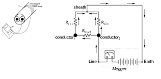
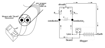
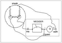
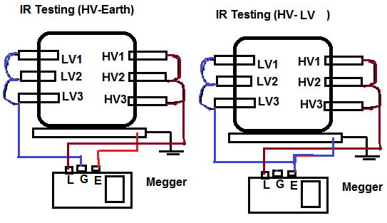
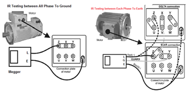
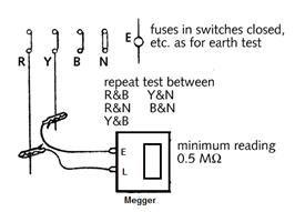
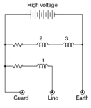
  • Meggers is equipped with three connection Line Terminal (L), Earth Terminal (E) and Guard Terminal (G).

  • Resistance is measured between the Line and Earth terminals, where current will travel through coil 1. The “Guard” terminal is provided for special testing situations where one resistance must be isolated from another. Let’s us check one situation where the insulation resistance is to be tested in a two-wire cable. * To measure insulation resistance from a conductor to the outside of the cable, we need to connect the “Line” lead of the megger to one of the conductors and connect the “Earth” lead of the megger to a wire wrapped around the sheath of the cable.

  • In this configuration the Megger should read the resistance between one conductor and the outside sheath. * We want to measure Resistance between Co…

Electrical Energy Saving Tips

ELECTRICAL ENERGY SAVING TIPS

HOW TO SAVE ELECTRICAL ENERGY AT HOME

In our home we use lot of electrical equipment like Tv, Freeze, Washing machine,Mp3 player. music system, computer laptop. But we have not adequate knowledge for how to use this electrical equipment in proper way Due to this ignorance we are paying more electricity Bill which we are not actually use.

Do you know in actual we are consuming more electricity or paying more amounts what we actually not use it?

According to the energy auditors we can easily save between 5 and 10% of their energy consumption (and costs) by changing our behavior such as switching electrical equipment off at the mains rather than leaving it on standby, turning off lights when they’re not being used

By saving Electrical energy will directly reflected to saving money so it is very necessary to under stood ghost unit or amount which we are paying without using the appliances.

The major appliances in your home — refrigerators, clothes washers, dishwashers — account for a big chunk of your monthly utility bill. And if your refrigerator or washing machine is more than a decade old, you’re spending a lot more on energy than you need to.

Today’s major appliances don’t hog energy the way older models do because they must meet minimum federal energy efficiency standards. These standards have been tightened over the years, so any new appliance you buy today has to use less energy than the model you’re replacing. For instance, if you buy one of today’s most energy-efficient refrigerators, it will use less than half the energy of a model that’s 12 years old or older.

LIGHTING

  • Get into the habit of turning lights off when you leave a room. —-Saving Energy 0.5 % * Use task lighting (table and desktop lamps) instead of room lighting. * Take advantage of daylight * De-dust lighting fixtures to maintain illumination—–Saving Energy 1 % * Compact fluorescent bulbs (CFL):
  1. CFL use 75% less energy than Normal bulbs. 2. CFL are four times more energy efficient than Normal bulbs. 3. CFL can last up to ten times longer than a normal bulb.
  • Use electronic chokes. in place of conventional copper chokes.—-Saving Energy 2 % * Get into the habit of turning lights off when you leave a room. * Use only one bulb for light fittings with more than one light bulb, or replace additional bulbs with a lower wattage version. * Use energy-saving light bulbs that can last up to ten times longer than a normal bulb and use significantly less energy. A single 20- to 25-watt energy-saving bulb provides as much light as a 100-watt ordinary bulb. * Use tungsten halogen bulbs for spotlights—they last longer and are up to 100% more efficient. * Fit external lights with a motion sensor. * Use high frequency fittings for fluorescent tubes because they cut flicker and are even more efficient than energy-saving light bulbs. They are suitable for kitchens, halls, workshops and garages.

SAVE ON YOUR FRIDGE & FREEZER:

  • Defrost your fridge regularly. * Check that the door seals are strong and intact. * Don’t stand Freezer’s Back Side too near the Wall. * Avoid putting warm or hot food in the fridge or freezer—it requires more energy to cool it down. * Clean condenser coils twice a year. * Get rid of old refrigerators! They use twice the energy as new Energy Star® models. * Keep refrigerators full but not overcrowded. * Defrost your fridge regularly. When ice builds up, your freezer uses more electricity. If it frosts up again quickly, check that the door seals are strong and intact. * Do not stand the fridge next to the oven or other hot appliances if you can help it. Also ensure there is plenty of ventilation space behind and above it. * Keep the fridge at 40°F and the freezer at 0°F. Empty and then turn your fridge off if you go on a long vacation (but make sure you leave the door open). * Aim to keep your fridge at least three-quarters full to maintain maximum efficiency. A full fridge is a healthy fridge. * Avoid putting warm or hot food in the fridge or freezer—it requires more energy to cool it down.

AIR CONDITION UNIT

  • For Home Purpose use Window unit Instead Of Split Unit. * For Office and Commercial Purpose Use Split AC instead of Window unit. * Consider installing a programmable t. Just set the times and temperatures to match your schedule and you will save money and be comfortably cool when you return home. * Get air conditioner maintenance each year. * Checks the condenser coils, the evaporator coils, the blower wheel, the filter, the lubrication and the electrical contacts. * Replace worn and dirty equipment for maximum efficiency. * Replace air conditioner filters every month. * Turn off central air conditioning 30 minutes before leaving your home. * Consider using ceiling or portable fans to circulate and cool the air. * Try increasing your air conditioner temperature. Even 1 degre…
L

Method for Installation of DB or Panel-(Part-1)

METHOD FOR INSTALLATION OF DB OR PANEL-(PART-1)

PURPOSE:

  • This method of statement describe the procedure for safely installation and testing of DB and LV Panel as per contract specification and as per the standard Practice and Code.

GENERAL EQUIPMENT & TOOLS:

  • The equipment that will be engaged for Installation of Panel ,D.B will be * Tool Box with Screwdriver, Pliers, Spanner , Hammer * Drilling Machine with various Bits , Grinding & Cutting Machine * Electrical Tester , Continuity Tester ,Multi Meter , Earth Tester , IR Tester * Wire Cutter , Blower ,Crimping Tools * Knockout punch and Flat File * Marker, Measuring tape, Level gauge / Spirit level. * Ladder / Scaffolding / Mobile scaffold * Chain Block and Pipe Wrench * Portable Lights * Removable Barricades

STORAGE & MATERIAL HANDLING:.

  • Suitable lockable storage shall be made on Site. * The storage area must be free from dust and Water leakages / seepages. * The DB, Panel and Accessories shall be unloaded with care in designated area of the Store to avoid any damages and against the effects of weather or any construction activities of Site. * The Material will be stacked / unload in the site store on a proper stand on wooden loft on a flat surface at a sufficient height from Ground. * Materials shall be stored in a place free of water and adequately covered to avoid any kind of damages. * Proper protection should be given to the material by means of covering the material with Tarpaulin sheet etc. * If they are dispatch in packs or pallets, each pack of pallet shall be lifted individually with suitable lifting equipment. * The material shall be transported / Shifted in their original packing to Site location.

INSPECTION OF MATERIALS:

  • Inspection of Materials: * Check the reference of delivered material against approved submittal and purchase order. * Check The Material according to its Type, Size, Make * Physical Damages Inspection: * In case of any damages observed during inspection, the concern report will be issued and Material shall be returned to the supplier for replacement.

SEQUENCE OF INSTALLATION WORKS:

(1) SHIFTING OF PANEL ON SITE

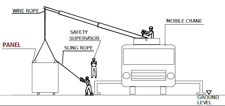
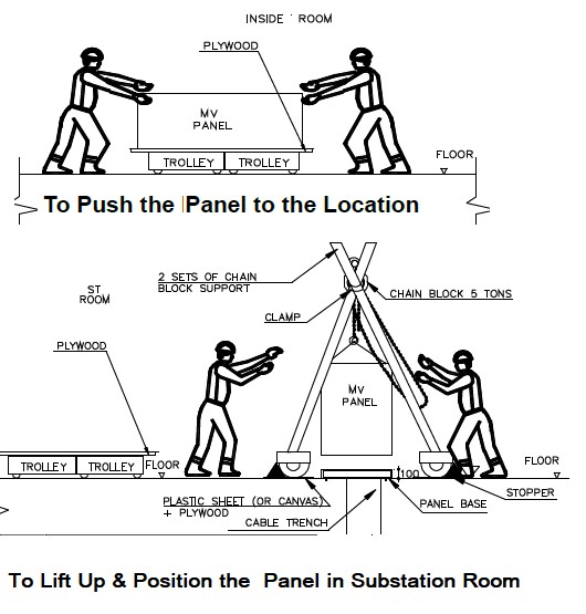
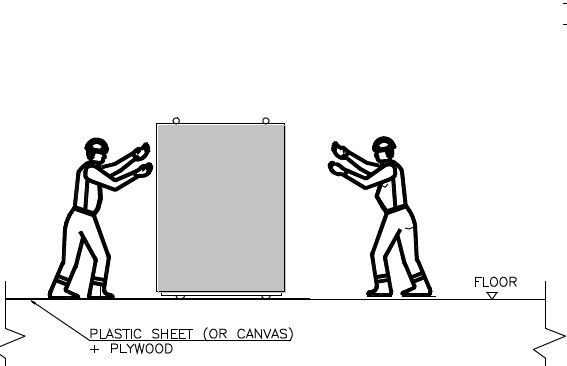
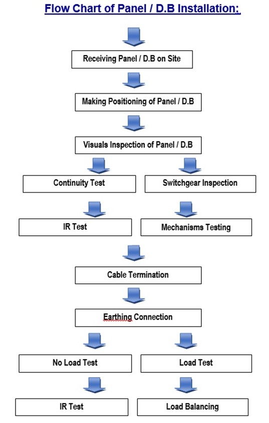
  • Prior to commencement of Panel installation works, areas and access shall be checked and confirmed by safety officer, that they are in a suitable Condition for installation works. * Decide appropriate Size of Crain / Hydra according to weight of Panel. * Panel shall be carefully unloaded or shifted to the site by using Crane/Hydra or by sufficient manpower and moved to a defined installation location. * Remove the packing and ensure that the panel is free from transportation damages * Check The shop drawings, Material submittals, Method statement, ITP & HIRA are approved, * Ensure all contents are available inside the panel. * Ensure control wiring identification shall be correctly done. * Megger shall be used having a valid calibration certificate.

1

(2) INSTALLATION OF PANEL:

  • Marking of Panel Position: * For floor mounted panel, the exact location of the panel and fixing holes to be marked on the concrete plinth for the installation.

2

  • Remove the Factory packing and ensure that the LT panel is free from transportation damages

3

  • Install the panel in proper alignment and fix properly.

4

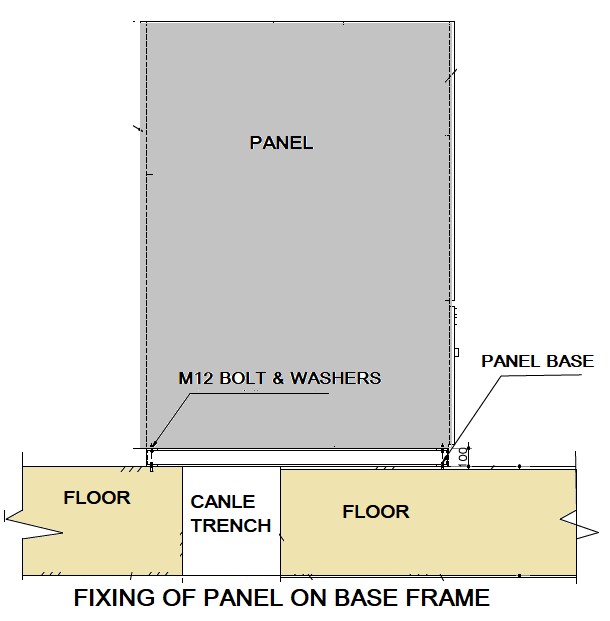
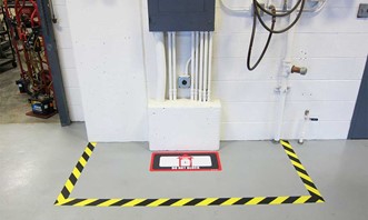
  • To secure panel base to the floor using M12 anchor bolts. * Access around the panel to be checked for future maintenance as per regulations. * Ensure the services contains water is away from the panel or properly protected against any accidental leakages. * Incoming and outgoing cables shall be marked/identified as per approved shop drawing. * Mark the fixing position of the DB’s support as per approved shop drawing and coordinate with other equipment and services. * After marking are then drilled according to the selected sizes of anchor bolts to appropriate depth as per approved shop drawing. * Locknuts on the anchor bolts will ensure a permanent fixing of the DB support to the wall/slab. * After installation of DB supports, installing position of the DB as per approved shop drawing. * Ensure that painting of the wall is completed prior to marking and mounting of DB. * All DBs wall mounting and floor mounted arrangement will be in accordance with approved shop drawings and the approved material submittal. * If there is more than one DB to be installed at the same location, they shall be installed side by side and clearance shall be maintained as per approved shop drawing. * The height of Distribution Board shall be maintained as per approved shop drawing so that easy access for termination of cables and other maintenance work can be carried out. * Check the position according to the approved shop drawings. * Check & ensure adequate space is available for maintenance * After installation, the panel shall be properly cleaned and protected to prevent dust & contamination. * Before beginning …
L

Method for Installation of DB or Panel-(Part-2)

METHOD FOR INSTALLATION OF DB OR PANEL-(PART-2)

(4) ELECTRICAL CHECKS BEFORE CHARGING THE PANEL

  • TESTING CONTINUITY BETWEEN ALL METAL PARTS AND GROUND * For performing this test, it is generally recommended to use a milliohm meter for continuity measurement. * INSULATION RESISTANCE TESTS For SWITCHGEAR * It is recommended to perform these tests before connection starting so all isolating devices will be closed. * If cables are already connected, open the isolating devices before any test. * Disconnect the ground sensing device and the control cables. * Using a 1000 V DC megohmmeter, measure the insulation resistance after a one minute Electrification time between : * 1) Phase to Phase * 2) Phase to Neutral * 3) Phase to Ground * 4) Ground to Earth * Using a 500 V DC megohmmeter, measure the insulation resistance after a one minute electrification time between: * 1) Auxiliary circuit and ground. * Reconnect the cables after testing. * Control Wiring Electrical Tests for Switchgear and Switchboards * Perform insulation-resistance tests on control wiring with respect to ground. Apply 500 volts dc for 300-volt rated cable and 1000 volts dc for 600-volt rated cable for one minute each. * Important: Units with solid-state components could be damaged if not properly isolated (via removal of plugs and/or fuses) before applying test voltage. Be sure to follow all manufacturers’ recommendations when performing dielectric tests on solid state components * Minimum insulation-resistance values of control wiring should be comparable to previously obtained results but not less than two megohms.

CHARGING & TESTING OF PANEL:

  • Cable Terminations: * Identify cable to be laid and Cut the cable to required length. * Put temporary marker onto the cable. * Carefully pull (using suitable method) and lay the cable to its route * Make appropriate opening (Cut-out) in DB /PANEL for inserting the cable with a rubber gasket so that there will be no sharp edges and secure the wire insulation from damage. * Gland the cables using appropriate cable glands size. * Terminate cables inside enclosure by securing cables to switchboards with gland bracket; and enclosure with glanding plates or fabricated steel extension boxes. * Slice the cable and identify cores to be used. Installed the ferrule number and cable lug * Dressing the cable inside the panel and Secure the cables (if necessary) with cable ties or other suitable method * Install cable marker / tag as specified * Terminate the cable properly & as per termination schedule * Earth the glands to the equipment earth grid * After complete termination of wire/cable same DB compartment shall be cleaned and fixed door. * Earthing Connections: * The Panel Main earthing bar is to connected to earth electrode or earthing Grid by Suitable size of 2 No’s of Eathing Strip or Earthing Wire via testing joints. * Energize the Panel * Switch off All Switchgear of Panel. * Connect the incoming cables of Panel to the Power Supply Source. * Check healthy ness of Power Supply at incoming of Panel. * NO LOAD: * Measure input Voltage of Power Supply between Phase to Phase, between Phase and Neutral and between Neutral and Ground. * If measured incoming Voltage is within limit than Switch ON the Main Breaker of Panel. * Measure Voltage on Bus bar between Phase to Phase, between Phase and Neutral and between Neutral and Ground. * If measured Bus bar Voltage is within limit than Panel should operate on NO LOAD Condition for 5 minutes to observe any heating, sparking and performance of accessories of Panel. * After 5 minute, one by one Switch ON the all Circuit Breaker of Panel. * ON LOAD: * Measure Voltage on each outgoing feeder of panel between Phase to Phase, between Phase and Neutral and between Neutral and Ground. * If measured Voltage of outgoing feeders are in within limit than Panel should Energize for 2 hours and verify complete performance. Check for any unusual temperature rise in cables, terminals and protective devices. * Correct Phasing: * Check Phase Sequence of Power Supply at Outgoing Circuit of Panel. * If there is not correct phase sequence for three phase power supply, reverse one phase at incoming side of Panel. * Indicators * Check all Power Supply ON /OFF / TRIP indicator works properly. * If any associated converters check the indications to the corresponding output terminal block. * Under/Overvoltage Protection * Check the relay operation and adjust to the desired rating. * The protection information reports shall be checked up to the distribution board output terminal block. * Automatic Transfer Switches * Check mechanical and / or electrical interlocks. * With the both available supplies (Main Power & D.G Power) confirm the functional checks by presence of voltage, loss of supply, restoration of supply in manual and in automatic mode. * The both incoming supplies are readiness…
Cover image
L

Method for Installation of Conceal & Surface Conduits (Part-1)

METHOD FOR INSTALLATION OF CONCEAL & SURFACE CONDUITS (PART-1)

(A) PURPOSE: .

  • This method explains the sequence of activity for safely installation of PVC / GI Conduits and it’s accessories in the concrete slabs / columns, in block works and on Surface as per the standard Practice and Code.

(B) STORAGE & MATERIAL HANDLING:.

  • The storage area must be free from dust and Water leakages / seepages. * Manufacturer recommendation shall always be followed in loading/unloading and storing of Material. * Material and its accessories shall be unloaded handle with care in designated area of the Store (Do not directly drop to Ground) to avoid any damages. * Materials shall be stored in a dry place which is free from water or from weather effects and protection should be given to the material by means of covering the material with Tarpaulin sheet. * The Material will be stacked / unload in the site store on a proper stand on wooden loft on a flat surface at a sufficient height from Ground. * If Material are dispatch in packs or pallets, each pack or pallet shall be lifted individually with suitable lifting equipment. * The material shall be transported / Shifted in their original packing to Site location. * The Material should be visually inspected for damage, which may have occurred during transport. * If the Material is found defective it shall not be installed and the cable shall be returned to the supplier for replacement.

(C) INSPECTION OF MATERIALS:.

  • Check The Material according to its Type, Size, Make * Visual inspection: * Type and Make of Conduit and Accessories Material * Length , Width and thickness of PVC / GI / MS Conduit Material and Accessories * Physical Damages Inspection: * Damage on Material and it’s Accessories * In case of any damages observed during inspection, the concern report will be issued and Material shall be returned to the supplier for replacement.

(D) CONCEALED CONDUIT IN SLAB / COLUMN:.

  1. SHIFTING MATERIAL TO WORKING AREA:
  • PVC Conduit and its accessories shall be carefully unloaded or shifted to the site by using Crane/Hydra or by sufficient manpower and moved to a defined installation location. * Remove the packing and ensure that the material is free from transportation damages * Check and ensure that approved drawings, the correct size and type of Conduit & its accessories are ready for installation. * Ensure that Conduit and its accessories received from site store for the installation are free of rusty parts and damages.
  1. MARKING ELECTRICAL POINT / WALL CONDUIT DROP ON SLAB:
  • Ensure that the civil activities are finished I,e Slab Shuttering Work and Steel Work and Site is ready for Electrical Work on Slab. * After completing the first layer of steel, start marking of Ceiling Points and Wall Drop Points on Slab as per approved Site Drawings. * Mark first the wall location for lower floor in slab as per latest Architecture layout so that it will be easy to locate the drops for switch, Wall Light Points and any other drops required for electrical system. * Mark the opening size in Slab or in Beam i.e window, door and shaft as per approved electrical drawing to avoid passing wall conduit drop on that area. * Mark the Electrical points on the slab, Wall Conduit Drop in Beam as per approved Electrical Shop Drawing. * Make sure that marking of Wall conduit drop is placed in center of wall, it is not out from wall or not move to any face of wall. * For initially use marker / Chalk for making location of electrical point on slab and wall drop after that apply oil paint on that location before conducting work so after de shuttering ,the JB or conduit drop is easily visible on slab or on beam.
  1. INSTALLATION OF JUNCTION BOX AND CONDUIT:
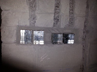
  • Chalk will be used to mark the PVC conduit route. Make sure that size of conduit is as per approved Electrical Shop Drawing. * Ceiling Conduits shall be laid on the prepared shuttering work of the ceiling slab before concrete is poured. The conduits, boxes, accessories, joints, etc. shall be laid along with the conduits. * Use Deep Junction Box for surface mounted lighting Fixtures and for Cable Pulling. * Use long radius bend or make as per site requirement by using PVC Conduit bending spring. * Joints between PVC conduit + fittings shall be made with suitable adhesive. * Try to avoid the overlapping of conduits and keep some distance between the conduits for low current and power/Lights. * To maintain at least 20mm spacing gap between PVC conduits running in parallel. To allow adequate / sufficient space between formwork and conduit so that embedded conduit is fully covered by concrete and will not result in any honeycomb or structural defects in the future. * Concealed conduits in slabs shall be brought out as vertical drops in beams, wherever such drops are required. All vertical conduits in beams shall be left protecting …