Site logo
Electrical Engineering Academy

Diesel Generator Installation Guideline

DIESEL GENERATOR INSTALLATION GUIDELINE

August 10, 2023 1 Comment

Guideline for Generator (Government of Kerala-Department of Electrical Inspectorate)

SR. NO Capacity of Generator Category 1 Up to 10KVA Portable Generator 2 10KVA to 100KVA Small Generators 3 100KVA to 1000KVA Medium Generators 4 Above 1000KVA Large Generators

Guideline for Portable Generator (Government of Kerala-Department of Electrical Inspectorate)

Size Generators up to 10kVA rating shall be treated as portable generators ELCB Size ELCB having an operating time of 20ms at a residual current of 30mA shall be provided. Neutral For 1phase generators one terminal shall be connected to earth and designated as the neutral. 3phase generators shall have their windings connected in star, with the star connection made available and connected to earth. Single Phase DG use for Three Phase Supply The supply from a single-phase generator shall be feed to a three-phase supply system through a 4-pole change over switch subject to the following conditions: (a) The neutral conductors of the load side and generator side shall be of adequate capacity to carry the total current in the neutral. (b) The 3 poles in the 4 pole change over switch shall be linked by using rigid conductors of adequate short circuit and continuous current rating capacity Location Portable generators shall be kept at a place, sufficiently ventilated so as to avoid possible hazards due to the accumulation of smoke and pollution.

Guideline for Medium Voltage Generator (Government of Kerala-Department of Electrical Inspectorate)

APPROVAL FROM ELECTRICAL INSPECTOR NOT Required: For generators of 10kVA to 30kVA rating completion report and SLD shall be submitted with a certification by the owner and the contractor stating that the electrical installation work is carried out by using change over switch, cable, MCB, etc. of standard make and with ISI mark for issuing the sanction for energization. Required: For generators above 30kVA prior scheme approval shall be obtained Meters Watt-hour meter and ammeters in each phase shall also be provided in GCP. For generators of 500 kVA and above, kVA/KW meter and P.F. meter shall also be provided Exhaust Pipe Exhaust pipe of DG sets shall maintain a minimum height of 1.8 m clearance from floor level and shall be extended to a height of at least 1m above the building. Clearance Minimum 1m clearances shall be provided on three sides of a generator set. When two generator sets are installed side-by-side, minimum 2.0 m clearance shall be provided between them Location The generator sets should not be allowed to be installed above the ground floor or below first basement level of the building. There shall be provision of separate direct escape and entry into these areas from outside in case of fire. Generators Running in Parallel Double frequency meter and double voltmeter, P.F Meter shall be provided in synchronizing panel / Control Panel. For generators of 1MVA and above synchro check relay , kVA and kVAr meters, Reverse Reactive Power relays shall provide in synchronizing panel / Control Panel. Neutral switching facility shall be provided. Interlock shall be provided to ensure that the generator breaker cannot be closed unless one of the neutral is connected to the earthing system Neutral of largest capacity generator shall only be earthed. Neutrals of other generators, running in parallel, shall be in floating condition. Also ensure that generator breakers can be made ‘ON’ only if functional neutral is earthed and closed.

Guideline for Change Over Switch of Portable Generator (Government of Kerala-Department of Electrical Inspectorate)

Capacity of single-Phase Generator Change over switch rating Minimum copper area of conductors used for linking the poles Up to 3 kVA 32 A 20 sq.mm 3 to 6 kVA 63 A 40 sq.mm 6 to 10 kVA 100A 60 sq.mm

Electricity Act, 2003 (Central Act No. 36 of 2003) & Central Electricity Authority Regulations, regulation 32, 2010

Inspection of D.G by Electrical Inspector All the apparatus of capacity above 100 KVA of the generating units including generating units producing electricity from renewable sources of energy shall be inspected by the Electrical Inspector before commissioning.

General Development Control Regulations, Gujarat – 2017

No construction shall be permissible in the Common Plot except Electric substation, Transformer room, Auxiliary power generator, Box-type transformer, section feeder pillar, meter room, over and underground water tank and pump room, security cabin, Community/ Society common amenities shall be allowed to be constructed in the Common Plot subject 22.14 Emergency Power Supply for Buildings height more than 45Meter and Special Buildings 1 For every building having height more than 45mts, a stand‐by electric generator shall be installed to supply power to staircase and corridor lighting circ…
H

Basic of External Lightning Protection System (LPS)-(Part-1)

BASIC OF EXTERNAL LIGHTNING PROTECTION SYSTEM (LPS)-(PART-1)

July 27, 2024 1 Comment

INTRODUCTION:

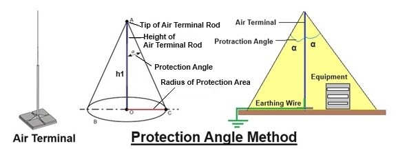
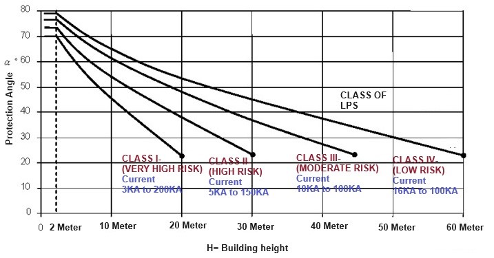
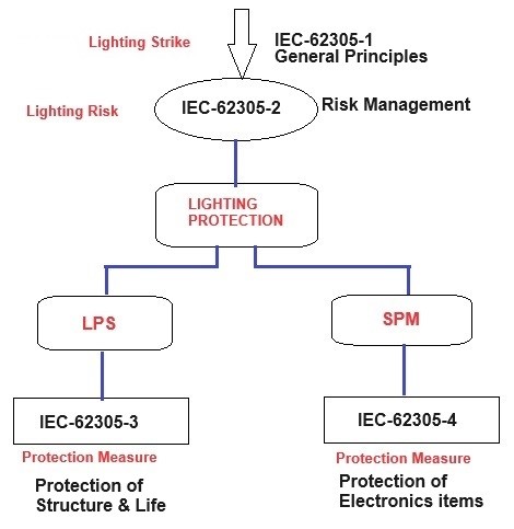
  • A lightning protection system does not attract or prevent a lightning strike. but the lightning protection system provides a low impedance path to lightning currents to flow from Lightning striking Point to the ground to prevent dangerous flashovers and lightning-caused fires. * Lightning protection systems are designed to protect structures, equipment or people from the damaging effects of lightning strikes. These systems create pathways for lightning strikes to travel safely from the top of a structure to the ground with a lightning conductor. They protect the internal electrical components of a building by preventing fires or electrocution for that all metallic installations in the building must be made at equal potential. * The basic goal of LPS is to prevent thermal, mechanical, and electrical effects that can cause damage to the protected structure or to humans via touch or step voltages within the structure.

LIGHTING PROTECTION STANDARDS:

  • There are various lighting protection standards. Widely use are * IEC 62305 * IS 2309 * NFPA 780 * NBC-2016

 IEC:62305 -Part 1 to 5:

COMPARISON BETWEEN IEC AND IS STANDARD FOR LPS: 

Comparison between IEC and IS standard for External LPS

Description LPS as per IEC 62305 LPS as per IS 2309 ESE (Early Streamer Emission) Coverage area Real, Calculated and approved design as per building type complying to IEC 62305-3. Real, Calculated and approved design as per building type complying to IEC 62305-3. Imaginary – no proof available, Not complying and national or international standard. Approvals / Applicability of latest standard IEC 62305-3 – International standard, Released in 2010 IS 2309 & IS 3043 – National standard, Released in 1989 Approved only in France which is their local standard Insurance cover Yes. Yes. No. Not approved by IS & CEA Height limitation No height limitation as the LPS is based on horizontal air terminal No height limitation as the LPS is based on horizontal air terminal Height restriction is applicable surrounding the airport area as ESE is based on Vertical air terminal. Air Termination Design Rolling sphere method Protective Angle method & Mesh method Not as per any international method. LPS for Type of Building Any type of complex building. Simple and Flat /Slopped Building Material for Air terminal & down conductor. 8mm Aluminum round, which is easier to install, bend & needs less conductor holder. 25X3 GI is used which is difficult to install, bend & needs twice the amount of conductor holder. Not as per any international method. Material compatibility Taken care using bi-metal connector No specific mention in the standard. Not taken care. Expansion /contraction of metal in summer/winter Taken care of using Expansion pieces. Not taken care Not applicable as it is based on vertical air terminal. No of Down Conductor. More than one down conductor to dissipate the Lightning current to the ground (Multiple Dissipation) Less number of down conductors when compared to IEC 62305 In most of the sites, only one down conductor is installed. Current sharing Path Many Parallel paths. LEMP has minimal effects Few parallel paths Maximum 2 Parallel paths. High LEMP can damage electronic equipment. Design of LPS based on LPL 1 to 4 backed up by IEC 62305 Based on Experience & old IEC, BS standards. Not as per any international method. Experience Used for many decades without any problem. Used for many decades without any problem. Approximately 15 years old. In Some country many buildings with ESE were damaged. Grounding Type B as per IEC 62305-1 Ring earthing as per IS 3043 Recommended only for small residences (not even apartments) where electronic equipment is not available. Installation time consuming but effective time consuming but effective less time consuming but ineffective

LIGHTING PROTECTION LEVELS:

  • Lighting Protection Level are divided into four categories. For each category, a set of maximum and minimum lightning current parameters is fixed (LPL I to IV). * The maximum values of lightning current parameters are used to design lightning protection components (e.g. Cross section of conductors, thickness of metal sheets, current capability of SPDs and Separation distance against dangerous sparking). * The minimum values of lightning current amplitude for the different LPL are used to derive the Rolling Sphere Radius to define the Lightning Protection Zone (LPZ0B) which cannot be reached by direct strike.

RELATION BETWEEN LPL AND CLASS OF LPS

Table-7, IEC- 62305-3 LPL RISK LEVEL CLASS OF LPS CLASS I Very High Risk I CLASS II High Risk II CLASS III Moderate Risk III CLASS IV Low Risk IV

CLASSIFICATION OF LPS

Table-4,…

H

Basic of External Lightning Protection System (LPS)-(Part-2)

BASIC OF EXTERNAL LIGHTNING PROTECTION SYSTEM (LPS)-(PART-2)

August 10, 2024 1 Comment

(B) ROLLING SPHERE METHOD: (SUITABLE FOR COMPLEX SHAPE BUILDING)

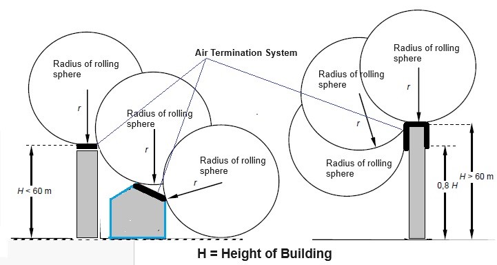
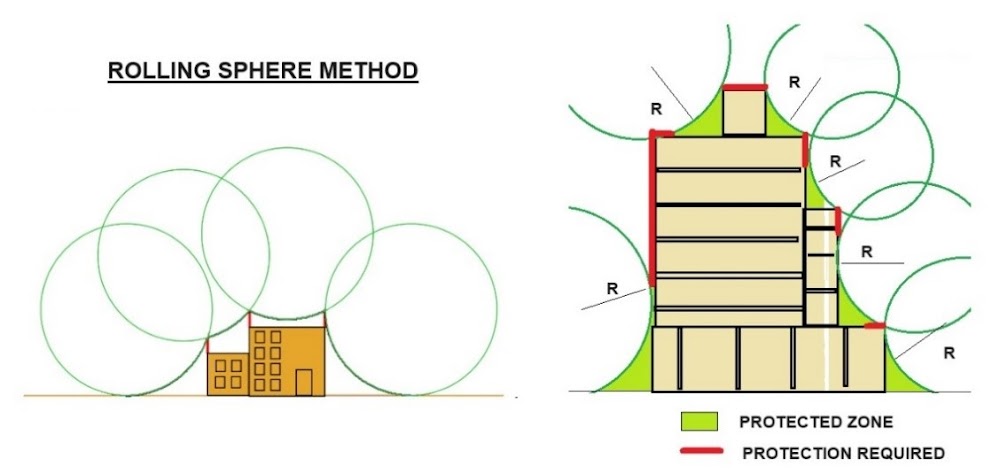
  • The rolling sphere method should be used to protect the areas of a structure when there is design limitation to use the protection angle method. * The rolling sphere method is recommended as the main method to be used in the design of lightning protection system with location of air terminals for structures with complex shapes. * This method is more accurate, and complex compared to other lightning protection schemes, because it specifies the exact number of spikes needed for each building and considers the worst-case scenarios, in which a lightning strike hits the side of the building. * Position of Air Termination Rod: * In this method, the positioning of the Air-Termination system is adequate so that no point of the structure to be protected comes in to contact with a sphere with radius ‘r’ depending on the class of LPS (see table) rolling around on top of the structure in all possible directions. In this way, the sphere only touches the air termination system (see figure). * Radius of Sphere: * The rolling sphere lightning protection method assumes the electrically charged field that produces a lightning strike has a radius “r” and the sphere with that radius rolling over the surface of the building. Any place the sphere touches the building is a location where lightning can strike the building. By installing air terminals, the sphere cannot touch the building because electrical charges flow through the lightning protection system into the ground. * The radius of the rolling sphere is correlated with the peak value of the current in the lightning that strikes the structure: r = 10xIx0.65 where I define as kA. * In the rolling sphere method, the radius of the sphere is selected in such a way that its radius is equal to the striking distance. Since the striking distance is a function of the prospective return stroke current, the radius of the sphere “r” is defined as a function of the probable return stroke current according to the relationship between the lightning striking distance and the peak return stroke current. * The lightning stroke depends on the degree of risk considered. So, for a high-risk facility, the sphere radius is at its smallest, e.g. 20meter or a 40meter diameter ball. The smallest size ball means the amount of protection installed will be at its highest. Thus, lowering the risk profile and increasing the protection afforded. * For a low-risk scenario method, the sphere radius is at its largest distance, 60 meters (120-meter diameter ball), which means a lot less hardware to install. * The radius r of the rolling sphere depends on the class of LPS as per given Table.

 RADIUS OF THE ROLLING SPHERE

Class of LPS Rolling sphere radius, r (m) CLASS I- (Very High Risk) 20 Meter CLASS II- (High Risk) 30 Meter CLASS III- (Moderate Risk) 45 Meter CLASS IV- (Low Risk) 60 Meter

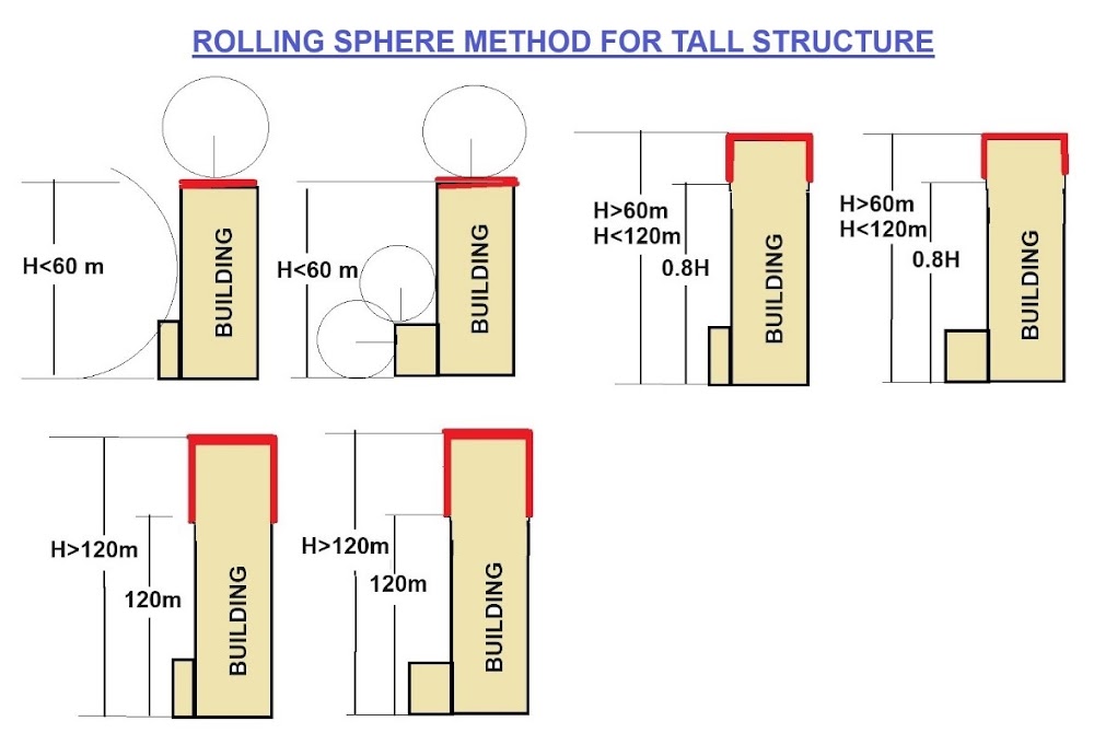
  • Figure shows the application of the rolling sphere method to different types of structures. The sphere of radius r is rolled around and over all the structure until it meets the ground plane or any permanent structure or object in contact with the ground plane which can act as a conductor of lightning. * A striking point could occur where the rolling sphere touches the structure and at such points protection by an air-termination conductor is required. * Any part of the structure that is in contact with the sphere is considered to be vulnerable to a direct lightning strike; the untouched volume defines a lightning protected zone.

  • When the rolling sphere method is applied to the structure, the structure should be considered from all directions to ensure that no part protrudes into an unprotected zone a point which might be overlooked if only front, side and plan views on drawings are considered.

PENETRATION DISTANCE:

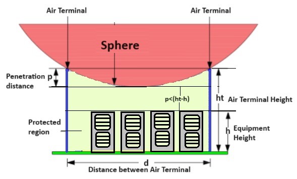
  • The distance between the two air terminals should be chosen in such a way that protection is provided for all the objects placed on the surface to be protected. * The protection of the objects placed on the surface can be ensured by calculating the penetration distance of the rolling sphere. * The distance between the level of air terminals and the least point of sphere in the space between the air terminals is called penetration distance.

  • Let us consider an object of height ‘h’ placed on the surface to be protected. Let ‘ht’ be the height of the air terminal, ‘p’ be the penetration distance and ‘d’ be the…

H

Basic of External Lightning Protection System (LPS)-(Part-3)

BASIC OF EXTERNAL LIGHTNING PROTECTION SYSTEM (LPS)-(PART-3)

September 4, 2024 1 Comment

COMPARISION OF VARIOUS PROTECTION METHOD

COMPARISION OF VARIOUS PROTECTION METHOD

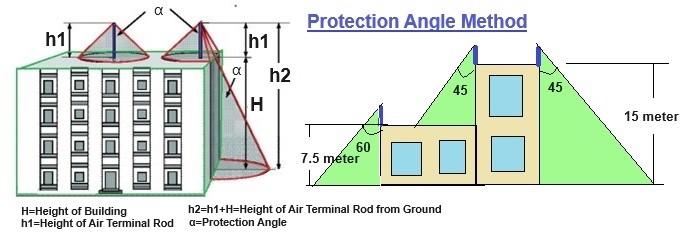
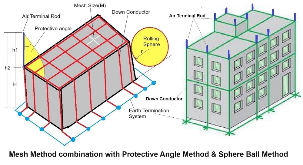
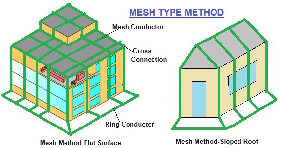
Protection Method Type of Structure Simple structure Complex shaped structure Plane Structure Protection Angle () YES NO NO Mesh Method NO YES YES Rolling sphere Method YES YES YES () This method is not suitable for structure height more than radius of the rolling sphere relevant to the selected protection level of LPS

(2) DOWN CONDUCTOR SYSTEM:

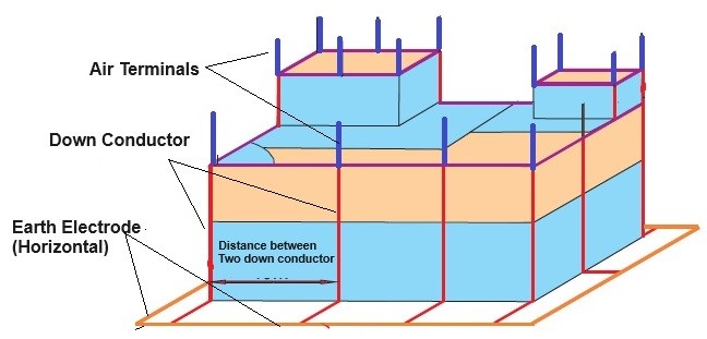
  • In Air-termination systems, down-conductor systems and earth-termination systems should be harmonized to produce the shortest possible path for the lightning current. * Down-conductors should preferably be connected to junctions of the air-termination system network and routed vertically to the junctions of the earth-termination system network. * The function of a down conductor system is to conduct the lightning impulse from air-termination system to the earthing system. The down conductor system should be installed in such a way that the following points are ensured. * (i) Several parallel current paths exist * (ii) Length of current path is kept to minimum. * (iii) Equipotential bonding to conducting parts is performed. * Selection and installation of down conductors plays a major role in protecting electrical and electronic installations in a building. The number of down conductors to a typical building depends upon the class of LPS. * A down conductor should be installed at each exposed corner of the structure and form a direct continuation of the air-termination conductors. Drown conductors are installed in such a way that they provide the shortest and most direct route to earth. Avoiding the formation of bends and loops is required. * To reduce damage caused by lightning current, the down conductors are arranged so that the current path around the building’s perimeter is parallel and at equal distances. * Even if the down conductor encased in insulating material, down conductors must not be installed in service shafts, gutters, or downspouts, as doing so invites severe damage during a lightning strike. * Electrical insulation between LPS components and other metallic installation in the building are necessary to avoid flashover between different metal parts. * Integration of down conductor with Building Natural Components: * External down-conductors should be installed between the air-termination system and the earth-termination system. Wherever natural components (Steel reinforcement, metal framework structure) are available, they can be used as down-conductors. * Down conductors are also integrated into structural steel reinforcement, metal framework of structure, steel roof, metal façade, handrails etc. is the best and practical solution for new and upcoming high raise buildings. In this integrated approach high safety is offered with no maintenance, long life, no influence on aesthetics. Separation distance need not be considered in this case. * Down conductors can be embedded in RCC columns. In this case, bonding different metallic installations in the building is simple, thereby eliminating potential differences. This integrated method is not only cost-effective but has no negative effect on the building’s aesthetics. It also reduces the failure of electronic equipment inside the building from radiated lightning effects. * Test joints are not required, and earth resistance measurements are not necessary in the location where the natural down conductors are terminated to foundation earthing.

  • Number & distance between each Down Conductor: * For each non-isolated LPS, the number of down conductors shall be not less than two and should be distributed around the perimeter of the structure to be protected. An equal spacing of the down conductors is preferred around the perimeter. The typical values of the distance between the conductors are shown below.

DISTANCE BETWEEN DOWN CONDUCTORS

(IEC/BS EN 62305-3 Table 4)

Class of LPS Distance between conductors CLASS I- (Very High Risk) 10 Meter CLASS II- (High Risk) 10 Meter CLASS III- (Moderate Risk) 15 Meter CLASS IV- (Low Risk) 20 Meter

  • If the distance between down-conductors is too large with the reference to the Table, the number of down-conductors should be increased to meet the required separation distance. * As stated, a down-conductor should be installed at each exposed corner of the structure, where this is possible. However, an exposed each corner does not need a down conductor if the distance between this exposed corner to the nearest down-conductors complies with the following conditions: * (i)the distance to both adjacent down-conductors is half the distance according to Tables or smaller. * (ii) the d…

Basic of External Lightning Protection System (LPS)-(Part-4)

BASIC OF EXTERNAL LIGHTNING PROTECTION SYSTEM (LPS)-(PART-4)

October 1, 2024 Leave a comment

MATERIAL COMBINATIONS AND DIMENSIONS

  • Required to use galvanically compatible metals in lightning protection system components and surface materials on which the components are mounted. For example, do not connect copper to aluminum. * Do not use together metals that are not galvanically compatible. Bad matching accelerates their corrosion in the presence of moisture. * With aluminum conductors, use only connection devices designed for aluminum. Make sure to use the right fastening torque.

 Different Contact Material

Material

Suitable Contact Material

Copper

Nickel /Brass / Tin / Lead / Stainless steel / Monel (nickel–copper alloy) Aluminum

Magnesium / Zinc / Galvanized steel / Stainless steel / Lead / Wrought iron / Galvalume (an aluminum-coated sheet steel product)

LPS MATERIAL

LPS Materials and Conditions of Use

Table-5 (IEC 62305-3)

Material Use Corrosion In Open Air In Earth In Concrete Resistance Increased by May be destroyed by Galvanic Coupling with Copper Solid Solid Solid Good in many environments Sulphur compounds – Stranded Stranded Stranded – Organic materials – – As coating As coating – – – Hot galvanized steel123 Solid Solid Solid Acceptable in air, in concrete, and in benign soil High chlorides content Copper Stranded 4 – Stranded 4 – – – Steel with electro-deposited copper Solid Solid Solid Good in many environments Sulphur compounds – Stainless steel Solid Solid Solid Good in many environments High chlorides content Stranded Stranded Stranded – – – Aluminum Solid Unsuitable Unsuitable Good in atmospheres containing low concentration of Sulphur and chloride Alkaline solutions Copper Stranded – – – – – Lead 5 Solid Solid Unsuitable Good in atmospheres with high concentration of sulphates Acid soils Copper As coating As coating – – – Stainless steel

MATERIAL DIMENSIONS

  • Several lightning protection system codes and standards define minimum dimensions for the components of a grounding system. These standards are designed to protect buildings and other inhabited or otherwise critical facilities. * Practical minimums are based on field experience and indicate what is needed to protect the installed equipment in a cost-effective way during the foreseeable technical lifetime, typically a few decades, taking into account local regulations. To ensure proper operation of the grounding system, periodic inspection and maintenance is needed

MINIMUM DIMENSIONS OF EARTH ELECTRODE AS PER IEC 623053 

  • Table 1 and Table 2 are based on standard IEC 62305-3 Ed 2. The tables list minimum dimensions for the lightning protection system equipment. * The following table lists the different materials and shapes that are used in air terminals, down conductors, and ground electrodes, including the cross-sectional area.

 Minimum Dimensions of Earth Electrodes

Table-7, IEC-62305-3

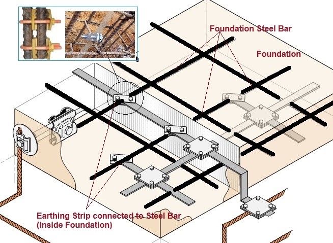
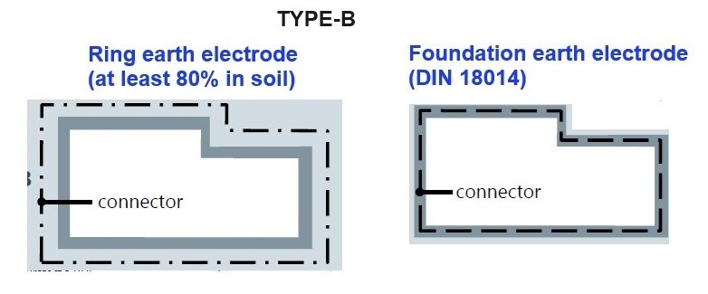
Material Configuration Dimensions Earth Rod Diameter Earth Conductor Earth Plate Copper, Tin-plated copper Stranded – 50 Sq.mm (8 mm) – Solid round 15 mm 50 Sq.mm (8 mm) – Solid tape – 50 Sq.mm (8 mm) – Pipe 20 mm – – Solid plate – – 500 × 500 mm Lattice plate – – 600 × 600 mm Hot-dipped galvanized steel Solid round 14 mm 78 Sq.mm (9.96 mm) – Pipe 25 mm – – Solid tape – 90 Sq.mm (10.7 mm) – Solid plate – – 500 × 500 mm Lattice plate – – 600 × 600 mm Profile * – – Bare steel (Shall be embedded in concrete for a minimum depth of 50 mm.) Stranded – 70 Sq.mm (9.4 mm) – Solid round – 78 Sq.mm (9.96 mm) – Solid tape 75 Sq.mm (9.72 mm) Copper coated steel Solid round 14 mm 50 Sq.mm (8 mm) Solid tape 90 Sq.mm (10.7 mm) Stainless steel Solid round 15 mm 78 Sq.mm (9.96 mm) Solid tape 100 Sq.mm (11.28 mm) Mechanical and electrical characteristics as well as corrosion resistance properties shall meet the requirements of the future IEC 62561 series. In case of a type B arrangement foundation earthing system, the earth electrode shall be correctly connected at least every 5 m with the reinforcement steel. * Different profiles are permitted with a cross-section of 290 mm2 and a minimum thickness of 3 mm, e.g. cross profile.

MINIMUM CROSS-SECTIONAL AREA OF AIR-TERMINATION CONDUCTORS

Minimum Cross-sectional Area of Air-termination Conductors

Table 6 (IEC 62305-3)

Material Configuration Cross-sectional Area Comments Copper, tin-plated copper Solid tape 50 Sq.mm / 8mm * 2 mm min. thickness Solid round1 50 Sq.mm / 8mm * 8 mm diameter Stranded 1 50 Sq.mm / 8mm * 1.7 mm min. dia of each strand Solid round*** 176 Sq.mm /15mm 16 mm diameter Aluminum Solid tape 70 Sq.mm* 3 mm min. thickness Solid round 50 Sq.mm / 8mm * 8 mm diameter Stranded 50 Sq.mm / 8mm * 1.7 mm min. dia of each strand Aluminum alloy Solid tape 50 Sq.mm / 8mm * 2.5 mm min. thickness Solid round 50 Sq.mm / 8mm * 8 mm diameter Stranded 50 Sq.mm / 8mm * 1.7 mm min. dia of each stra…

H

Lighting Arrester

LIGHTING ARRESTER

LIGHTING AND VOLTAGE SURGE

  • Lightning can create voltage surges in several of the following ways. Lightning can score a direct hit on your house. It can strike the overhead power line which enters your house, or a main power line that is blocks away from your home. Lightning can strike branch circuitry wiring in the walls of your house. Lightning can strike an object near your home such as a tree or the ground itself and cause a surge. Voltage surges can be created by cloud to cloud lightning near your home. A highly charged cloud which passes over your home can also induce a voltage surge. * Voltage surges can also be caused by standard on and off switching activities of large electric motors or pieces of equipment. These surges can be created by a neighbor, or by a business or manufacturing facility some distance from your house. These surges are insidious and for the most part are silent. They can occur with little or no warning.

METHOD TO SUPPRESS LIGHTING AND VOLTAGE SURGE:

  • When a voltage surge is created, it wants to equalize itself and it wants to do it as quickly as possible. These things seem to have very little patience. The surges will do whatever it takes to equalize or neutralize themselves, even if it means short circuiting all of your electronic equipment. * The method of providing maximum protection for equipment is quite simple. Create a pathway for the voltage surge (electricity) to get to and into the ground outside your house as quickly as possible. This is not, in most cases, a difficult task. * The first step is simple. Create an excellent grounding system for your household electrical system. The vast majority of homes do not have an excellent grounding system. Many homes have a single grounding rod and /or a metallic underground water pipe which are part of the electrical grounding system. In most cases, this is inadequate. The reason is somewhat easy to explain. Imagine putting a two inch fire hose into your kitchen sink and opening the nozzle to the full on position. I doubt that the drain in your sink could handle all of the water. Your grounding system would react in the same way to a massive voltage surge. Just as the water jumps out of the sink, the electricity jumps from the grounding system and looks for places to go. Frequently it looks for the microchips in your electronic devices. They are an easy target. They offer a path of least resistance. * Voltage surges want to be directed to the grounding system, and when they do, they want to get into the ground around your house in a hurry. You can achieve this by driving numerous grounding rods into virgin soil around your house. These rods should be UL approved and connected by a continuous heavy solid copper wire which is welded to each grounding rod. This solid copper wire begins on the grounding bar inside of your electrical panel and terminates at the last grounding rod. Avoid using clamps if at all possible. Over time, the connection at the clamp can corrode or become loose creating tremendous resistance. This will act as a roadblock to the electricity trying to get into the ground around your home. * The grounding rods should be at least ten feet apart from one another. They should be located in soil which readily accepts electricity. Moist clay soils are very desirable. Rocky, sandy, or soils with gravel generally have high resistance factors. Electricity has a tough time dissipating into them. Resistance readings should be in the range of 10 to 30 ohms. The lower the better. * The second step in household surge protection is to install a lightning arrester inside of your electric service panel. These devices can be extremely effective in intercepting large voltage surges which travel in the electric power lines. These devices capture the voltage surges and ‘bleed’ them off to the grounding wire which we just spoke of. If for some reason you do not have a large enough grounding wire, or enough ground rods, the arrester cannot do its job. It must be able to send the surge quickly to the ground outside of your house. Almost every manufacturer of circuit breakers makes one to fit inside their panel. They can be installed by a homeowner who is experienced in dealing with high voltage panels. If you do not have this capability, have an experienced electrician install it for you. * The final step in the protection plan is to install ‘point of use’ surge suppression devices. Often you will see these called ‘transient voltage surge suppressors’. These are your last line of defense. They are capable of only stopping the leftover voltage surge which got past the grounding system and the lightning arrester. They cannot protect your electronic devices by themselves. They must be used in conjunction with the grounding system and the lightning arresters. Do not be lulled into a false sense of security if you …
Cover image
H

Selection of Surge Protective Device (SPD)- (Part 4)

SELECTION OF SURGE PROTECTIVE DEVICE (SPD)- (PART 4)

TYPICAL SYSTEM VOLTAGE & MCOV RATING (AS PER IEEE):

Typical IEEE System Voltages Normal (Line to Line) Voltage (KV rms) Maximum ( Line to Line ) Voltage (KV rms) Maximum (Line to Ground) Voltage (KV rms) Min MCOV kV rms kV rms kV rms kV rms 2.40 2.52 1.46 1.46 4.16 4.37 2.52 2.52 4.80 5.04 2.91 2.91 6.90 7.25 4.19 4.19 8.32 8.74 5.05 5.05 12.0 12.6 7.28 7.28 12.5 13.1 7.57 7.57 13.2 13.9 8.01 8.01 13.8 14.5 8.38 8.38 20.8 21.8 12.6 12.6 22.9 24.0 13.9 13.9 23.0 24.2 14.0 14.0 24.9 26.2 15.1 15.1 27.6 29.0 16.8 16.8 34.5 36.2 20.9 20.9 46.0 48.3 27.9 27.9 69.0 72.5 41.9 41.9 115.0 121 69.8 69.8 138.0 145 83.8 83.8 161.0 169 98 97.7 230.0 242 140 140 345.0 362 209 209 500.0 525 303 303 765.0 800 462 462

TYPICAL SYSTEM VOLTAGE & MCOV RATING (AS PER IEC):

Typical IEC System Voltages Normal (Line to Line) Voltage (KV rms) Maximum ( Line to Line ) Voltage (KV rms) Maximum (Line to Ground) Voltage (KV rms) Minimum Uc kV rms kV rms kV rms kV rms 3.3 3.7 2.1 2.1 6.6 7.3 4.2 4.2 10.0 11.5 6.6 6.6 11.0 12.0 6.9 6.9 16.4 18.0 10.4 10.4 22.0 24.0 13.9 13.9 33.0 36.3 21.0 21.0 47.0 52 30.1 30.1 66.0 72 41.6 41.6 91.0 100 57.8 57.8 110.0 123 71.1 71.1 132.0 145 83.8 83.8 155.0 170 98.3 98.3 220.0 245 142 142 275.0 300 173 173 330.0 362 209 209 400.0 420 243 243

SPD AND FUSE / CB CO-ORDINATION CHART:

Fuse/CB co-ordination chart Incoming feeder fuse rating (A) Incoming feeder CB Rating (A) SPD fuse rating (A) SPD CB rating (A) 16 6 10 4 25 10 16 6 32 16 20 10 40 20 25 16 63 32 40 20 80 40 50 25 125 63 80 40 160 80 100 50 250 125 160 80 500 250 320 160

SAMPLE SPECIFICATIONS OF SPD FOR 277/480V SUPPLY SYSTEM

  • Voltage :277/480V 3Ø WYE, 480V 3Ø Delta * Frequency: 50/60Hz * Surge Technology: 40mm MOV * Nominal Discharge Rating (IN):20kA * Maximum Continuous Operating Voltage (MCOV): 320V * L-L=640V * L-N=320A * L-G=320A * G-N=320A * Maximum Surge Current, Per Mode (Per Phase) : 200kA (400kA * Voltage Protection Rating (VPR) (Clamping) : 800V(L-N)/700V(L-L) * Short Circuit Current Rating (SCCR): 10kA * Connection Type: Parallel Connection

REASON FOR FAILURE OF SPD :

Most SPDs will last for many years. The things that cause sudden failure are

  • External supply faults such as overvoltage -faulty transformer, MV lines * Local supply faults -broken or ungrounded neutral. * Wrongly-selected SPD voltage. * A surge in excess of the SPD’s rating.

CLASSES’ OF SURGE ARRESTORS ACCORDING TO IMPULSE CURRENT:

Untitled

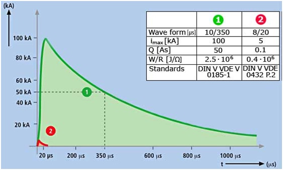
 1 = Test impulse current for lightning current arresters

2 = Test impulse current for surge arresters

  • There are 3 x main categories of lightning surge arresters. * Class 1/A – (10/350) lightning current arresters, which can withstand direct lightning * Class 2/B – (8/20) surge arresters, to protect against induced surge currents * Class 3/C – (8/20) surge arresters, to protect against induced surge currents

 MEANING OF 20KA (8/20ΜS) IMPULSE CURRENT.

  • In 8/20μ The first value (8) is the rise time (from 10% to 90% of peak). The second value (20) is the duration for the test transient to decrease to half its peak value.

STANDARD FOR SPD:

  • Underwriter laboratories—UL 1449 (3rd Edition 2009) * IEEE C62.45 (2002) * NECT National Electrical Code Articles 245, 680 and 800. * NFPAT 780 Lightning protection code recommendations for the use of surge protection devices at a facility service entrance.
H

Selection of Surge Protective Device (SPD)- (Part 3)

SELECTION OF SURGE PROTECTIVE DEVICE (SPD)- (PART 3)

TYPE OF SPD:

TYPE 1 SPD:

  • Protection for : Transient Over voltages due to Direct Lightning Strokes * Location : It is installed at any location between the secondary of the utility service transformer and the service entrance primary disconnection

  • It is installed in the main electrical switchboard when the building is equipped with a lightning protection system. * It protects against external surges caused by lightning or utility capacitor bank switching. * These devices to discharging a very high lightning current from earth to the power distribution system. * Current ratings: 10Ka to 35Ka – 10/350µs wave form.

  • Required Dedicated Fuse / Circuit Breaker for SPD : No * Risk Factor : Very strong risk Area

TYPE 2 SPD:

  • Protection for : Transient Over voltages due to Switching and Indirect Lightning Stroke. * Location: It is installed in the main distribution switchboard.

  • It is designed to discharge the currents generated by indirect lightning strokes and causing induced or conducted overvoltage on the power distribution network. * It protects against residual lightning energy, motor driven surges and other internally generated surges.

  • Current ratings: 5Ka to 200 Ka – 8/20µs wave form. * Required Dedicated Fuse / Circuit Breaker for SPD : May or May Not

  • Risk Factor : Common risk Area

TYPE 3 SPD:

  • Protection for: Sensitive Loads. * It is installed as a supplement to Type 2 devices and to reduce the overvoltage at the terminals of sensitive equipment. * Their current discharge capacity is very limited. As a consequence they cannot be used alone. * Installed at minimum conductor length of 10 meters (30 feet) from the electrical service panel to the point of utilization * Provides point-of-use protection, easily replaceable and it provides the last line of defense against a lightning strike. * Risk Factor : Very strong & common risk Area

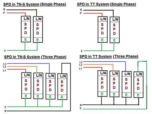
CONNECTION OF SPD IN DISTRIBUTION BOX.

  • In common mode: Phase to earth or neutral to earth * In differential mode: Phase to phase or phase to neutral

 0

FACTORS EFFECT ON SPD PERFORMANCE:

(1) LOCATION OF SURGE PROTECTION DEVICE:

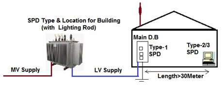
  • Lightning protection should be installed on a overall viewpoint of Protection. * For large industrial plants, data centers, hospitals, a risk assessment method must be used to guide in choosing optimal distance. * In other cases like housing, offices, buildings Where there is not or less sensitive industrial risks, we may adopt following principle to select SPD.Type 2 surge protective device should be installed in the electrical installation’s incoming Main switchboard. * If the distance between that surge protective device and the equipment to be protected is more than 30 meters, than additional surge protective device (Type 2 or Type 3) should be installed near the equipment.

1

  • When the building is equipped with a lightning protection system, a Type 1 surge protective device must be installed at the incoming Main Switch Board. There exist surge protective devices combining Type 1 and Type 2 in the same enclosure. 2

  • The Lightning rods have to be located on the highest points of the structure, taking into account the location of the grounding, and that the path of the down conductors are as short and straight as possible .

(2) SIZE OF DOWN CONDUCTOR:

  • Lightning is a phenomenon that generates a high frequency voltage. The length of the cables must be taken into account in cases of high frequency. * The down conductors may be tapes, stranded wire or solid round. * The minimum cross section must be * 1 meter of cable crossed by a lightning current generates an overvoltage of 1,000V. * Mandatory in Standard IEC 60364-5-534: * L (length of cables) < 50cm, * Cable cross-section of Cable (S) < 16mm² (Type 1). * Cable cross-section of Cable (S) < 4mm²(Type 2).

(3) PLACEMENT OF DOWN CONDUCTOR

  • Down conductor will be placed on the outside of the structure. * When it is impossible to make a down conductor on the outside, conductors can be introduced in a non-flammable insulating pipe, with a minimum section of 2000 mm2, for this purpose. * The down conductors on the inside decrease the effectiveness of lightning protection, increase the risk of over voltages penetration of and difficult the verification and maintenance of installation.

(4) NUMBER OF DOWN CONDUCTOR

  • At least one down conductor for every lightning rod. A minimum of two down conductor when, * (1) The horizontal Projection length of the conductor exceeds its vertical projection length. * (2) The height of the structure is greater than 28 meter. * Equi potential bonding will be mad…

Selection of Surge Protective Device (SPD)- (Part 2)

SELECTION OF SURGE PROTECTIVE DEVICE (SPD)- (PART 2)

SIZE OF SURGE PROTECTION DEVICE (SPD) DEPENDS UPON LOCATION OF PANEL:

  • Panel location within the electrical system is more important than the panel’s size. * The location of the panel within the facility is much more important. IEEE C62.41.2 defines the types of expected surges within a facility as: * Category C: Service Entrance, more severe environment: 10kV, 10kA surge * Category B: Downstream more than 30feet from category C, less severe environment: 6kV, 3kA surge * Category A: Further downstream, more than 60 feet from category C, least severe environment: 6kV, 0.5kA surge * When selecting the appropriate kA rating for an SPD. * Category C: 100kA to 200kA per phase * Category B: 50kA to 100kA per phase * Category A: 50kA to 100kA per phase

LARGE SIZE OF SURGE PROTECTION DEVICE (SPD) DOES NOT GIVE BETTER PROTECTION:

  • Most SPDs use a metal oxide varistor (MOV) as the main limiting device. If an MOV is rated for 10kA and having a 10kA surge, it would use 100% of its capacity. The surge will degrade the MOV a little bit. * Now if we use 20KA SPD so this SPD has two 10kA MOVs in parallel. The MOVs will equally split the 10kA surge, so each would take 5kA. In this case, each MOV have only used 50% of their capacity which degrades the MOV much less than 10KA SPD * Again It is totally misleading that two parallel path (in 20KA SPD) absorb surge faster or better than single path SPD (like 10KA SPD) of same rating. * The main purpose of having MOVs in parallel is to increase the longevity or Life of the SPD. * Again, It is need to clear that it is subjective and at some point we are only adding cost by incorporating more MOV’s and receiving little benefit. * Larger kA ratings are for redundancy & longer life only.

SPD CAN NOT GIVE 100% PROTECTION AGAINST ALL TYPES OF ELECTRICAL DISTURBANCE

  • There is a misconception about SPDs is that they are designed to protect against all Electrical problems. * SPD is not designed to protect against excessive voltage at the fundamental power frequency. It is design to give protection against surges (by direct lighting or voltage surges in line at remote location). * SPD can not give Protection against Poor Power Quality (Harmonics) * Some SPDs contain filtering to remove high frequency noise (50 kHz to 250 kHz), But SPD cannot filter harmonic loads (3rd through 50th harmonic equals180 to 3000 Hz). * SPD can not give Protection against Under Voltage. * SPD can not give protection against under voltage problems. * SPD can not give Protection against direct lighting Strikes. * An SPD can not prevent damage caused by a direct lightning strike. A direct lightning strike causes induced surges on the power line that are reduced by the SPD But SPD can not Protect against Lighting Strikes near SPD Location. * SPD can not give protection against temporary overvoltage. * Temporary overvoltage is caused by a severe fault in the utility power or due to problems with the ground (poor or nonexistent N-G bond). * Temporary overvoltage occurs when the Voltage exceeds the nominal voltage for a short duration (millisecond to a few minutes). * If the voltage exceeds 25% of the nominal system voltage, the SPD and other loads may become damaged.

SELECTION OF SURGE PROTECTION DEVICE (SPD):

  • The Size, performance and specification of SPD depend on following characteristics

Current characteristic of SPD

  • I:Surge Current Rating (KA), * In: Nominal Discharge Current (In), * Imax: Maximum discharge Current (Imax) * Short Circuit Current Rating (SCCR).

Voltage characteristic of SPD

  • Uc: Maximum Continuous Operating Voltage (MCOV), * Up: Voltage Protection Rating (VPR) or surge voltage rating (SVR) or Clamping Voltage. * TOV: Temporary Over Voltage.

(1) SURGE CURRENT RATINGS (I):

  • The peak surge current ratings of SPD are generally based on the sum of Line-neutral and Line-ground current. * A peak ampere rating per phase. (I.e. L-N 100 kA, L-G 100 kA provides 200 kA/phase). * Other Specification like MCOV, VPR, In and SCCR that have clearly defined test criteria, but for Surge Current there is no specified Test Criteria or industry-standard hence different SPD manufacturers to create their own definitions of peak ampere surge current ratings. * Please note that selection of Higher Surge Current Ratings don’t always gives Better Protection but it is provide loner life. * IEEE Clearly states that “The selection of a surge current rating for an SPD should be matched to the expected surge environment and the expected or desired useful life of the device.” * Selection of Surge Rating for an SPD depends on The location of the SPD within the electrical distribution & environmental surroundings condition of Site. * Following surge current ratings based on SPD location within the electrical distribution.

Surge current ratings based on…

Selection of Surge Protective Device (SPD)- (Part 1)

SELECTION OF SURGE PROTECTIVE DEVICE (SPD)- (PART 1)

INTRODUCTION:

  • A device which diverts or limits surge current is called Surge protective devices (SPD). * SPD protect electrical equipment against over voltages caused by lightning or Switching. It is wired in parallel to the equipment which is needed to be protected. * Once the surge voltage exceeds SPD’s rating it starts to conduct energy directly to the electrical grounding system. An SPD has a very low resistance during this time and give low resistance path the energy to ground. Once the surge is over it gives high resistance path to current. * SPD is previously known as Transient Voltage Surge Suppressors (TVS) or Secondary Surge Arresters. * Underwriter laboratories ,UL 1449 Listed SPDs are now designated as either Type 1, Type 2 or Type 3 and intended for use on AC power systems rated Less than 1000vrms

PRINCIPLE:

  • SPD is used to limit transient over voltages of atmospheric or Switching Surge and gives path to the excessive current to earth hence limit the overvoltage to a value that is not hazardous for the electrical installation.

CAUSES OF SURGES:

  • (1) External Surge: * lightning strikes :Direct Stroke , Indirect Stroke * (2) Internal Surge: * Switching Surge: * Switching on/off of inductive loads. * Tripped circuit breakers and fuses. * Short circuits. * Malfunctions caused by the power company. * Insulation Failures: * Arcing Ground: * Ignition and interruption to electric arc.

DIFFERENCE BETWEEN SURGE ARRESTOR (LIGHTING ARRESTOR) AND SURGE SUPPRESSOR:

  • Surge arresters and Surge Suppressor both are used to protect equipment from surges. But, there is confusion between the application of surge arrestors / Lighting arrestor and surge suppressors. * The main differences between a lightning arrester and a surge arrester are its fault clearing time and it’s position * Both are doing the same job, but still both are not same.

Lighting Arrestor / Surge Arrestor:

  • Surge Arresters are widely also known Lightning arresters. * Surge arresters are devices installed on Over head lines, substations etc to avoid a Lighting surge and other Surges of an additional current/ voltage/charge due to various faults occurring. * In the past year when nonlinear / solid-state devices (computers, PLC and drives) were not used. The Electrical Load is mostly Linear Load. Utility companies and end users were concerned with how to protect electrical distribution systems from lightning surges to ensure that voltage surges did not exceed the basic insulation level (BIL) of the conductor wires, transformers and other equipment. * Hence Surge arrestors / Lighting arrestors were developed for use in low, medium and high voltage applications at various points in the transmission and distribution system. * Surge Arrestor provide low resistance path between the phase conductor and ground. LA did not concern with the loads if it cleared within a few cycles. * Arrestors are still used in the electrical industry primarily along the transmission lines and upstream of a facility’s service entrance. * Arrestors are available in various classes depending upon their withstand capability (e.g., station vs. distribution class). At the service entrance location on low voltage systems (600V and below), Lightning arrestors were designed to protect the electrical distribution system and not the sensitive solid-state equipment. * Economically, surge arresters are better than surge Different surge arresters are available based on their withstanding capability. The main problem with them is that they are designed for protecting large electrical distribution systems from lightning surges, and not for sensitive solid state equipment. * Applications: The surge arrester is best to protect insulation of transformers, panel boards, and wirings. However, it doesn’t work well for solid state components.

 Surge Suppressor / Surge Protector (called TVSS):

  • In today’s we mostly use solid-state (nonlinear) loads like electronic equipment, drives, PLCs, computers, electronic ballasts, telecommunication equipment. Non Linear is about 70% of utility loads. The solid-state components will be damaged by the surges. * Using Surge suppressors at the service entrance and key branch panels, the surge will be effectively reduced to under 100V. * If a TVSS and lightning arrestor are both used at a service entrance switchboard, the TVSS will “turn on” earlier and shunt most of the surge current. Many water-treatment plants, telecommunication facilities, hospitals, schools and heavy industrial plants utilize TVSSs instead of surge arrestors to provide protection against the effects of lightning, utility switching, switching electric motors. * Applications: They are used in water treatment plants, hospitals, schools, and telecommunication facilities.

 SIZE OF SURGE PROTECTION DEVICE (SPD) DOES NOT D…

What is Difference between UPS & Inverter

WHAT IS DIFFERENCE BETWEEN UPS & INVERTER

INTRODUCTION:

  • We are heavily dependent upon appliances that run on electricity such as fans, lights, AC, fridge, Computer and so on. * Whenever there is a power cut, electricity supply to these appliances is cut off and they stop working. However, if we have backup supply devices such as UPS and inverter, we can ensure Power supply to appliances and not bothered with power cuts. * However, people remain confused with the difference between a UPS and an inverter because UPS and inverters both are providing back up power supplies during main power outage. * Inverters are preferred more for general electric appliances whose working does not get affected by extended delays in power supply. * UPS are used for electronics appliances such as computer, servers, workstations, Medical Equipment which perform critical task and cannot tolerate delays in power supply. * An off-line ups (the standard) switch to the batteries in 3 to 8 milliseconds, after the main power has been lost. While Inverter changes over in about 500 milliseconds.

 UPS:

  • UPS means uninterrupted power supply. * Uninterruptible power supply (UPS) provides uninterrupted power to the equipment. It means switching time from power cut to battery power is vey less hence important and critical equipment like computer, desktop .Medical Instruments is not switch off and we can lose data. * A UPS is a complete system that is consisting of many parts that include batteries, a charge controller, circuitry any transfer switch for switching between the mains and back-up battery, and an inverter. An inverter is needed because the battery can only store DC power and we need to convert that back to AC in order to match the appliances connected in the main power line. * UPS= Battery charger + Inverter * UPS is nothing but inverter with inbuilt battery charger.

  • UPS give backup only 10 to 20 minutes. The main intention of it is to provide backup only for small time so that you can save the programs and data. * UPS also gives protection against line abnormalities like Surge, Voltage fluctuation, Under Voltage, Over Voltage, Spike, Noise.

INVERTER:

  • Inverter circuit simple converters battery DC current to AC and supply * In inverter inverts the direct current to an alternating current. During normal condition electrical supply is direct feed to the Load. It also takes the supply from the AC source and charges the battery. * During the power cut, the inverter receives the supply from the battery and convert it DC to AC Power and provides the power supply to the electrical equipment. * Inverters purpose is to provide power backup to total home appliances, lights, fans. * Inverter uses flat plate or tubular battery to store electricity. So it requires continuous maintenance, needs to fill the distilled water toppings at regular intervals of time. * Inverter does not give protection against line abnormalities

DIFFERENCE BETWEEN UPS AND INVERTER:

Comparison of UPS and Inverter Descriptions UPS Inverter Definition UPS means Uninterruptable Power Supply. Inverter is a device which converts DC electricity to AC Function It is an electric circuit (device) which instantly backs up power supply for a gadget. The gadgets works continues to work on smoothly and there is no damage to it.

Inverter consist circuitry which converts AC to DC and stores in the battery. When power supply goes off, that DC power is converted back to AC and is transmitted to the respective electronic gadget. Principles It first converts AC to DC Power to charge the battery than Convert DC Power to AC Power (Inverter) and this AC power is supplied to Load. However, UPS monitors the input voltage level and processes it in terms of voltage regulations.

UPS= Battery charger + Inverter

Inverter converts DC power (stored in its battery) to AC Power supplied to the devices. Normally AC Power charges the battery .It uses relays and sensors to detect when to use DC power or AC Power, for DC power. Back up Time Power Back up for Short Duration Power Back up for Long Duration Types (a) Offline UPS, (b) Online UPS and (c) Line-interactive UPS.

(a) Square Wave, (b) Quasi Wave,

(c) Sine Wave

Main Part Rectifier/charger, Inverter ,controller Inverter and controller. Switch over Time 3 to 8 milliseconds. 500 milliseconds. Voltage Fluctuations While voltage fluctuations in input supply can be adjusted by the UPS, the output voltages are desired to be as smooth as possible.

In smoothing the voltage outputs, UPS are considered better as compared to inverter.

Inverter does not give protection against voltage fluctuations Circuitry Sophistication UPS circuitry is far more sophisticated than that of inverter’s Inverter has Simple circuit then UPS Pricing UPS more expensive than an inverter. Inverter is less expensive than UPS Application UPS are used for electron…

J

Selection of Various Types of Inverter-(Part-1)

SELECTION OF VARIOUS TYPES OF INVERTER-(PART-1)

INTRODUCTION:

  • In this modern society, electricity has vital role on the most daily activities for domestic and industrial utilization of electric power for operations. * An inverter is used to provide uninterrupted 220V AC supply to the load connected to its output socket. It provides constant AC supply at its output socket, even when the AC mains supply is not available. * There are many factors, which are affecting on selecting of the best inverter for our application

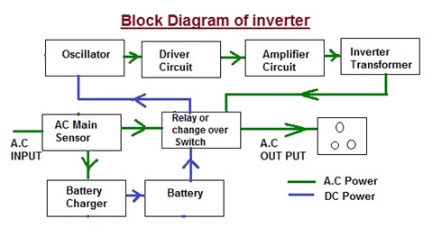
BLOCK DIAGRAM OF INVERTER:

  • Power inverter is a device that converts electrical power from DC form to AC form using electronic circuits. It is typical application is to convert battery voltage into conventional household AC voltage to use Equipments, when an AC power is not available. * There are two methods, in which the low voltage DC power is inserted into AC Power. * In First Method first is the conversion of the low voltage DC power to a high voltage DC source, an then It is the conversion of the high DC source to an AC waveform using pulse width modulation. * In Second method the outcome would be to first convert the low voltage DC power to AC, and then use a transformer to boost the voltage to 220 volts. * The widely used method in the current residential inverter is the second. * An Inverter not only converts the DC Voltage of battery to 220V V AC Signals but also charge the Battery when the AC mains are present. * The block diagram shown above is a simple depiction of the way an Inverter Works.

When the AC mains power supply is available.

  • When the Utility Company AC mains supply is available. * C Main Sensor: the AC sensor senses it and the 230V A.C supply feeds to the Relay and battery charger. * Relay or Change over Switch: AC main sensor activates a relay and this relay will directly pass the 230V AC mains supply to the Load. * Battery Charger: Battery Charger converts line A.C Voltage to DC Voltage and Charges the Battery even when A.C Power is available. * Battery: Battery is charged and it is stopped when it is full charged.

 When the AC mains power supply is not available.

  • When the AC mains power supply is not available. * Relay or Change over Switch: AC main sensor activates a relay and this relay will connected to battery in absent of the AC mains supply. * Battery: Battery is providing DC Power to Oscillator circuit through Relay. * Oscillator Circuit: An oscillator circuit inside the inverter use pulse width modulator to generate the 50Hz frequency required to generate AC supply by the inverter. * The battery DC supply is connected to the Oscillator. The flip-flop converts the incoming signal into signals with changing polarity such that in a two-signal with changing polarity. * The first is positive while the second is negative and vice versa. This process is repeated 50times per second to give an alternating signal with 50Hz frequency. This alternating signal is known as “MOS Drive Signal “. * Driver Circuit: The MOS drive signals are given to the base of driver transistor which separated into two different channels. * Amplifier Circuit: The transistors amplify the 50Hz MOS drive signal at their base to a sufficient level and output them from the emitter. * Inverter Transformer: The transformer used for this is a center-tapping which divides the primary into two equal sections. * This center-tapping is connected to the positive terminal of the battery. Two ends of the primary are connected to the negative terminal of the battery through switches S1 and S2. * MOSFETs or Transistors are used for the switching operation. These MOSFETs or Transistors are connected to the primary winding of the inverter transformer. * When these switching devices receive the MOS drive signal from the driver circuit, they start switching between ON & OFF states at a rate of 50 Hz. This switching action of the MOSFETs or Transistors creates a 50Hz current to the primary of the inverter transformer. This results in a 220V AC or 2300V AC (depending on the winding ratio of the inverter transformer) at the secondary or the inverter transformer. This secondary voltage is made available at the output socket of the inverter by a changeover relay.

 TYPE OF INVERTER

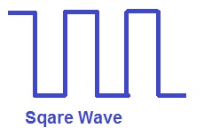
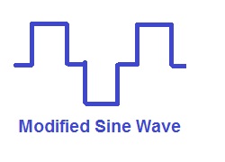
  • The inverters are classified by depending on their output * Sine wave * Modified sine wave * Square wave.

(1) SINE WAVE INVERTER:

  • In utility Company Sine wave generated by rotating AC machinery and sine waves is a natural product of rotating AC machinery. * Pure sine wave inverters provide an output same as a sine wave which is similar to the utility supplied grid power, hence Pure Sine Wave inverter produces a better and cleaner current

  • All commercial instruments are designed to run on pure sine…

J

Selection of Various Types of Inverter-(Part-2)

SELECTION OF VARIOUS TYPES OF INVERTER-(PART-2)

COMPARISON OF INVERTERS: 

Comparison of Different Type of Inverter

Square Wave Stepped Sine Wave Pure Sine Wave Safety of Appliances Less Moderate High Life of Appliances Less Moderate High Battery Life Less Moderate High Noise Level High Moderate Normal Heat generation High Low Normal Suitability for appliances No Not recommended for prolonged use Yes

HOW TO SELECT BATTERIES FOR INVERTER

  • Batter is the vital part of inverter. Performance and life of an inverter is greatly depends upon battery. * There are three types of batteries available in market.
  1. Flat Plate (Lead Acid ) Battery, 2. Tubular Battery 3. Maintenance Free Battery.
  • Without getting too much into details, all we can say is that Tubular Batteries are the best choice for inverters. They may cost slightly more than Flat Plate, but they will last longer. * Maintenance Free batteries may sound good, but they have lesser life (4-5 years as compared to 7-8 years of a tubular battery). * But the most important thing to run batteries for a longer time is to make sure that it is topped (filled) with distilled or RO water frequently and the fluid levels are maintained.

(1) LEAD ACID BATTERY

  • Lead acid batteries known as “Automotive Battery”. * Lead-acid batteries are the oldest type of rechargeable battery. Most of the inverters batteries are lead acids battery of different types. * It is used for automotive purpose are termed as “High Cycle” lead acid batteries. * These batteries are designed to provide high current for a very short duration (To start the vehicles).

1.jpg

  • Automotive lead acid batteries are not designed to be regularly discharged by more than 25% of their rated capacity. Here the requirement of inverter is totally different. * Inverter requires “Deep Cycle” type batteries to provide continuous power which can be discharged at least 50% of their rated capacity. * Some good deep cycle batteries can be discharged over 80% of their capacity. Deep Cycle batteries have specially designed thick plates to withstand frequent charging and discharging. * Lead acid batteries require regular maintenance. You have to check the electrolyte level and require to be topped up on regular intervals. These batteries release poisonous gases during charging and discharging. If you don’t keep the batteries in a properly ventilated place, it can invite serious health problems. * We have to keep the terminals of normal lead acid batteries corrosion free by applying petroleum jelly or grease regularly.

Advantage:

  • This light weighed inverter battery. * Price is Economical and quite cost-effective * This is the most common type of inverter battery. * It is a rechargeable and generates a large amount of current. * Battery life is approximately 3-4 years.

Disadvantage:

  • We need maintain it regularly, such checking the electrolyte level, topping up with distilled water etc. * Need well-ventilated place while installing a lead acid inverter battery. * Not Safer in use.

Application:

  • Suitable for small domestic Inverter.

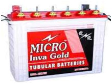
(2) TUBULAR BATTERY

  • This is the most popular and efficient among all types of inverter batteries. * Together with robust grid design, superb efficiency, long operational life and requirement of low maintenance tubular inverter battery is the most preferable choice of all.

1

  • This is the most popular segment of inverter batteries used in domestic and industrial applications.

Advantage:

  • Long life (5 Years) * High electrical efficiency. * Less Maintenance (Less number of water toppings)

Disadvantage:

  • Cost of tubular batteries can go up to double of a normal flat plate battery

Application:

  • Suitable for both domestic and industrial Inverter.

 (3) MAINTENANCE FREE BATTERY

  • As the name indicates there is no need of maintaining the batteries. No need of filling distilled water at regular intervals. This is possible because of a special type of electrolyte which need not be replenished. * Maintenance free batteries also called as sealed batteries and do not need any regular maintenance to function impeccably. * Apart from that other best feature is safety. Maintenance free batteries do not emit any poisonous or harmful gases.

1

Advantage:

  • It is costlier, But the money is worth to invest. * It is sealed lead acid batteries which do not require topping up or additional ventilation * They are more durable and safer than normal lead acid inverter battery.

Disadvantage:

  • Cost is very high as compared with normal lead acid batteries. * Life is comparatively low (3 To 4 Years) * Scrap value is not much more.

Application:

 COMPARISON OF VARIOUS TYPES OF BATTERIES 

Comparison of various types of Batteries Flat Plate Batteries Tubular Batteries Maintenance Free Batteries 1

1 - Copy

1 - Copy (2)

Cost Low High High Safety Low Low High Efficienc…
Selection of Various Types of Inverter-(Part-3)

SELECTION OF VARIOUS TYPES OF INVERTER-(PART-3)

HOW TO SELECT RIGHT INVERTER

  • Before buying an inverter for, It is very important to understand what is the right inverter for our requirement for that we do understand the basics criteria of Inverter. * In order to make a good estimate of your power needs, you’ll need to take a look at all of the devices you plan on plugging into your new inverter. * If we only need to use one device at a time, then that’s the only one you’ll need to look at. However, you’ll need to add together the numbers from multiple devices (like an LCD screen and a video game system) if you plan on using them at the same time.

(A) POWER REQUIREMENT:

  • One of the most important factors that we must know before buying an inverter is Power requirement. * Power requirement means all electrical appliances (like fan, tube lights, television,Pumps, CFL etc.), we want to run at the time of power failure. The power requirement is simply addition of the power consumed by various electrical equipments. * The thing we must understand that Inverter is not a Generator. Inverter has its own limitations. If power requirement is more than our estimation, then an inverter alone cannot create demands effectively. * High power inverter can run our refrigerator and air conditioners, but battery will not last more than few hours. Hence it better to estimate Inverter Load Carefully * The selection of correct size Inverter is very important, If we need to power small appliances like energy efficient light bulbs, we do not need to buy a 2000W power inverter because it will consume more power even in standby mode and work very inefficiently with small appliances. On the other hand, if we connect a coffee machine to a 150W inverter we will quickly blow a fuse, Therefore power estimation is important thing. * The size of Inverter depends on the watts (or amps) of what we want to run. It is recommend that we choose at least 10% to 20% more than our requirement. * Suppose you want 1No Fans, 1No Tube lights, 1No CFL and 1No television to operate at the time of power failure. Therefore the total power requirement to be (1×90 + 1×50 + 1×25 + 1×120) = 285 watts. Here Total Load is 285 watts.

(B) SURGE POWER (STARTING POWER):

  • Starting and running power requirement of all electric appliances are different. * Starting power of Electrical Equipment is several times greater than their normal working power. * An 18 Watts CFL takes around 25 Watts power to start and after few seconds it works on 18 Watts. Some appliances like Refrigerator, Washing Machine etc take almost double power to start as compared to the normal running power. * For example Gridding Machine have normal working power 1000W, their starting power is higher than 4000W, so inverters with continuous power 2000W are not suitable because their peak power is limited by 4000W. * For selecting right Inverter, Always take into account starting power requirements of your equipment, especially devices with electric motors, Electronics Choke, Capacity, inductive * The Size of the inverter should be chosen based on the power consumption of your load. * Resistive loads: All resistive loads like toaster, coffee maker, electric range, iron, Incandescent lamps, flood lighting. Laser Printers use Nichrome resistance wire in their heating * The Starting Power or Surge Power rating should be 6 times the Watt rating * Inductive Loads: All Inductive Load like induction motor, reciprocating pumps and compressors, refrigeration, air-conditioning, Oxygen Concentrators have more starting current. * The Starting current (LRA) should be 5 times the full load current (FLA). * Capacitive Loads: Switched Mode Power Supplies (SMPS), electronic equipment like battery chargers, computers, audio and video devices, radio etc. * The Starting Power or Surge Power rating should be 3 times the Watt rating * Microwaves : * The Initial power consummation by the microwave will be 2 times the cooking power. * A Water Supply Pump: * The starting surge can be 3 times the normal running rating of the pump * The inverter should, therefore, be sized adequately to withstand the high inrush current. 

 Starting Factor

Type of Device Starting Factor Air conditioner 5 Refrigerator / Freezer 5 Air Compressor 4 Sump Pump / Well Pump / Submersible Pump 3 Dishwasher 3 Clothes Washer 3 Microwave 2 Furnace Fan 3 Industrial Motor 3 Portable Kerosene / Diesel Fuel Heater 3 Circular Saw 3 Bench Grinder 3 Incandescent / Halogen / Quartz Lamps 3 Laser Printer / Other Devices using Quartz Lamps for heating 4 Switched Mode Power Supplies 3 Photographic Strobe / Flash Lights 4

(C) RATING (VA RATING) OF THE INVERTER:

  • It stands for the Volt ampere rating. It is the voltage and current supplied by the inverter to the equipments. * If an inverter operates with 100% efficiency, then the power requirement of th…
J

Selection of Various Types of UPS (Part-1)

SELECTION OF VARIOUS TYPES OF UPS (PART-1)

INTRODUCTION:

  • Whenever there is a power cut, electricity supply to Computer, Desktop or other critical appliances is cut off and they stop working. However, if we have a backup supply device such as UPS, we can ensure uninterrupted supply of power to appliances to be not bothered with power cuts. * Electrical power supply comes from utility companies is not pure it has different Electrical abnormalities like surges, under voltage, Over Voltage, Voltage dips, voltage spikes, Noise and harmonics. These Electrical abnormalities can cause serious damage to Electronics equipments, Data Systems, Computer or Desktop. * To decrease the risk of power supply distortion, UPS systems are frequently integrated in electrical networks. Electronic power supply equipment makers can offer consistent, high-quality power flow for various Electrical / Electronic load gear likes continuous industrial processing applications, medical services, emergency gear, telecommunications, & computerized data systems. * Today’s UPS systems usually provide some level of power conditioning and protection against fluctuations in voltage from the grid.

UPS:

  • UPS means uninterrupted power supply. * Uninterruptible power supply (UPS) provides uninterrupted power to the equipment. It means switching time from power cut to battery power is very less hence important equipment like computer, desktop is not switch off and we can lose data. * A UPS is a complete system that is consisting of many parts that include batteries, a charge controller, circuitry any transfer switch for switching between the mains and back-up battery, and an inverter. An inverter is needed because the battery can only store DC power and we need to convert that back to AC in order to match the appliances connected in the main power line. * UPS= Battery charger + Inverter * UPS is nothing but inverter with inbuilt battery charger. * UPS is used only to backup your system. If we connect desktop computer on inverter. Inverter takes some seconds to give battery power to equipment hence equipment shutdowns for some second in any power loss condition and we can lose important data of desktop or computer. * Inverter is not suitable for computer backup due to the delay in switching. * One of more useful functions of UPS is to provide surge protection so connected devices can be protected from line Surge and does not damage. UPS is also capable of conditioning the power from the lines to provide clean and stable power throughout.

BLOCK DIAGRAM OF UPS:

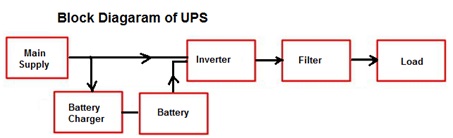
  • The block diagram of this UPS is shown as below

1

  • The mains power comes to the UPS. The AC is converted to DC and this DC is constantly charging the battery. The output of the battery is fed to the Sine wave inverter and it converts DC to AC and this feeds the equipment. Since power out is always drawn from the battery, there is no time lag when mains switches off, it just stops the battery from being charged and the UPS continues to supply power till the battery runs out. * Battery Charger (Rectifier ): To convert AC Power (from Power Grid) to DC Power to charge Battery * Battery: To provide DC Power. * Inverter: To convert DC Power (from Battery) to AC Power (to power load i.e., electrical and electronic equipment.) * Controller: To control functions of Rectifier (Charger) and Inverter. (i.e., when to start or stop charging battery, when to start or stop power from battery to load, how fast to change from Grid Power to Battery Power and so on)

 TYPE OF UPS:

  • The UPS is mainly categorized into three types according to their functions. They are as
  1. Offline Standby (where system or data loss is an inconvenience) 2. Line-interactive (system or data loss is a serious problem). 3. Online/Double Conversion (system or data loss is unacceptable).

 (1) OFF LINE UPS / STANDBY UPS:

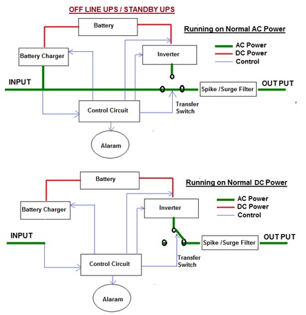
  • Off-line UPS systems are so-called “OFF Line” because load is normally connected directly to the incoming AC mains. When the incoming AC mains fails or fall below a pre-determined level, then the offline UPS turns on its internal DC-AC inverter circuitry, which is powered from an internal storage battery. * For switching purpose UPS consists mechanically / Static switches which immediately connect the load on its DC-AC inverter output under the mains power failure condition. During this changeover there is an inevitable break in power to the load of typically 2 to 10 milliseconds. In practice, however, most loads can ride through this period without any problems. * The switching process causes a momentary lapse in power which is dangerous for certain highly-sensitive equipment. This is why technically, the standby UPS is not considered a “true UPS”, as it is not truly “uninterruptible”. * The typical lapse time 5ms,is well within tolerance for normal desktop computers

 Circuit Diagram:

1

 Working…