Site logo
Electrical Engineering Academy
A

Star-Star Connection of Transformer

STAR-STAR CONNECTION OF TRANSFORMER

Transformer Connection:

The windings of three phase transformers may be connected in by Y or Δ in the same manner as for three single phase transformers. Since the secondary’s may be connected either in Y or Δ regardless of which connection is used on the primaries, there must be four ways of connecting the windings of a 3-phase transformer for transformation of 3-phase voltages, namely Y-y,Δ -Δ, Y-Δ, and Δ -y. The inter-connections are made inside of the case so that only the terminal leads need to be brought outside the case

  1. Star – Star Transformer (Yy0 or Yy6) 2. Delta – Delta Transformer (Dd0 or Dd6) 3. Delta – Star Transformer (Dy) 4. Star – Delta Transformer Yd) (Grounding Transformer). 5. Zig-zag Transformer (Yz, Dz) (Grounding Transformer) 6. Scott (“T” Type) Transformer (Grounding Transformer).

(1) STAR-STAR(Y-Y)CONNECTION:

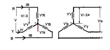
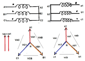
  • In Primary Winding Each Phase is120°electrical degrees out of phase with the other two phases. * In Secondary Winding Each Phase is120°electrical degrees out of phase with the other two phases. * Each primary winding is magnetically linked to one secondary winding through a common core leg. Sets of windings that are magnetically linked are drawn parallel to each other in the vector diagram. In the Y-Y connection, each primary and secondary winding is connected to a neutral point. * The neutral point may or may not be brought out to an external physical connection and the neutral may or may not be grounded.

  • Transformer magnetizing currents are not purely sinusoidal, even if the exciting voltages are sinusoidal. The magnetizing currents have significant quantities of odd-harmonic components. If three identical transformers are connected to each phase and are excited by 60 Hz voltages of equal magnitude, the 60 Hz fundamental components of the exciting currents cancel out each other at the neutral. This is because the 60 Hz fundamental currents of A, B, and C phase are 120° out of phase with one another and the vector sum of these currents is zero. * The third, ninth, fifteenth and other so-called zero-sequence harmonic currents are in phase with each other; therefore, these components do not cancel out each other at the neutral but add in phase with one another to produce a zero-sequence neutral current, provided there is a path for the neutral current to flow. * Due to the nonlinear shape of the B-H curve, odd-harmonic magnetizing currents are required to support sinusoidal induced voltages. If some of the magnetizing current harmonics are not present, then the induced voltages cannot be sinusoidal. * Y-Y Connection with Grounded Neutral : * Figure Show the situation where the primary neutral is returned to the voltage source in a four-wire three-phase circuit. Each of the magnetizing currents labeled IR, IY, and IB contain the 60 Hz fundamental current and all of the odd harmonic currents necessary to support sinusoidal induced voltages.

  • The zero-sequence magnetizing currents combine to form the neutral current IN, which returns these odd harmonics to the voltage source. Assuming that the primary voltage is sinusoidal, the induced voltages VR , VY , and VB (in both the primary and secondary) are sinusoidal as well. * The connection of primary neutral to the neutral of generator has an add advantage that it eliminates distortion in the secondary phase voltages. If the flux in the core has sinusoidal waveform then it will give sinusoidal waveform for the voltage. But due to characteristic of iron, a sinusoidal waveform of flux requires a third harmonic component in the exciting current. As the frequency of this component is thrice the frequency of circuit at any given constant. It will try to flow either towards or away from the neutral point in the transformer windings. With isolated neutral, the triple frequency current cannot flow so the flux in the core will not be a sine wave and the voltages are distorted. If primary neutral is connected to generator neutral the triple frequency currents get the path to solve the difficulty. The alternative way of overcoming with this difficulty is the use of tertiary winding of low KVA rating. These windings are connected in delta and provide a circuit in which triple frequency currents can flow. Thus sinusoidal voltage on primary will give sinusoidal voltage on secondary side. * This situation changes if the neutrals of both sets of the primary and secondary windings are not grounded. * Y-Y Connection without Grounded Neutral: If the neutrals of both the primary and the secondary are open-circuited and so there is no path for the zero-sequence harmonic currents to flow and …
A

Various Routine Test of Power Transformer-(Part-4)

VARIOUS ROUTINE TEST OF POWER TRANSFORMER-(PART-4)

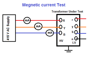
(9) MAGNETIC BALANCE TEST

 Test Purpose:

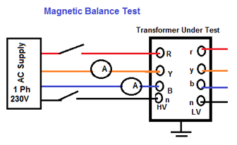
  • Magnetic balance test of transformer is conducted only on three phase transformers to check the imbalance in the magnetic circuit.

 Test Instrument:

  • Multi meter. * Mill Ammeter

 Test Circuit Diagram:

 Untitled

Test Procedure:

  • First keep the tap changer of transformer in normal position. * Now disconnect the transformer neutral from ground. * Then apply single phase 230V AC supply across one of the HV winding terminals and neutral terminal. * Measure the voltage in two other HV terminals in respect of neutral terminal. * Repeat the test for each of the three phases. * In case of auto transformer, magnetic balance test of transformer should be repeated for IV winding also. * There are three limbs side by side in a core of transformer. One phase winding is wound in one limb. The voltage induced in different phases depends upon the respective position of the limb in the core. * The voltage induced in different phases of transformer in respect to neutral terminals given in the table below. * 415V, Two phase supply is to be applied to any two phases terminals on HV side of Power transformer and voltages in other two phase combination are to be measured with LT open. * Sum of the Resultant two values shall be equal to the voltage applied.

Applied Voltage (415V) Measured Voltage(V1) Measured Voltage(V2) Result RY YB BR V=V1+V2 YB RY BR V=V1+V2 BR YB RY V=V1+V2

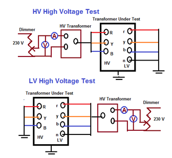
 (10) HIGH VOLTAGE TESTS ON HV & LV WINDING:

Test Purpose:

  • To checks the insulation property between Primary to earth, Secondary to earth and between Primary & Secondary.

 Test Instrument:

  • High Voltage tester ( 100KV & 3KV)

 Test Circuit Diagram:

Untitled Procedure:

  • HV high voltage test: LV winding connected together and earthed. HV winding connected together and given Following HV Supply for 1 minute. * LV high Voltage test: HV winding connected together and earthed. LV winding connected together and given Following HV Supply for 1 minute. * 433V Winding =3KV High Voltage * 11KV Winding =28KV High Voltage * 22KV Winding =50KV High Voltage * 33KV Winding =70KV High Voltage.

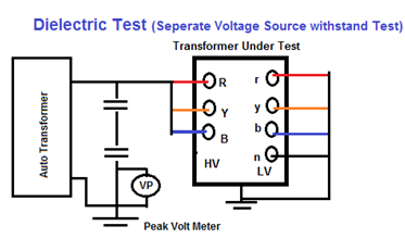
(11) DI ELECTRICAL TEST:

Test Purpose:

  • To check the ability of main insulation to earth and between winding * To checks the insulation property between Primary to earth, Secondary to earth and between Primary & Secondary.

 Test Instruments:

  • 3 Phase Variable Voltage & Frequency Source. * Auto Transformer.

 Test Procedure:

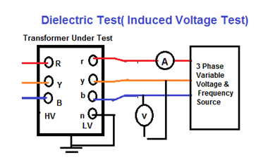
  • The following Dielectric tests are performed in order to meet the transformer insulation strength expectations. * Switching impulse test: to confirm the insulation of the transformer terminals and windings to the earthed parts and other windings, and to confirm the insulation strength in the windings and through the windings. * Lightning impulse test : to confirm the transformer insulation strength in case of a lightning hitting the connection terminals * Separate source AC withstand voltage test: to confirm the insulation strength of the transformer line and neutral connection terminals and the connected windings to the earthed parts and other windings. * Induced AC voltage test (short duration ACSD and long duration ACLD ) : to confirm the insulation strength of the transformer connection terminals and the connected windings to the earthed parts and other windings, both between the phases and through the winding. * Partial discharge measurement: to confirm the “partial discharge below a determined level” property of the transformer insulation structure under operating conditions.

 Method No 1 (separate source voltage withstand test) Untitled

  • All the terminals of the winding under test should be connected together and the voltage should be applied. * The secondary windings of bushing type current transformers should be connected together and earthed. The current should be stable during test and no surges should occur. * A single phase power frequency voltage of shape approximately sinusoidal is applied for 60 seconds to the terminals of the winding under test. * The test shall be performed on all the windings one by one. * The test is successful if no breakdown in the dielectric of the insulation occurs during test. * During the Separate source AC withstand voltage test, the frequency of the test voltage should be equal to the transformer’s rated frequency or should be not less than 80% of this frequency. In this way, 60 Hz transformers can also be tested at 50 Hz. The shape of the voltage should be single phase and sinusoidal as far as possible. * This test is applied to the star point …
A

Various Routine Test of Power Transformer-(Part-3)

VARIOUS ROUTINE TEST OF POWER TRANSFORMER-(PART-3)

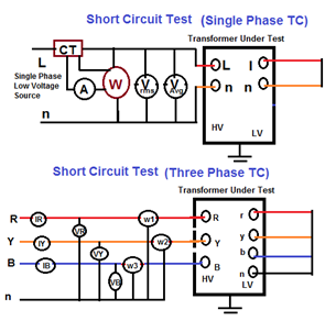
(5) SHORT CIRCUIT TEST

 Test Purpose:

  • The value of the short circuit impedance Z% and the load (copper) losses (I2R) are obtained. * This test should be performed before the impulse test-if the later will be performed as a routine test- in order to avoid readings errors

 Test Instrument:

  • Megger or * Multi meter. * CT ,PT

 Test Procedure:

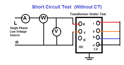
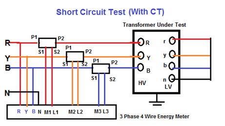
  • Suitable Low Voltage (3-phase 415V, 50Hz )will be applied to the terminals of one winding (usually the H.V.) with the other winding short circuited with 50 sq. mm. Copper cable. (Usually the L.V.) * The applied voltage is adjusted to pass the needed current in the primary/secondary. In order to simulate conditions nearest to full load, it is customary to pass 100%, 50% or at least 25% of full load current. * Voltage to be increased gradually till the current in the energized winding reaches the required value (50% to 100% rated current). * Measure the 3 Phase line currents at all tap position. If the tap-switch is an Off-Circuit tap-switch, the supply has to be disconnected before changing the tap. A consistent trend in the increase or decrease of current, as the case may be, confirms the healthiness of the transformer. * If transformer is equipped with a tap changer, tapping regulations are applied. * (1) If tapping range within±5% and rated power less than 2500kAV, load loss guarantee refer to the principal tap only. * (2) If tapping range exceeds±5% or rated power above 2500kAV, it shall be stated for which tapping beside the principal tap the load losses will be guaranteed by the manufacturer. * Three phase LT supply is applied on HV side of power transformer at normal tap with rated current on HV side and currents measured in all the phases on HV side and phases & neutral on LV side values noted. * Readings to be taken as quickly as possible as the windings warm up and the winding resistance increases. Hence, the losses value will increase accordingly. * Using appropriate instruments (conventional three watt meter method or digital watt meter with ammeters & voltmeters) measurements of voltage, currents and power can be recorded.

 Untitled

  • Short Circuit Test (Without using CT,PT) * To avoid CT’s and PT’s, this method can be used at current levels of 2 to 5 A and measurement of load losses is done at this condition. This measured load loss is then extrapolated to actual load currents to obtain load losses at the operating current. * Example: – 11 kV/433 V, 1000 kVA transformer with 5% impedance, the voltage to be applied on H.V. side during load test is estimated below. * V. side full load current (I1) = (KVAx1000/1.732xLine Voltage) * V. side full load current (I1) =(1000×1000/1.732×11000)=52.5 Amp * Line to line voltage to be applied on H.V side for getting 5 A on H.V. side, * Line to line voltage to be applied on H.V side Visc= (Line Voltagex1000xZx5/0.866xI1x100) * Line to line voltage to be applied on H.V side Visc=(11x1000x5xx/x0.866×52.5×100)=60.5 volts. * Since the current drawn on H.V. side is only about 5A in this test, CT’s can be avoided and hence phase angle error is not applicable.

Untitled

  • Short Circuit Test (With using CT,PT)

 Untitled Criteria:

  • Measured impedance to be within guaranteed value and nameplate value. * Load losses to be within guaranteed values.

 Test can detect:

  • Winding deformation. * Deviation in name plate value.

 (6) OPEN CIRCUIT / NO LOAD TEST

 Test Purpose:

  • In this test, the value of No-Load power (Po) & the No-Load current (Io) are measured at rated voltage & frequency.

 Test Instruments:

  • Watt meters. * Ammeter , Voltmeter or * Power analyses

 Test Procedure:

  • Test is performed at rated frequency. * Three phase LT Voltage of 415 V applied on HV side of Power transformer keeping LT open * Two voltmeters are connected to the energized winding, one is measuring the voltage mean value and the other is for the Voltage R.M.S value. * Voltage applied to winding (usually to H.V. windings).It will be in a range from 90% of winding rated voltage to 110% of the same in steps, each of 5% (i.e. for a 33/11kV transformer, applied voltage values will be 29.7kV, 31.35kV,36.3kV) * Readings of watt meters, Voltmeters & Ammeters are recorded to obtain the values of V (r.m.s), Vmean, Po and Io at each voltage step. * Test results are considered satisfactory if the readings of the two are equal within 3%. If it’s more than 3%, the validity of the test is subjected to agreement. * Measured value of power loss is corrected according to the following formula: * Pc=Pm (1+d) * D= (Vmean – Vr.m.s) / Vmean * Measure the…
A

Various Routine Test of Power Transformer-(Part-2)

VARIOUS ROUTINE TEST OF POWER TRANSFORMER-(PART-2)

(3) TURNS RATIO / VOLTAGE RATIO TEST:

 Test Purpose:

  • Turns Ratio Test / Voltage Ratio Test are done in Transformer to find out Open Circuited turns, Short Circuited turns in Transformer winding. * The voltage ratio is equal to the turn’s ratio in a transformer (V1/V2=N1/N2). Using this principle, the turn’s ratio is measured with the help of a turn’s ratio meter. If it is correct , then the voltage ratio is assumed to be correct * This test should be made for any new high-voltage power transformer at the time it is being installed. * With use of Turns Ratio meter (TTR), turns Ratio between HV & LV windings at various taps to be measured & recorded. * The turn’s ratio is measure of the RMS voltage applied to the primary terminals to the RMS Voltage measured at the secondary terminals. * R= Np / Ns * Where, * R=Voltage ratio * Np=Number of turns at primary winding. * Ns= Number of turns at secondary Winding. * The voltage ratio shall be measured on each tapping in the no-load condition.

 Test Instruments:

  • Turns Ratio meter (TTR) to energies the transformer from a low-voltage supply and measure the HV and LV voltages. * Wheatstone Bridge Circuit

 METHOD NO1 TURNS RATIO TESTING:

 Test Procedure:

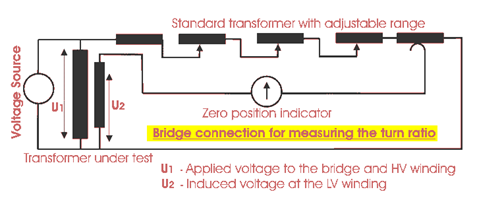
  • Transformer Turns Ratio Meter (TTR): * Transformer ratio test can be done by Transformer Turns Ratio (TTR) Meter. It has in built power supply, with the voltages commonly used being very low, such as 8, 10 V and 50 Hz. * The HV and LV windings of one phase of a transformer (i.e. R-Y & r-n) are connected to the instrument, and the internal bridge elements are varied to produce a null indication on the detector. * Values are recorded at each tap in case of tapped windings and then compared to calculated ratio at the same tap. * The ratio meter gives accuracy of 0.1 per cent over a ratio range up to 1110:1. The ratio meter is used in a ‘bridge’ circuit where the voltages of the windings of the transformer under test are balanced against the voltages developed across the fixed and variable resistors of the ratio meter. * Adjustment of the calibrated variable resistor until zero deflection is obtained on the galvanometer then gives the ratio to unity of the transformer windings from the ratio of the resistors. * Bridge Circuit:

Untitled

  • A phase voltage is applied to the one of the windings by means of a bridge circuit and the ratio of induced voltage is measured at the bridge. The accuracy of the measuring instrument is < 0.1 % * This theoretical turn ratio is adjusted on the transformer turn ratio tested or TTR by the adjustable transformer as shown in the figure above and it should be changed until a balance occurs in the percentage error indicator. The reading on this indicator implies the deviation of measured turn ratio from expected turn ratio in percentage. * Theoretical Turns Ratio = HV winding Voltage / LV Winding Voltage * % Deviation = (Measured Turn Ratio – Expected Turns Ration) / Expected Turns Ration * Out-of-tolerance, ratio test of transformer can be due to shorted turns, especially if there is an associated high excitation current. * Open turns in HV winding will indicate very low exciting current and no output voltage since open turns in HV winding causes no excitation current in the winding means no flux hence no induced voltage. * But open turn in LV winding causes, low fluctuating LV voltage but normal excitation current in HV winding. Hence open turns in LV winding will be indicated by normal levels of exciting current, but very low levels of unstable output voltage. * The turn ratio test of transformer also detects high resistance connections in the lead circuitry or high contact resistance in tap changers by higher excitation current and a difficulty in balancing the bridge.

 Test Caution:

  • Disconnect all transformer terminals from line or load. * Neutrals directly grounded to the grid can remain connected

 METHOD NO 2 VOLTAGE RATIO TESTING:

  • This test is done to check both the transformer voltage ratio and tap changer. * When “Turns Ratio meter” is not available, Voltage Ratio Test is done at various tap position by applying 3 phases LT (415V) supply on HT side of Power transformer. In order to obtain the required accuracy it is usual to use a ratio meter rather than to energies the transformer from a low-voltage supply and measure the HV and LV voltages. * At Various taps applied voltage and Resultant voltages LV side between various Phases and phases& neutral measured with precision voltmeter & noted.

 Test Procedure:

  • With 415 V applied on high voltage side, measure the voltage between all phases on the low voltage side for every tap position. * First, the tap changer of transformer is kept in the lowest position and LV terminals are ke…
A

Various Routine Test of Power Transformer-(Part-1)

VARIOUS ROUTINE TEST OF POWER TRANSFORMER-(PART-1)

INTRODUCTION:

  • There are various Test required on Transformer to conform performance of Transformer. * Mainly two types of transformer are done by manufacturer before dispatching the transformer mainly (1) Type test of transformer and (2) Routine test. * In addition some other tests are also carried out by the consumer at site before commissioning and also periodically in regular & emergency basis throughout its life. * Transformer Testing mainly classified in * Transformer Tests done by Manufacturer * (A) Routine Tests * (B)Type Tests * (C) Special Tests * Transformer Tests done at Site * (D) Pre Commissioning Tests * (E) Periodic/Condition Monitoring Tests * (F) Emergency Tests

(A) Routine tests:

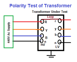
  • A Routine test of transformer is mainly for confirming operational performance of individual unit in a production lot. Routine tests are carried out on every unit manufactured. * All transformers are subjected to the following Routine tests: * Insulation resistance Test. * Winding resistance Test. * Turns Ration / Voltage ratio Test * Polarity / Vector group Test. * No-load losses and current Test. * Short-circuit impedance and load loss Test. * Continuity Test * Magnetizing Current Test * Magnetic Balance Test * High Voltage Test. * Dielectric tests * Separate source AC voltage. * Induced overvoltage. * Lightning impulse tests. * Test on On-load tap changers, where appropriate.

 (B) Type tests

  • Type tests are tests made on a transformer which is representative of other transformers to demonstrate that they comply with specified requirements not covered by routine tests: * Temperature rise test (IEC 60076-2). * Dielectric type tests (IEC 60076-3).

 (C) Special tests

  • Special tests are tests, other than routine or type tests, agreed between manufacturer and purchaser. * Dielectric special tests. * Zero-sequence impedance on three-phase transformers. * Short-circuit test. * Harmonics on the no-load current. * Power taken by fan and oil-pump motors. * Determination of sound levels. * Determination of capacitances between windings and earth, and between windings. * Determination of transient voltage transfer between windings. * Tests intended to be repeated in the field to confirm no damage during shipment, for example frequency response analysis (FRA).

(D) Pre commissioning Tests

  • The Test performed before commissioning the transformer at site is called pre commissioning test of transformer. These tests are done to assess the condition of transformer after installation and compare the test results of all the low voltage tests with the factory test reports. * All transformers are subjected to the following Pre commissioning tests: * IR value of transformer and cables * Winding Resistance * Transformer Turns Ratio * Polarity Test * Magnetizing Current * Vector Group * Magnetic Balance * Bushing & Winding Tan Delta (HV ) * Protective relay testing * Transformer oil testing * Hipot test

 (A) ROUTINE TESTS OF TRANSFORMER

(1) INSULATION RESISTANCE TEST:

 Test Purpose:

  • Insulation resistance test of transformer is essential to ensure the healthiness of overall insulation of an electrical power transformer.

 Test Instruments:

  • For LT System: Use 500V or 1000V Megger. * For MV / HV System: Use 2500V or 5000V Megger.

 Test Procedure:

  • First disconnect all the line and neutral terminals of the transformer. * Megger leads to be connected to LV and HV bushing studs to measure Insulation Resistance (IR) value in between the LV and HV windings. * Megger leads to be connected to HV bushing studs and transformer tank earth point to measure Insulation Resistance IR value in between the HV windings and earth. * Megger leads to be connected to LV bushing studs and transformer tank earth point to measure Insulation Resistance IR value in between the LV windings and earth. * NB: It is unnecessary to perform insulation resistance test of transformer per phase wise in three phase transformer. IR values are taken between the windings collectively as because all the windings on HV side are internally connected together to form either star or delta and also all the windings on LV side are internally connected together to form either star or delta. * Measurements are to be taken as follows:

Type of Transformer Testing-1 Testing-2 Testing-3 Auto Transformer HV-LV to LV HV-IV to E LV to E Two Winding Transformer HV to LV HV to E LV to E Three Winding Transformers HV to LV LV to LV HV to E & LV to E

  • Oil temperature should be noted at the time of insulation resistance test of transformer. Since the IR value of transformer insulating oil may vary with temperature. * IR values to be recorded at intervals of 15 seconds, 1 minute and 10 minutes. * With the duration of application of voltage, IR value increases. The increase in IR is an indication of dryness of in…
A

Abstract of over current Protection of Transformer (NEC 450.3)

ABSTRACT OF OVER CURRENT PROTECTION OF TRANSFORMER (NEC 450.3)

INTRODUCTION:

  • The over current protection required for transformers is consider for Protection of Transformer only.Such over current protection will not necessarily protect the primary or secondary conductors or equipment connected on the secondary side of the transformer. * When voltage is switched on to energize a transformer, the transformer core normally saturates. This results in a large inrush current which is greatest during the first half cycle (approximately0.01 second) and becomes progressively less severe over the next several cycles (approximately 1 second) until the transformer reaches its normal magnetizing current. * To accommodate this inrush current, fuses are often selected which have time-current withstand values of at least 12 times transformer primary rated current for 0.1 second and 25 times for 0.01 second. Some small dry-type transformers may have substantially greater inrush currents. * To avoid using over sized conductors, over current devices should be selected at about 110 to 125 percent of the transformer full-load current rating. And when using such smaller over current protection, devices should be of the time-delay type (on the primary side) to compensate for inrush currents which reach 8 to 10 times the full-load primary current of the transformer for about 0.1 s when energized initially. * Protection of secondary conductors has to be provided completely separately from any primary-side protection. * A supervised location is a location where conditions of maintenance and supervision ensure that only qualified persons will monitor and service the transformer installation. * Over current protection for a transformer on the primary side is typically a circuit breaker. In some instances where there is not a high voltage panel, there is a fused disconnect instead. * It is important to note that the over current device on the primary side must be sized based on the transformer KVA rating and not sized based on the secondary load to the transformer

OVER CURRENT PROTECTION OF TRANSFORMERS > 600 V (NEC 450.3-A)

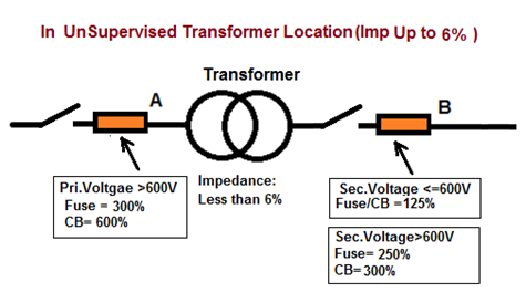
 1) UNSUPERVISED LOCATION OF TRANSFORMER (IMPEDANCE <6%)

  • Over Current Protection at Primary Side (Primary Voltage >600V): * Rating of Pri. Fuse at Point A= 300% of Pri. Full Load Current or Next higher Standard size. or * Rating of Pri. Circuit Breaker at Point A= 600% of Pri. Full Load Current or Next higher Standard size. * Over Current Protection at Secondary Side (Secondary Voltage <=600V): * Rating of Sec. Fuse / Circuit Breaker at Point B= 125% of Sec. Full Load Current or Next higher Standard size. * Over Current Protection at Secondary Side (Secondary Voltage >600V): * Rating of Sec. Fuse at Point B= 250% of Sec. Full Load Current or Next higher Standard size. or * Rating of Sec. Circuit Breaker at Point B= 300% of Sec. Full Load Current.

Example: 750KVA, 11KV/415V 3Phase Transformer having Impedance of Transformer 5%

  • Full Load Current At Primary side=750000/(1.732X11000)=39A * Rating of Primary Fuse = 3X39A= 118A, So Standard Size of Fuse =125A. * OR Rating of Primary Circuit Breaker =6X39A=236A, So Standard Size of Circuit Breaker =250A. * Full Load Current at Secondary side=750000/ (1.732X415) =1043A. * Rating of Secondary of Fuse / Circuit Breaker = 1.25X1043A=1304A, So Standard Size of Fuse =1600A.

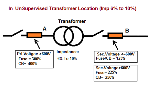
 2) UNSUPERVISED LOCATION OF TRANSFORMER (IMPEDANCE 6% TO 10 %)

  • Over Current Protection at Primary Side (Primary Voltage >600V): * Rating of Pri. Fuse at Point A= 300% of Primary Full Load Current or Next higher Standard size. * Rating of Pri. Circuit Breaker at Point A= 400% of Primary Full Load Current or Next higher Standard size. * Over Current Protection at Secondary Side (Secondary Voltage <=600V): * Rating of Sec. Fuse / Circuit Breaker at Point B= 125% of Sec. Full Load Current or Next higher Standard size. * Over Current Protection at Secondary Side (Secondary Voltage >600V): * Rating of Sec. Fuse at Point B= 225% of Sec. Full Load Current or Next higher Standard size. * Rating of Sec. Circuit Breaker at Point B= 250% of Sec. Full Load Current or Next higher Standard size.

Example: 10MVA, 66KV/11KV 3Phase Transformer, Impedance of Transformer is 8%

  • Full Load Current At Primary side=10000000/(1.732X66000)=87A * Rating of Pri. Fuse = 3X87A= 262A, So Next Standard Size of Fuse =300A. * OR Rating of Pri. Circuit Breaker =4X87A=348A, So Next Standard Size of Circuit Breaker =400A. * Full Load Current at Secondary side=10000000/ (1.732X11000) =525A. * Rating of Sec. Fuse = 2.25X525A=1181A, So Next Standard Size of Fuse =1200A. * OR Rating of Sec. Circuit Breaker =2.5X525A=1312A, So Next Standard Size of Circuit Breaker =1600A.

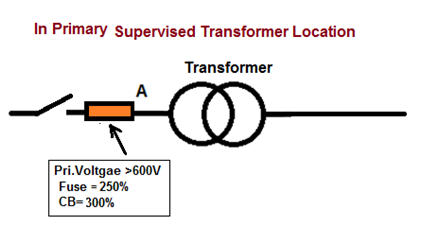
 3) SUPERVISE…

Electrical Safety Clearance for Transformer

ELECTRICAL SAFETY CLEARANCE FOR TRANSFORMER

ELECTRICAL SAFETY CLEARANCE FOR TRANSFORMER:

 CLEARANCE FROM OUTDOOR LIQUID INSULATED TRANSFORMERS TO BUILDINGS (NEC):

Liquid Liquid Volume (m3) Fire Resistant Wall Non-Combustible Wall Combustible Wall Vertical Distance Less Flammable NA 0.9 Meter 0.9 Meter 0.9 Meter 0.9 Meter <38 m3 1.5 Meter 1.5 Meter 7.6 Meter 7.6 Meter >38 m3 4.6 Meter 4.6 Meter 15.2 Meter 15.2 Meter Mineral Oil <1.9 m3 1.5 Meter 4.6 Meter 7.6 Meter 7.6 Meter 1.9 m3 to 19 m3 4.6 Meter 7.6 Meter 15.2 Meter 15.2 Meter > 19 m3 7.6 Meter 15.2 Meter 30.5 Meter 30.5 Meter

 CLEARANCE BETWEEN TWO OUTDOOR LIQUID INSULATED TRANSFORMERS (NEC):

Liquid Liquid Volume (m3) Distance Less Flammable NA 0.9 Meter <38 m3 1.5 Meter >38 m3 7.6 Meter Mineral Oil <1.9 m3 1.5 Meter 1.9 m3 to 19 m3 7.6 Meter > 19 m3 15.2 Meter

 DRY TYPE TRANSFORMER IN INDOOR INSTALLATION (NES 420.21):

Voltage

Distance (min) Up to 112.5 KVA 300 mm (12 in.) from combustible material unless separated from the combustible material by a heat-insulated barrier. Above 112.5 KVA Installed in a transformer room of fire-resistant construction. Above 112.5 KVA with Class 155 Insulation separated from a fire-resistant barrier not less than 1.83 m (6 ft) horizontally and 3.7 m (12 ft) vertically

 DRY TYPE TRANSFORMER IN OUTDOOR INSTALLATION (NES 420.22):

Voltage

Distance (min) Above 112.5 KVA with Class 155 Insulation separated from a fire-resistant barrier not less than 1.83 m (6 ft) horizontally and 3.7 m (12 ft) vertically

 NON FLAMMABLE LIQUID-INSULATED TRANSFORMER IN INDOOR INSTALLATION (NES 420.21):

Voltage

Distance (min) Over 35KV Installed indoors Vault (Having liquid confinement area and a pressure-relief vent for absorbing any gases generated by arcing inside the tank, the pressure-relief vent shall be connected to a chimney or flue that will carry such gases to an environmentally safe area Above 112.5 KVA Installed in a transformer room of fire-resistant construction. Above 112.5 KVA (Class 155 Insulation) separated from a fire-resistant barrier not less than 1.83 m (6 ft) horizontally and 3.7 m (12 ft) vertically

 OIL INSULATED TRANSFORMER IN INDOOR INSTALLATION (NES 420.25):

Voltage

Distance (min)

Up to 112.5 KVA

Installed indoors Vault (With construction of reinforced concrete that is not less than 100 mm (4 in.) thick.

Up to 10 KVA & Up to 600V

Vault shall not be required if suitable arrangements are made to prevent a transformer oil fire from igniting

Up to 75 KVA & Up to 600V

Vault shall not be required if where the surroundingStructure is classified as fire-resistant construction. Furnace transformers (Up to 75 kVA) Installed without a vault in a building or room of fire resistant construction

 TRANSFORMER CLEARANCE FROM BUILDING (IEEE STAND):

Transformer

Distance from Building (min) Up to 75 KVA

3.0 Meter

75 KVA to 333 KVA

6.0 Meter

More than 333 KVA

9.0 Meter

 TRANSFORMER CLEARANCE SPECIFICATIONS (STAND: GEORGIA POWER COMPANY):

Description of Clearance

Distance (min)

Clearance in front of the transformer

3.0 Meter

Between Two pad mounted transformers (including Cooling fin)

2.1 Meter

Between Transformer and Trees, shrubs, vegetation( for unrestricted natural cooling )

3.0 Meter

The edge of the concrete transformer pad to nearest the building

4.2 Meter

The edge of the concrete transformer pad to nearest building wall, windows, or other openings

3.0 Meter

Clearance from the transformer to edge of (or Canopy) building (3 or less stories)

3.0 Meter

Clearance in front of the transformer doors and on the left side of the transformer, looking at it from the front. (For operation of protective and switching devices on the unit.)

3.0 Meter

Gas service meter relief vents.

0.9 Meter

Fire sprinkler values, standpipes and fire hydrants

1.8 Meter

The water’s edge of a swimming pool or any body of water.

4.5 Meter

Facilities used to dispense hazardous liquids or gases

6.0 Meter

Facilities used to store hazardous liquids or gases

3.0 Meter

Clear vehicle passageway at all times, immediately adjacent of Transformer

3.6 Meter

Fire safety clearances can be reduced by building a suitable masonry fire barrier wall (2.7 Meter wide and 4.5 Meter Tall) 0.9 Meter from the back or side of the Pad Mounted Transformer to the side of the combustible wall

Front of the transformer must face away from the building.

CLEARANCE OF TRANSFORMER-CABLE-OVERHEAD LINE (STAND: GEORGIA POWER COMPANY):

Description of Clearance

Horizontal Distance (mm)

to pad-mounted transformers

to buried HV cable

to overhead HV Line

Fuel tanks

7.5 Meter

1.5 Meter

7.5 Meter

Granaries

6.0 Meter

0.6 Meter

15 Meter

Homes

6.0 Meter

0.6 Meter

15 Meter

Barns, sheds, garages

6.0 Meter

0.6 Meter

15 Meter

Water wells

1.5 Meter

1.5 Meter

15 Meter

Antennas

3.0 Meter

0.6 Meter

Height of Antenna + 3.0 Meter

Abstract of National Electrical Code for Transformer’s Protection

ABSTRACT OF NATIONAL ELECTRICAL CODE FOR TRANSFORMER’S PROTECTION

ABSTRACT OF NATIONAL ELECTRICAL CODE FOR TRANSFORMER’S PROTECTION:

NEC, CODE 450.4: (CALCULATE OVER CURRENT PROTECTION ON THE PRIMARY)

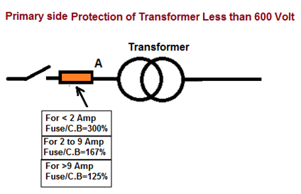
  • According to NEC 450.4, “each transformer 600 volts, nominal, or less shall be protected by an individual over current device installed in series with each ungrounded input conductor. * Such over current device shall be rated or set at not more than 125% of the rated full-load input current of the auto transformer. * Further, according to NEC Table 450.3(B), if the primary current of the transformer is less than 9 amps, an over current device rated or set at not more than 167% of the primary current shall be permitted. Where the primary current is less than 2 amps, an over current device rated or set at not more than 300% shall be permitted. * Example: Decide Size of circuit breaker (over current protection device) is required on the primary side to protect a 75kva 440v-230v 3ø transformer. * 75kva x 1,000 = 75,000va * 75,000va / (440V x √3) = 98.41 amps. * The current (amps) is more than 9 amps so use 125% rating. * 98.41 amps x 1.25 = 123amps * Use 125amp 3-pole circuit breaker (the next highest fuse/fixed-trip circuit breaker size per NEC 240.6). * The over current device on the primary side must be sized based on the transformer KVA rating and not sized based on the secondary load to the transformer.

NEC, CODE 450.3B:(CALCULATE OVER CURRENT PROTECTION ON THE SECONDARY)

  • According to NEC Table 450.3(B), where the secondary current of a transformer is 9 amps or more and 125% of this current does not correspond to a standard rating of a fuse or circuit breaker, the next higher standard rating shall be required. Where the secondary current is less than 9 amps, an over current device rated or set at not more than 167% of the secondary current shall be permitted. * Example: Decide Size of circuit breaker (over current protection device) is required on the secondary side to protect a 75kva 440v-230v 3ø transformer. * We have Calculate the secondary over current protection based on the size of the transformer, not the total connected load. * 75kva x 1,000 = 75,000va * 75,000va / (230V x √3) = 188.27 amps. (Note: 230V 3ø is calculated) * The current (amps) is more than 9 amps so use 125% rating. * 188.27 amps x 1.25 = 235.34 amps. * Therefore: Use 300amp 3-pole circuit breaker (per NEC 240.6).

NEC, SECTION 450-3(A):(TRANSFORMERS OVER 600 VOLTS, NOMINAL)

  • For primary and secondary protection with a transformer impedance of 6% or less, the primary fuse must not be larger than 300% of primary Full Load Amps (F.L.A.) and the secondary fuse must not be larger than 250% of secondary F.L.A.

NEC, SECTION 450-3(B):(TRANSFORMERS OVER 600 VOLTS, NOMINAL)

  • For primary protection only, the primary fuse must not be larger than 125% of primary F.L.A. * For primary and secondary protection the primary feeder fuse must not be larger than 250% of primary F.L.A. if the secondary fuse is sized at 125% of secondary F.L.A.

NEC, SECTION 450-3(B):(POTENTIAL (VOLTAGE) TRANSFORMER)

  • These shall be protected with primary fuses when installed indoors or enclosed

NEC, SECTION 230-95(GROUND-FAULT PROTECTION OF EQUIPMENT).

  • This section show that 277/480 volt “wye” only connected services, 1000 amperes and larger, must have ground fault protection in addition to conventional over current protection. * The ground fault relay (or sensor) must be set to pick up ground faults which are 1200 amperes or more and actuate the main switch or circuit breaker to disconnect all ungrounded conductors of the faulted circuit.

NEC, SECTION 110-9 – INTERRUPTING CAPACITY.

  • Any device used to protect a low voltage system should be capable of opening all fault currents up to the maximum current available at the terminal of the device. * Many over current devices, today, are used in circuits that are above their interrupting rating. * By using properly sized Current Limiting Fuses ahead of these devices, the current can usually be limited to a value lower than the interrupting capacity of the over current devices.

NEC, SECTION 110-10 – CIRCUIT IMPEDANCE AND OTHER CHARACTERISTICS.

  • The over current protective devices, along with the total impedance, the component short-circuit withstand ratings, and other characteristics of the circuit to be protected shall be so selected and coordinated so that the circuit protective devices used to clear a fault will do so without the occurrence of extensive damage to the electrical components of the circuit. * In order to do this we must select the over current protective devices so that they will open fast enough to prevent damage to the electrical components on their load side.

Difference between Power Transformer and Distribution Transformer

DIFFERENCE BETWEEN POWER T.C & DISTRIBUTION T.C

DIFFERENCE BETWEEN POWER TRANSFORMER & DISTRIBUTION TRANSFORMER:

  • Power transformers are used in transmission network of higher voltages for step-up and step down application (400 kV, 200 kV, 110 kV, 66 kV, 33kV) and are generally rated above 200MVA. * Distribution transformers are used for lower voltage distribution networks as a means to end user connectivity. (11kV, 6.6 kV, 3.3 kV, 440V, 230V) and are generally rated less than 200 MVA.

TRANSFORMER SIZE / INSULATION LEVEL:

  • Power transformer is used for the transmission purpose at heavy load, high voltage greater than 33 KV & 100% efficiency. It also having a big in size as compare to distribution transformer, it used in generating station and Transmission substation .high insulation level. * The distribution transformer is used for the distribution of electrical energy at low voltage as less than 33KV in industrial purpose and 440v-220v in domestic purpose. It work at low efficiency at 50-70%, small size, easy in installation, having low magnetic losses & it is not always fully loaded.

IRON LOSS & COPPER LOSS:

  • Power Transformers are used in Transmission network so they do not directly connect to the consumers, so load fluctuations are very less. These are loaded fully during 24 hr’s a day, so cu losses & iron losses takes place throughout day the specific weight i.e. (iron weight)/(cu weight) is very less .the average loads are nearer to full loaded or full load and these are designed in such a way that maximum efficiency at full load condition. These are independent of time so in calculating the efficiency only power basis is enough. * Power Transformers are used in Distribution Network so directly connected to the consumer so load fluctuations are very high. these are not loaded fully at all time so iron losses takes place 24hr a day and cu losses takes place based on load cycle. the specific weight is more i.e. (iron weight)/(cu weight).average loads are about only 75% of full load and these are designed in such a way that max efficiency occurs at 75% of full load. As these are time dependent the all day efficiency is defined in order to calculate the efficiency. * Power transformers are used for transmission as a step up devices so that the I2r loss can be minimized for a given power flow. These transformers are designed to utilize the core to maximum and will operate very much near to the knee point of B-H curve (slightly above the knee point value).This brings down the mass of the core enormously. Naturally these transformers have the matched iron losses and copper losses at peak load (i.e. the maximum efficiency point where both the losses match). * Distribution transformers obviously cannot be designed like this. Hence the all-day-efficiency comes into picture while designing it. It depends on the typical load cycle for which it has to supply. Definitely Core design will be done to take care of peak load and as well as all-day-efficiency. It is a bargain between these two points. * Power transformer generally operated at full load. Hence, it is designed such that copper losses are minimal. However, a distribution transformer is always online and operated at loads less than full load for most of time. Hence, it is designed such that core losses are minimal. * In Power Transformer the flux density is higher than the distribution transformer.

MAXIMUM EFFICIENCY:

  • The main difference between power and distribution transformer is distribution transformer is designed for maximum efficiency at 60% to 70% load as normally doesn’t operate at full load all the time. Its load depends on distribution demand. Whereas power transformer is designed for maximum efficiency at 100% load as it always runs at 100% load being near to generating station. * Distribution Transformer is used at the distribution level where voltages tend to be lower .The secondary voltage is almost always the voltage delivered to the end consumer. Because of voltage drop limitations, it is usually not possible to deliver that secondary voltage over great distances. As a result, most distribution systems tend to involve many ‘clusters’ of loads fed from distribution transformers, and this in turn means that the thermal rating of distribution transformers doesn’t have to be very high to support the loads that they have to serve. * All day efficiency = (Output in KWhr) / (Input in KWhr) in 24 hrs which is always less than power efficiency.

—————————————————————————————————————————–

Transformer Accessories.

TRANSFORMER

STANDARD TRANSFORMER ACCESSORIES & FITTINGS:

STANDARD TRANSFORMER FITTINGS:

  1. STANDARD FITTINGS
  • Rating and terminal marking plate. * Tap Changing arrangement * Off – circuit tap changing switch * Off – circuit tap changing link * On Load tap changer * Two earthing terminals * Lifting Lugs * Drain – cum filter valve * Pressure Relief Device * Silica gel dehydrating breather. * Oil Level Indicator. * Thermometer Pocket. * Conservator with drain plug and filling hole. * Air Release plug. * Jacking lugs (above 1600 KVA) * Filter valve (top tank) * Under base unidirectional flat rollers.
  1. TERMINAL ARRANGEMENT:
  • Bare Bushings or Cable box. * Compound filled for PVC cables (up to 33000 Volts) or Air filled for PVC cable s (Up to 11000 Volts) or * Bus Duct (Bare bushing enclosed in housing up to 600 Volts) * Disconnection chamber between cable box and transformer tank. * Additional bare neutral terminal.
  1. OPTIONAL FITTINGS:
  • These are optional fittings provided at an extra cost, if customer specifically orders them. * Winding temperature indicator * Oil temperature indicator * Gas and oil actuated (Buchholz) relay * Conservator drain valve * Shut off valve between conservator and tank. * Magnetic oil level gauge * Explosion vent * Filter valve (Bottom of tank) * Skid under base with haulage holes * Junction box.

STANDARD TRANSFORMER ACCESSORIES:

  1. THERMOMETER POCKETS:
  • This pocket is provided to measure temperature of the top oil in tank with a mercury in glass type thermometer. It is essential to fill the pocket with transformer oil before inserting the thermometer, to have uniform and correct reading. One additional pocket is provided for dial type thermometer (OTI) with contacts 
  1. AIR RELEASE PLUG:
  • Air release plug is normally provided on the tank cover for transformer with conservator. Space is provided in the plug which allows air to be escaped without removing the plug fully from the seat. Plug should be unscrewed till air comes out from cross hole and as soon as oil flows out it should be closed. Air release plugs are also provided on radiator headers and outdoor bushings.
  1. WINDING TEMPERATURE INDICATOR
  • The windings temperature indicator indicates ‘’ Hot spot’’ temperature of the winding. This is a ‘’Thermal Image type’’ indicator. This is basically an oil temperature indicator with a heater responsible to raise the temperature equal to the ‘’Hot spot’’ gradient between winding and oil over the oil temperature. Thus, this instrument indicates the ‘’Hot Spot’’ temperature of the windings. Heater coil is fed with a current proportional to the windings current through a current transformer mounted on the winding under measurement. Heater coil is either placed on the heater bulb enveloping the sensing element of the winding temperature indicator immersed in oil or in the instrument. The value of the current fed to the heater is such that it raises the temperature by an amount equal to the hot spot gradient of the winding, as described above. Thus temperature of winding is simulated on the dial of the instrument. Pointer is connected thought a mechanism to indicate the hot spot temperature on dial. WTI is provided with a temperature recording dial main pointer. Maximum pointer and re setting device and two sets of contacts for alarm and trip.
  1. OIL TEMPERATURE INDICATOR
  • Oil temperature indicator provides local temperature of top oil. Instruments are provided with temperature sensing bulb, temperature recording dial with the pointer and maximum reading pointer and resetting device. Electrical contacts are provided to give alarm or trip at a required setting (on capillary tube type thermometer).
  1. CONSERVATOR TANK:
  • It is an Expansion Vessel * It maintains oil in the Transformer above a Minimum Level * It has a Magnetic Oil Level Gage. * It can give an alarm if the oil level falls below the limit * A portion of the Tank is separated for use with OLTC. * This usually has oil level indicators * Main Conservator Tank can have a Bellow * It has an oil filling provision * It has an oil drain valve * Provision is there for connecting a Breather
  1. SILICA GEL BREATHER:
  • Prevents Moisture Ingress. * Connected to Conservator Tank * Silica Gel is Blue when Dry; Pink when moist * Oil Seal provides a Trap for Moisture before passing thro Silica Gel
  1. COOLING:
  • ONAN .. Oil Natural Air Natural * ONAF .. Oil Natural Air Forced * OFWF .. Oil Forced Water Forced * ODWF .. Oil directed Water Forced. * By Forced Cooling, the Transformer capacity can be increased by more than 50%
  1. BUSHING:
  • Insulators and Bushings are built with the best quality Porcelain shells manufactured by wet process. * For manufacture of electro porcelain, high quality indigenous raw materials viz, China Clay, Ball Clay, Quartz and Feldspar is used Quartz and feldspar are ground to req…

Minimum Acceptable specification for Metering C.T

MINIMUM ACCEPTABLE SPECIFICATION OF C.T & P.T FOR METERING

MIN. ACCEPTABLE SPECIFICATION OF CURRENT TRANSFORMER FOR METERING:

Sr. No Particulars 11 kV 33 kV 132 kV 220 kV 1 Highest System Voltage (kV rms) 12 36 145 245 2 CT ratio. 2000-1000/1-1 800-400/1-1 400/1-1 800/1-1 1600-800/1-1 600-300/1-1 1200-600/1-1 400-200/1-1 800-400/1-1 300-150/1-1 600-300/1-1 100-50/1-1 400-200/1-1 300-150/1-1 150-75/1-1 3 Number of metering cores Two Nos Two Nos Two Nos Two Nos 4 Rated continuous thermal current. 120% of rated primary current 120% of rated primary current 120% of rated primary current 120% of rated primary current 5 Rated short time thermal current of primary for 1 sec. (kA) 25 25 31.5 40 6 CT characteristics :a) Rated primary current (Amps.) 2000-1000 800-400 400 800 1600-800 600-300 1200-600 400-200 800-400 300-150 600-300 100-50 400-200 300-150 150-75 (b) Rated Secondary current (Amps.) 1 1 1 1 (c) Class of accuracy. 0.2 0.2 0.2 0.2 (d) Max. instrument security factor 5 5 5 5 (e) Rated burden (VA). 30 30 30 40 7 IS to which CT conforms. 8 IS to which insulating oil conforms.

 MIN. ACCEPTABLE SPECIFICATION OF VOLTAGE TRANSFORMER FOR METERING:

Sr. No Particulars 245 kV CVTs 145 kV CVTs 1 Highest SystemVoltage (kV) 245 kV 145 kV 2 Rated Capacitance (pF) 4400 pf with tolerance + 10% and – 5% 3 For low voltage terminal over entire carrier frequency range. (a) Stray capacitance Shall not exceed 200 pf (b) Stray conductance Shall not exceed 20 us 4 (a) High frequency capacitance for entirecarrier frequency range within 80% to 150% of rated capacitance (b) Equivalent series resistance over the entire frequency range. less than 40 Ohms 5 No. of secondary windings for potential device. Two Two 6 Transformation ratio: (i) Winding –I 20 kV- /3/110 -/3V (ii) Winding –II 20 kV- /3/110 -/3V 7 Rated secondary burden (i)Winding –I (VA) 50 VA 50 VA (ii) Winding –II (VA) 50 VA 50 VA 8 Accuracy Class : (i)Winding –I (VA) 0.2 for metering (ii) Winding –II (VA) 0.2 for metering 9 Voltage factor for winding – IVoltage factor for winding – II 1.2 Cont. & 1.5 for 30 secs.1.2 Cont. & 1.5 for 30 secs. 10 IS to which CVTs conform. IS 3156 with latest amendment 11 IS to which Insulating Oil conform. IS 335 with latest amendment

MINIMUM ACCEPTABLE SPECIFICATION OF SINGLE PHASE PT FOR METERING:

Sr.No Particulars 33 kV 11 kV 1 Highest System Voltage (kV rms) 36 12 2 Transformation ratio. 33kV/ V3/ 110/ V3 11 kV/110 V 3 Number of windings. Two Two 4 Rated output/ burden (VA) per winding /phase. 50 50 5 Accuracy class. (At 10 to 100% of VA burden) 0.2 0.2 6 Rated voltage factor and duration. 1.2 continuous & 1.5 for 30 secs. 7 IS to which PT conforms. 3156 with latest amendment

Transformer Quick Reference

TRANSFORMER QUICK REFERENCE

VOLTAGE RISE IN TRANSFORMERS DUE TO CAPACITOR BANK:

  • The voltage drop and rise on the power line and drop in the transformers. Every transformer will also experience a voltage rise from generating source to the capacitors. This rise is independent of load or power factor and may be determined as follows:

  • % VOLTAGE RISE IN TRANSFORMER=(KVAR / KVA)X Z

  • Kvar =Applied Kvar * Kva = Kva of the transformer * z = Transformer Reactance in % * Example: 300 Kvar bank given to 1200 KVA transformer with 5.75% reactance. * % Voltage Rise in Transformer=(300/1200)x 5.75 =1.43%

STANDARD SIZE OF TRANSFORMER (IEEE/ANSI 57.120):

Single Phase Transformer

Three Phase Transformer

5KVA,10 KVA,15 KVA,25 KVA,37.5 KVA,50 KVA,75 KVA,100 KVA,167 KVA,250 KVA,

333 KVA,500 KVA,833 KVA,1.25 KVA,1.66 KVA,2.5 KVA,3.33 KVA,5.0 KVA,6.6 KVA,8.3 KVA,10.0 KVA,12.5 KVA,16.6 KVA,20.8 KVA,25.0 KVA,33.33 KVA

3 KVA,5 KVA,9 KVA,15 KVA,30 KVA,45 KVA,75 KVA,112.5 KVA,150 KVA,225 KVA,300 KVA,500 KVA,750 KVA,1MVA,1.5 MVA,2 MVA,2.5 MVA,3.7 MVA,5 MVA,7.5MVA, 10MVA ,12MVA,15MVA,20MVA ,25MVA, 30MVA,37.5MVA ,50MVA ,60MVA,75MVA,100MVA

 STANDARD SIZE OF TRANSFORMER:

Standard Size of Transformer

KVA

Power Transformer (Urban)

3,6,8,10,16

Power Transformer (Rural)

1,1.6,3.15,5

Distribution Transformer

25,50,63,100,250,315,400,500,630


IMPEDANCE OF TRANSFORMER (AS PER IS 2026):

MVA

% Impedance

< 1 MVA

5%

1 MVA to 2.5 MVA

6%

2.5 MVA to 5 MVA

7%

5 MVA to 7 MVA

8%

7 MVA to 12 MVA

9%

12 MVA to 30 MVA

10%

30 MVA

12.5%

SIZE OF CABLE ON SECONDARY SIDE OF TRANSFORMER (11KV/433V)

REF: KSEI HANDBOOK

Rating of T/C (KVA) Primary current (Amp) Secondary Current (Amp) Min. Size of Neutral Earthing Conductor (mm2) Minimum Size of Cable (mm2) 63 3.3 84 25X3 50mm2 100 5.25 133.3 25X3 95mm2 or (2×50 mm2) 160 8.4 213.3 25X3 185mm2 or (2×95 mm2) 200 10.49 266.6 25X3 300mm2 or (2×120 mm2) 250 13.12 333 25X3 2×185 mm2 315 16.53 420 31X3 or 25X4 (2×300 mm2) or (3×185 mm2) 400 21.80 533 38X3 (3×300 mm2) or (2×400 mm2) 500 26.20 666.5 25X6 (3×400 mm2) or (4×240 mm2) 630 33 840 31X6 4×400 mm2 750 39.36 1000 50X4 Bus Bar Trucking (min. Isc 50KA) 1000 52.50 1333 210mm2 Bus Bar Trucking (min. Isc 50KA) 1250 65.50 1667 290mm2 Bus Bar Trucking (min. Isc 50KA) 1600 83.98 2133 380mm2 Bus Bar Trucking (min. Isc 50KA) 2000 105.00 2666 450mm2 Bus Bar Trucking (min. Isc 50KA)


HT FUSE ON PRIMARY SIDE OF TRANSFORMER (11KV/433V)

Rating of T/C (KVA) Primary current (Amp) Secondary Current (Amp) HT Fuse Min (Amp) Max(Amp) 63 3.3 84 10 16 100 5.25 133.3 16 25 160 8.4 213.3 16 40 200 10.49 266.6 25 40 250 13.12 333 32 40 315 16.53 420 40 63 400 21.80 533 40 63 500 26.20 666.5 50 100 630 33 840 63 100 750 39.36 1000 75 160 1000 52.50 1333 100 160 1250 65.50 1667 100 200 1600 83.98 2133 160 250 2000 105.00 2666 200 250


ACCURACY CLASS LETTER OF CT:

Metering Class CT

Accuracy Class Applications

B

Metering Purpose

Protection Class CT

C

CT has low leakage flux.

T

 CT can have significant leakage flux.

H

 CT accuracy is applicable within the entire range of secondary currents from 5 to 20 times the nominal CT rating. (Typically wound CTs.)

L

 CT accuracy applies at the maximum rated secondary burden at 20 time rated only. The ratio accuracy can be up to four times greater than the listed value, depending on connected burden and fault current. (Typically window, busing, or bar-type CTs.)

 ACCURACY CLASS OF METERING CT:

Metering Class CT

Class Applications 0.1 To 0.2 Precision measurements 0.5 High grade kilowatt hour meters for commercial grade kilowatt hour meters 3 General industrial measurements 3 OR 5 Approximate measurements

ACCURACY CLASS OF PROTECTION CT:

Class Applications 10P5 Instantaneous over current relays & trip coils: 2.5VA 10P10 Thermal inverse time relays: 7.5VA 10P10 Low consumption Relay: 2.5VA 10P10/5 Inverse definite min. time relays (IDMT) over current 10P10 IDMT Earth fault relays with approximate time grading:15VA 5P10 IDMT Earth fault relays with phase fault stability or accurate time grading: 15VA

SIZE OF CAPACITOR FOR P.F CORRECTION:

For Motor

Size of Capacitor = 1/3 Hp of Motor ( 0.12x KW of Motor)

For Transformer

< 315 KVA 5% of KVA Rating 315 KVA to 1000 KVA 6% of KVA Rating >1000 KVA 8% of KVA Rating

Cover image
A

Transformer Clearance (Indoor and Outdoor) and Fire Protection (PART-1)

TRANSFORMER CLEARANCE (INDOOR AND OUTDOOR) AND FIRE PROTECTION-PART-1

IEC 61936-1-TABLE 3 – GUIDE VALUES FOR OUTDOOR TRANSFORMER CLEARANCES

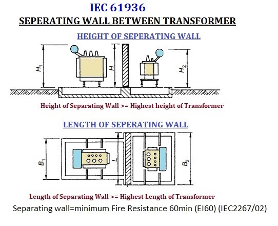
Transformer type Liquid volume Clearance to other transformers or non-combustible building surface Clearance to combustible building surface Oil insulated transformers (O) 1000 Liter to 2000 Liter 3 Meter 7.6 Meter 2000 Litre to 20000 Litre 5 Meter 10 Meter 20000 Litre to 45000 Litre 10 Meter 20 Meter More than 45000 Liter 15.2 Meter 30.5 Meter Less flammable liquid insulated transformers (K) without enhanced protection 1000 Liter to 3800 Liter 1.5 Meter 7.6 Meter More than 3800 Liter 4.6 Meter 15.2 Meter Less flammable liquid insulated transformers (K) with enhanced protection Clearance to building surface or adjacent transformers Horizonal =0.9 Meter Vertical=1.5 Meter Dry-type transformers (A) Fire behavior’s class Clearance G to building surface or adjacent transformers Horizonal vertical F0 1.5 Meter 3 Meter F1/F2 NILL NILL Note: If automatically activated fire extinguishing equipment is installed, the clearance can be reduced Note: If it is not possible to allow for adequate clearance as indicated in table 3, fire-resistant separating walls with the following dimensions shall be provided: Between transformers (see figure) separating walls. For example EI 60 in accordance (i) Height: top of the expansion chamber (if any), otherwise the top of the transformer tank; (ii) Length: width or length of the sump (in the case of a dry-type transformer, the width or length of the transformer, depending upon the direction of the transformer); Note: Where transformers with a liquid volume below 1000 Litre are installed near combustible walls, special fire precautions may be necessary depending on the nature and the use of the building

1111

IEC 61936-1-TABLE 4 – MINIMUM REQUIREMENTS FOR THE INSTALLATION OF INDOOR TRANSFORMERS

Transformer type Liquid volume Safeguard Oil insulated transformers (O) <=1000 Liter EI 60 respectively REI 60 More than 1000 Liter EI 90 respectively REI 90 or EI 60 respectively REI 60 and automatic sprinkler protection Less flammable liquid insulated transformers (K) without enhanced protection EI 60 respectively REI 60 or automatic sprinkler protection Less flammable liquid insulated transformers (K) with enhanced protection <= 10 MVA and Um <= 38 kV EI 60 respectively REI 60 or separation distances 1.5 Meter horizontally and 3.0 Meter vertically Dry-type transformers (A) Fire behavior’s class F0 EI 60 respectively REI 60 or separation distances 0.9 Meter horizontally and 1.5 Meter vertically F1/F2 Non-combustible walls Note: Between transformers and buildings separating walls shall be provided. For example EI 60; if additional fire separating wall is not provided, fire rating of the building wall should be increased, for example REI 90

IS 3034: 1993

SIZE OF TRANSFORMER FIRE PROTECTION <=10 MVA or Oil filled Transformers with oil capacity of <=2 000 Liters No fixed fire protection equipment (such as high velocity spray) is required >10 MVA or Oil filled Transformers with oil capacity of >2 000 Litres High velocity water spray system, shall be provided. This system shall be separately mounted and designed to take into account the possibility of a transformer explosion. The water spray deluge valve house shall be located outside the transformer fire zones and protected from radiant heat and other fire effects. The actuation of this system shall be automatic but manual operating valves shall also be provided The positioning of the nozzles should be such to protect all surfaces of the transformer and to give discharge rate for the system not less than 10 Ipm/m of the area to be protected. The automatic high velocity water spray shall be of pre-active with quartzoid bulbs. Distance between two transformers is less than 15 Meter apart or where the oil capacity > 2000 Liters Fire barriers walls shall be provided between transformers. Transformers having an aggregate oil capacity exceeding 2000 liters but an individual oil capacity of fewer than 5000 liters Separating walls shall not be necessary. If the distance between transformers and other apparatus is more than 6 Meter If the transformers are protected by an approved high-velocity water spray system

IS 3034: 1993-TABLE 1 CLEARANCE FROM WATER SPRAY EQUIPMENT TO LIVE UN ATTENDED ELECTRICAL COMPONENTS

Nominal Line Voltage Design BIL Minimum Clearance up to 15KV 110KV 178MM 23KV 150KV 254MM 34.5KV 200KV 330MM 46KV 250KV 432MM 69KV 350KV 635MM 115KV 550KV 940MM 138KV 650KV 1118MM 161KV 750KV 1321MM 196 TO 230KV 900-1050KV 1600-1930MM 287 TO 380KV 1175-1550KV 2210-3048MM 500KV 1675-1880KV 3327-3607MM 500 TO 700KV 1925 -2300KV 3886-4674MM

SECTION 64 IN THE INDIAN ELECTRICITY RULES, 1956

2000 liters of oil installed, whether indoor or out-doors The baffle walls of 4-hour fire rating shall be provided be…

Transformer Clearance (Indoor and Outdoor) and Fire Protection (PART-2)

TRANSFORMER CLEARANCE (INDOOR AND OUTDOOR) AND FIRE PROTECTION-PART-2

FIRE PROTECTION FOR POWER PLANTS (NFPA 850)

LOCATION

TYPE OF TRANSFORMER

DETAILS

OUTDOOR

Oil-insulated outdoor type transformer containing 1890 liters or more of oil It is strongly recommended that any is separated from nearby structures by a 2-hour–rated firewall Wherever a firewall is installed between transformers , it should extend at least 1 ft (0.31 m) above the top of the transformer shell and oil tank and at least 2 ft (0.61 m) beyond the width of the transformer and cooling radiators.

INDOOR

Dry type Transformer Dry-type transformers are strongly preferred for use inside buildings. oil-insulated transformer In case however, an oil-insulated transformer is installed indoors, then if its oil content exceeds 379 Liters, then it should be separated from nearby areas by a fire barrier of 3-hour fire resistance rating. In case an automatic fire extinguishment system is installed, then it is allowed that the fire resistance rating of the fire barrier is reduced to 1 hour.

NFPA 850 – TABLE 6.1.4.3-OUTDOOR OIL-INSULATED TRANSFORMER SEPARATION CRITERIA

Transformer Oil Capacity Minimum (Line-of-Sight) Separation Without Firewall

<1893 Liter

1.5 Meter 1893 liter to 18925 liter

7.5 Meter

18925 liter

15 Meter

4.2-SUBSTATIONS AND SWITCH ROOMS (NATIONAL BUILDING CODE 2016)

Oil Filled Transformer at Basement Level (Indoor Type)

Substations with oil-filled equipment/ apparatus Transformers and high voltage panels shall be either located in open or in a utility building. They shall not be located in any floor other than the ground floor or the first basement of a utility building. They shall not be located below first basement Slab (On Second Basement) of utility building. They shall have direct access from outside the building for operation and maintenance of the equipment. In respect of all oil type transformers located at basement, a kerb (sill) of a suitable height shall be provided at the entrance in order to prevent the flow of oil from a ruptured transformer into other parts of the basement in the event of the possibility of oil spillage from the transformer on its failure.

Oil Filled Transformer/ Sub Station (Outdoor Type)

The substation or oil-filled transformer is located shall be separated from the adjoining buildings including the main building by at least 6 Meter clear distance to allow passage of fire tender between the substation/utility building and adjoining building/main building. There shall be no interconnecting basement with the main building underneath the oil-filled transformers. Provisions for oil drainage to a point at a lower level and separated by adequate fire barrier shall be provided. If there is a floor directly below the ground floor level or first basement where the oil-filled transformers and oil-filled circuit breakers are placed, then they shall be separated by a fire barrier of appropriate fire rating as per Part 4 Fire and Life Safety of the Code and proper oil drainage system shall be provided to avoid possible leakage of oil into the lower floor. Substation equipment (exceeding oil capacity of 2 000 liter) in utility building shall have fire rated baffle walls of 240 min rating constructed between such equipment, raised to at least 600 mm above the height of the equipment (including height of oil conservators) and exceeding 300 mm on each side of the equipment All transformers where capacity exceeds 10 MVA shall be protected by high velocity water spray systems or nitrogen injection system.

Oil Filled Transformer (9000 Liter) (Indoor / Outdoor Type)

Provisions shall be made for suitable oil soak-pit, and where use of more than 9 000 liter of oil in any one oil tank, receptacle or chamber is involved, provision shall be made for the draining away or removal of any oil which may leak or escape from the tank, receptacle or chamber containing the same. Special precautions shall be taken to prevent the spread of any fire resulting from the ignition of the oil from any cause and adequate provision shall be made for extinguishing any fire which may occur.

Dry-Type Transformer Within Multi-Storied Building

Dry-type installation In case electric substation has to be located within the main multistoried building itself for unavoidable reasons, it shall be a dry-type installation with very little combustible material, such as, a dry type transformer with vacuum (or SF6) breakers as HT switchgear and ACB or MCCB as medium voltage (MV) switchgear. Such substations shall be located on the ground level or on first basement, and shall have direct access from the outside of the building for operation and maintenance of the equipment. Exceptionally, in case of functional buildings, such as air traffic control towers, data center’s and buildings of height more than 100 m having high electrical load requi…

B

Measurement of LUX Level and Uniformity at Indoor and Outdoor Lighting (Part-1)

MEASUREMENT OF LUX LEVEL AND UNIFORMITY AT INDOOR AND OUTDOOR LIGHTING (PART-1)

INTRODUCTION:

  • Working plane illuminance (Lux Level) need to be measured in the field for cross check of whether the existing installation meets a design requirement or not. * Field surveys may also be useful to identifying the causes of complaints about lighting, hence the results of field surveys may be useful for the designer, installers and end users. * There are various methods are developed for field measurement of Interior Lighting and External Lighting. * The Measurement Methods recommended by the various national lighting bodies are generally similar or slightly derivatives to each other. The most common method / Standard is BEE, CIBSE, IES and DIN code * The most of methods require to measurement of illuminance at points on a grid at working-plane height or at Floor, but the grid size and position of the measuring points may be differed from various standard to standard. * The IES method and its derivatives use the position of the grid according to the luminaire locations. * The CIBSE and DIN methods use a position of grid according to the room size. * The techniques of analysis of the field measurement results also differ

BASIC REQUIREMENTS FOR EXTERIOR & INTERIOR LIGHT LEVEL MEASUREMENT

  • The following Points should be considered for accurate measurement of interior and exterior lighting Lux level. * Where possible, use the same calibrated illuminance measurement meter (LUX Meter) If the same meter is not available, use the same make and model of calibrated meter to minimize error. * When taking measurements, verify that any objects/materials are not blocking any light to the meter head. The use of a remote meter head cabled to the meter body is recommended to prevent the operator from blocking the meter’s “view” of the lighting system being measured. * In Outdoor Lighting it is essential to measure of illuminance should be done in night (proper dark). * For indoor lighting, measurements with lights ON and Lights OFF technique can be followed and the daylight variation is not too much and the survey time is not too long. * In an installation of fluorescent discharge lamps, the lamps must be switched on at least 30 minutes before the measurement to allow for the lamps to be completely warmed up. * In many situations, the measuring plane may not be specified or even non-existent. Hence it is necessary to define measurement height, typically 0.8 to 1 meter from the ground or floor level. * The lux measurement procedure simply requires positioning a meter’s sensor on the surface or location where you wish to measure the incident light. * The sensor should face the light source at a right angle. If the sensor is not perpendicular to the light, the measurement will be incorrect, though some lux meters have a cosine correction to account for the angle. * Meters that require a colour correction factor may have a means of inputting the CCF to adjust the result for LEDs or fluorescent lights; otherwise, you will have to manually multiply the measured lux by the CCF.

 INDOOR ILLUMINATION (LUX LEVEL) MEASUREMENT.

 (1) AS PER ROOM INDEX METHOD (AS PER BEE CODE / CIBSE CODE):

  • This methos is more suitable where measuring Plan / Points for an interior is more rectangular than square. First, we need to be found Room Index. * Based on the room index, the minimum number of illuminance measurement points is decided by Room Index Number * Room Index (RI) = (L x W) / H x (L+ W) * Where L = Length of Room * W = Width of Room * H= Height of the luminaires above the plane of measurement 

Table 4-2: Number of points for measuring illuminance

Room index

Minimum number of measurement points

For ± 5% accuracy

For ± 10% accuracy

RI < 1

8

4

1 < RI < 2

18

9

2 < RI < 3

32

16

RI > 3

50

25

 Sample calculation

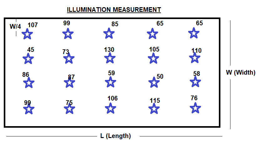
  • Measure Illumination Level of an office room have length, L = 7.5 m and width W = 5 m, * Solution: * Suppose Height of Illumination from Floor is 2 Meter * Room Index RI = (L x W) / H x (L+ W) * Room Index RI = (7.5 x 5) / 2 x (7.5+ 5) * Room Index RI = 1.5 * From Table 4.2 minimum Illumination Measure Points should be 18 No’s * The illuminance measurements Points with Measured Value in Lux are marked on the grid.

1

Measurement Reading Details

107 Lux

99 Lux

85 Lux

65 Lux

65 Lux

45 Lux

73 Lux

130 Lux

105 Lux

110 Lux

86 Lux

87 Lux

59 Lux

50 Lux

58 Lux

99 Lux

75 Lux

106 Lux

115 Lux

76 Lux

Min

45 Lux

Max

130 Lux

Average

85 Lux

U1=MIN/AVG

0.5 Lux

U2=MIN/MAX

0.3 Lux

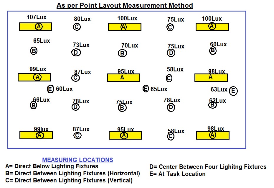
 (2) AS PER POINT LAYOUT METHOD

  • For office and other task areas, identify a set of measurements points on desktops and other work surfaces that best represents lighting conditions in the space. * It may not be possible to develop a uniform spacing grid, but points should be chosen that represent the various lighting c…