Site logo
Electrical Engineering Academy
C

Type & Selection of Fuse

MEASUREMENT OF LUX LEVEL AND UNIFORMITY AT INDOOR AND OUTDOOR LIGHTING (PART-2)

(3) AS PER DEUTSCH NORM DIN 5035

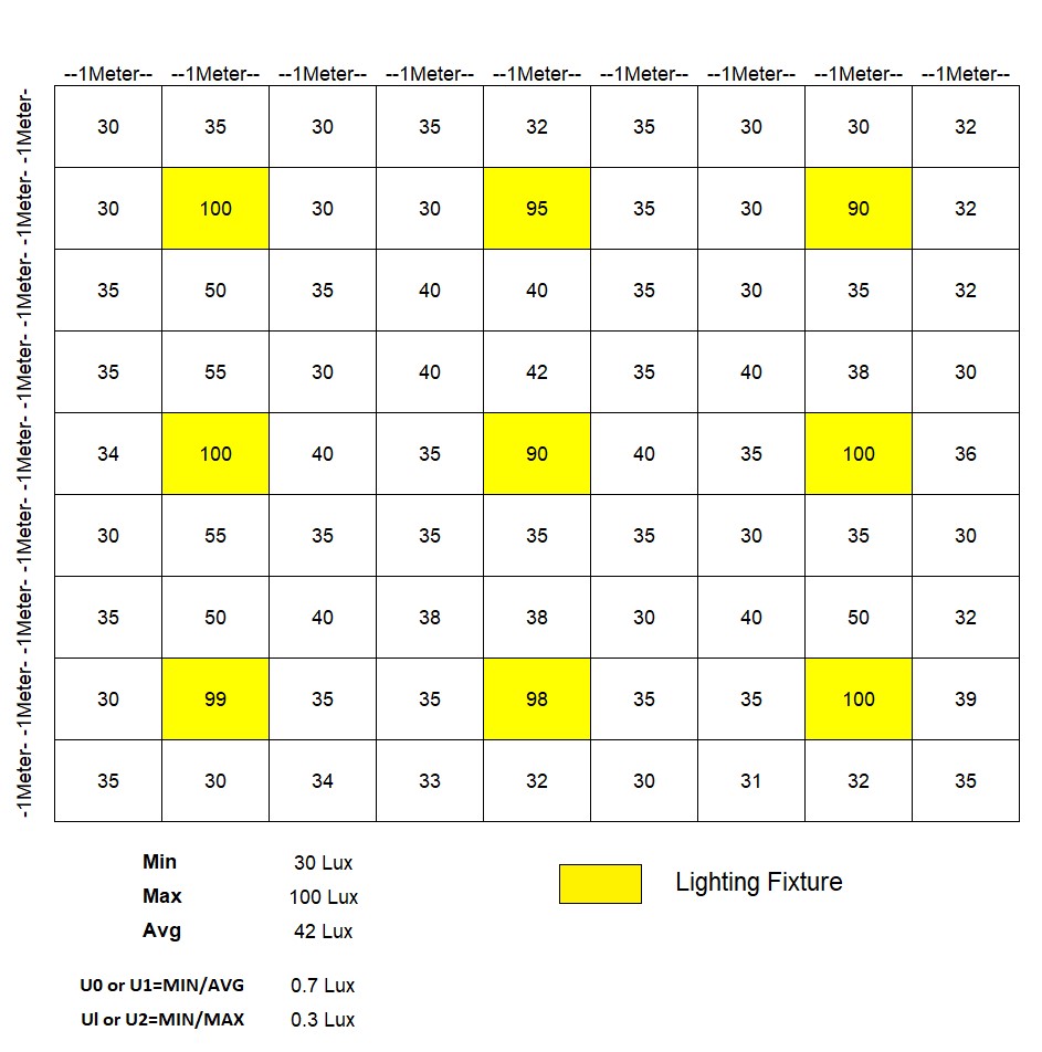
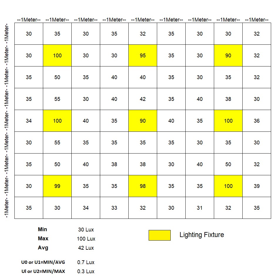
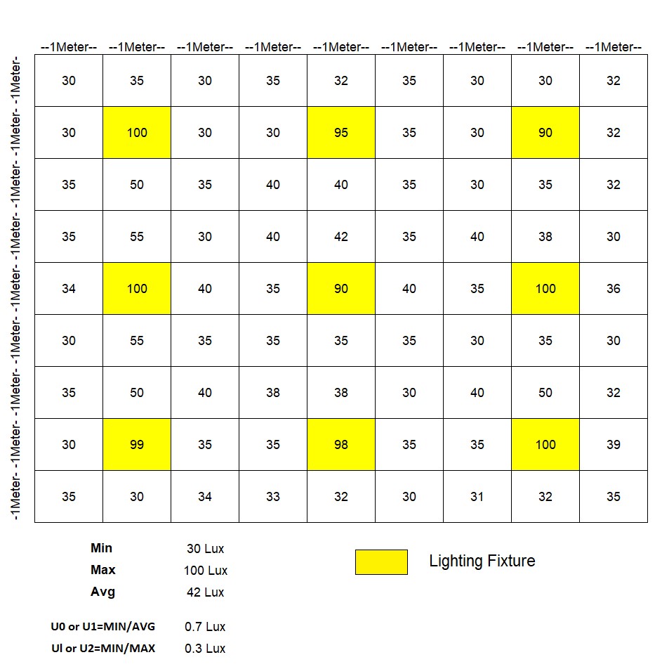
  • In this Method the working plane divide into a number of sections which are at least rectangular, of ratio of length to side not less than 1: 2 but which are preferably of square shape. * A square grid of minimum size 1 meter is established within each section with a measurement point at the centre of each square. * The grid module defining the measurement points is selected so as not to coincide with the luminaire grid in either principal direction. * In exceptionally large interiors the grid size may be up to 5 meters. there is not any mention of accuracy limits of the method, but this is not surprising given the flexibility which the user of the method is allowed in choice of grid size. * The DIN system is the only one of the three methods studied to give any advice concerning illuminance measurements in obstructed interiors. Areas of the working plane located between large obstructions are treated for measurement purposes as separate spaces.

1

OUTDOOR ILLUMINATION (LUX LEVEL) MEASUREMENT

 (1) NINE POINT METHOD FOR DETERMINING LUX LEVELS IN STREET LIGHTING

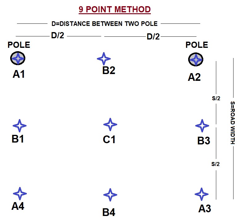
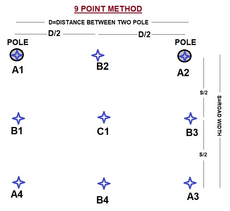
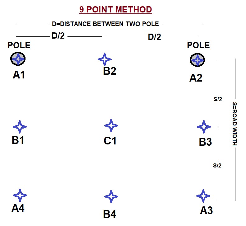
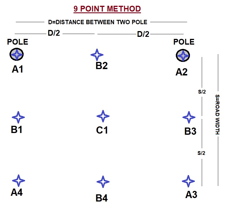
  • The Lux Level of Street Light is measured by 9-point method. * We need to make two equal quadrants between two light poles and between Pole and Rode edge. * Two Measuring Points below Light Pole (A1,A2) and Two opposite side of Pole at Road Edge (A3,A4). * Two Point between Pole and Road edge (B1,B3). * One Point Between Pole (B2) and on One Point between opposite side of Pole at road edge (B4) * One Point is at centre (C1). * Average Lux = (A1+A2+A3+A4)/16 + (B1+B2+B3+B4)/8 +C1/4

2

  • Solution

26 Lux 27 Lux 13 Lux 12 Lux 15 Lux 14 Lux 26 Lux 32 Lux 22 Lux

  • Average Lux = (A1+A2+A3+A4)/16 + (B1+B2+B3+B4)/8 +C1/4 * Average Lux = (26+26+13+22)/16 + (12+27+14+32)/8 +15/4 * Average Lux =20Lux 

MIN 12 Lux MAX 32 Lux AVG 20 Lux U1=MIN/AVG 0.58 U2=MIN/MAX 0.38

 (2) AS PER GRID POINT SET UP MEASUREMENT

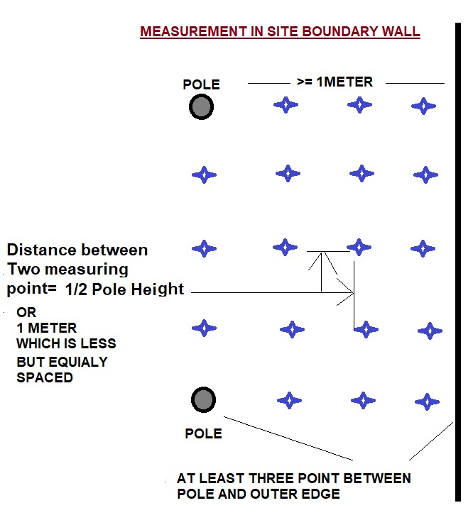
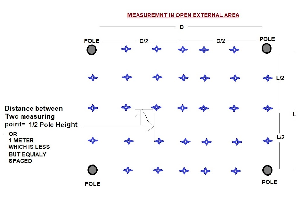
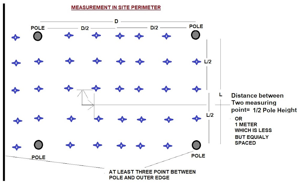
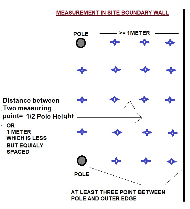
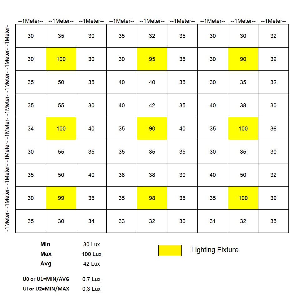
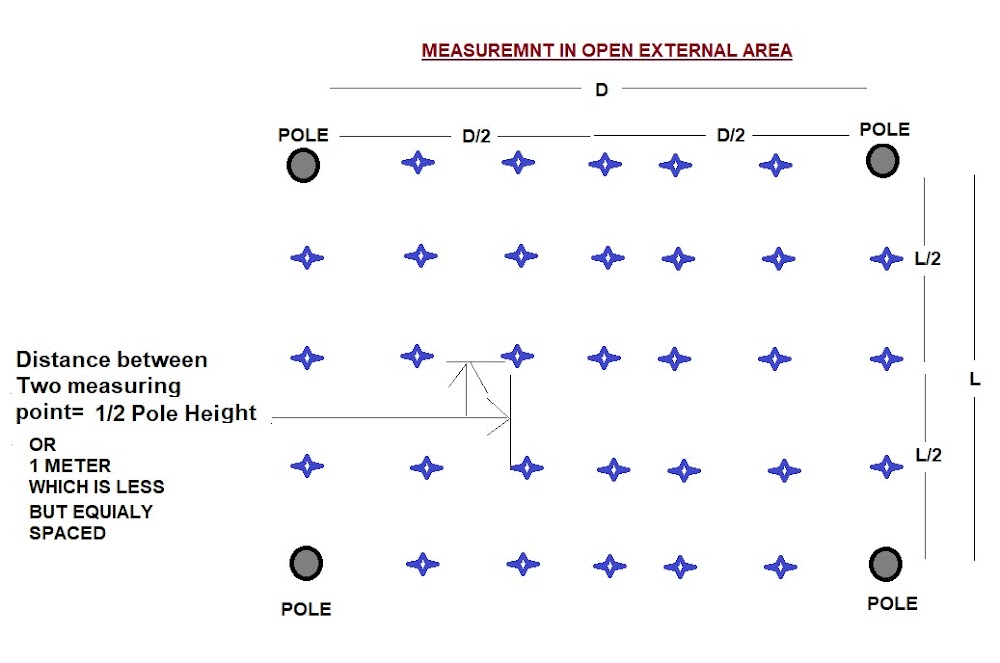
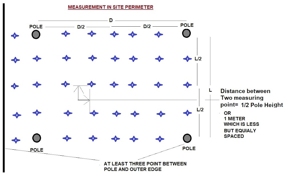
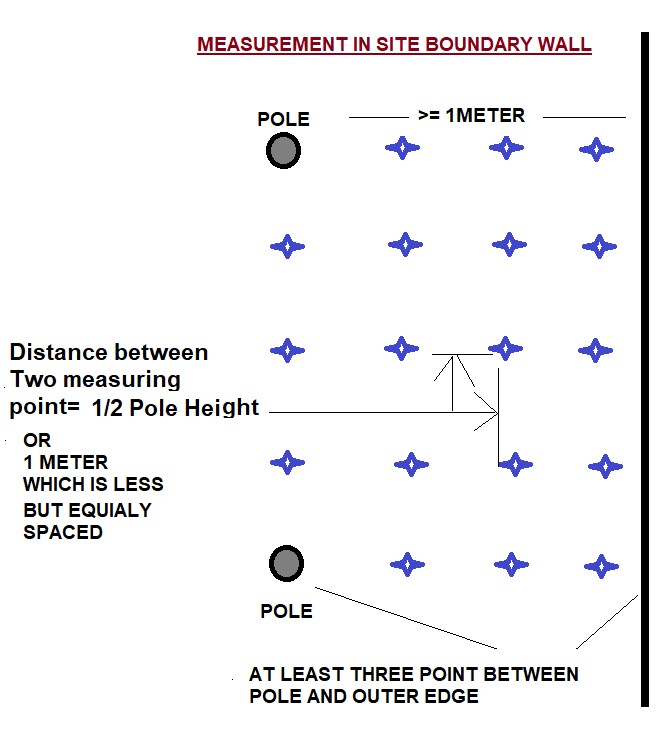
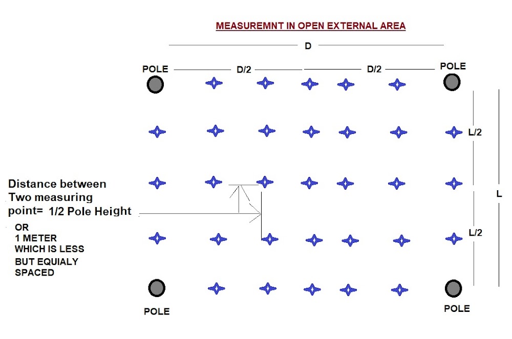
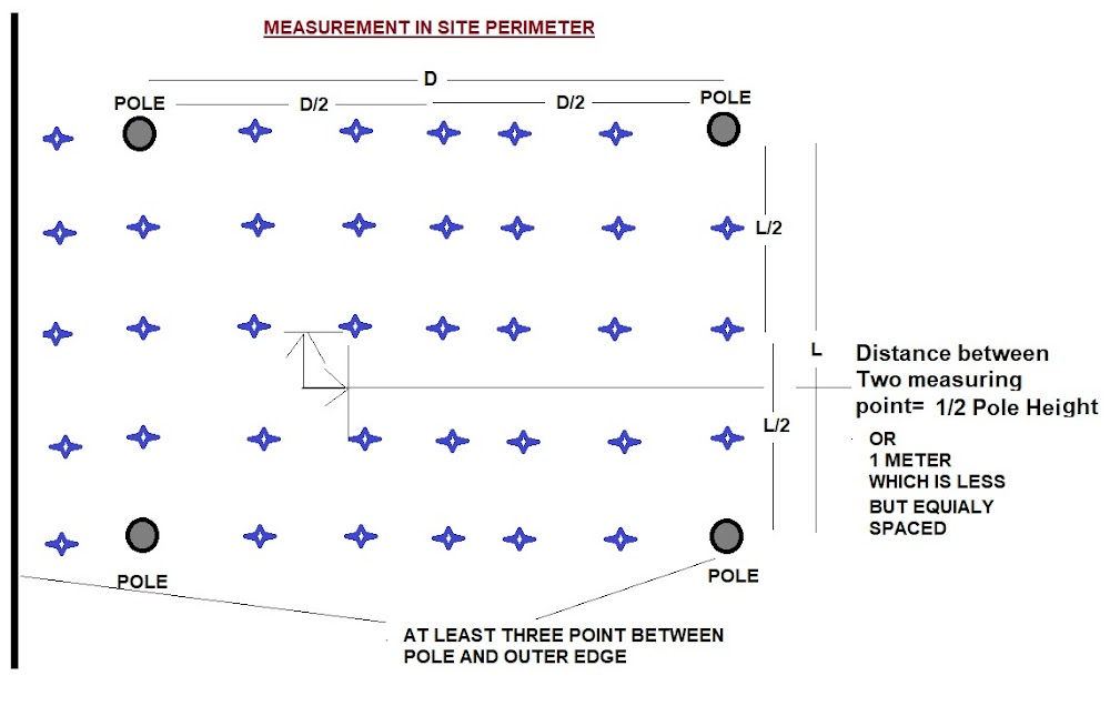
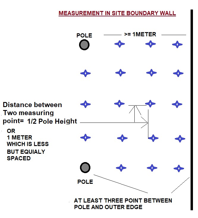
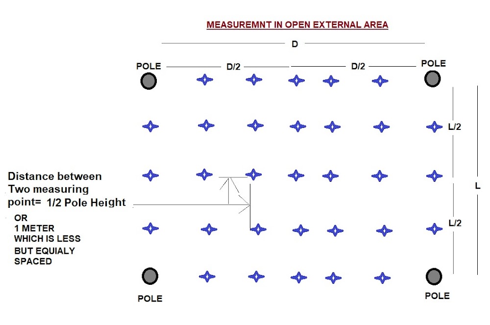
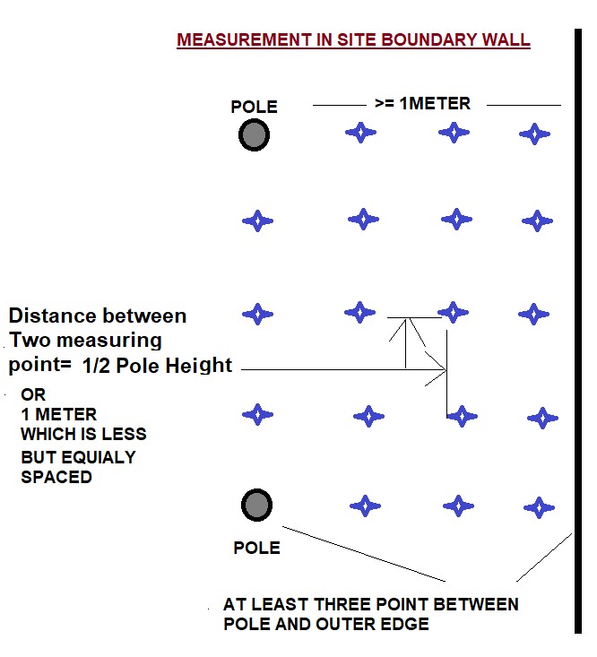
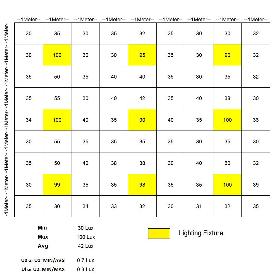
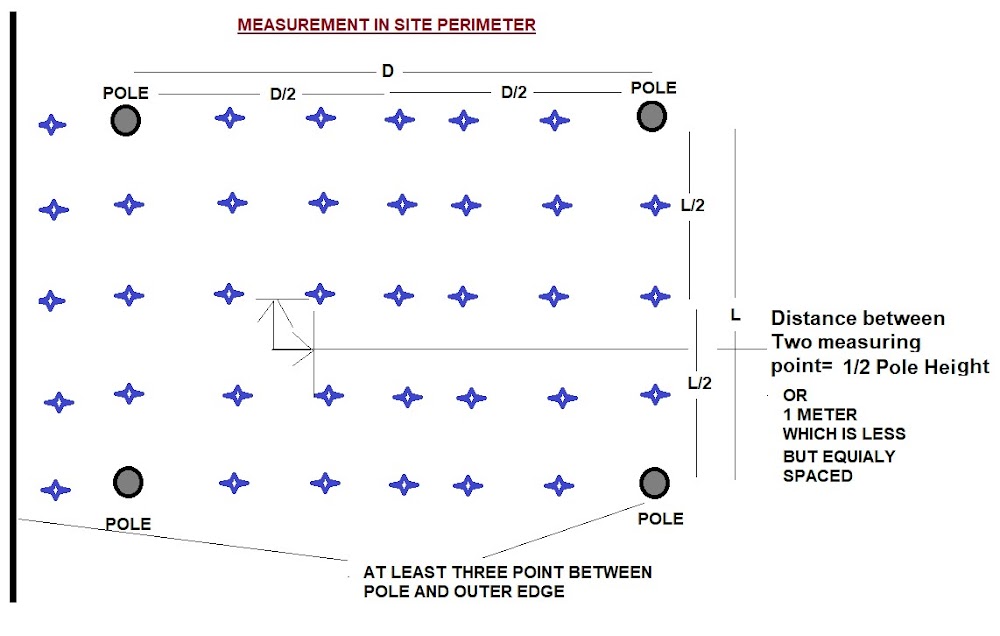
  • Identify a horizontal grid of measurement points on the Illumination Measurement site surface. Locate measurement points on gridlines covering the test measurement area. * Ensure that the spacing between measurement points is uniform in both directions and is less than one-half the pole height or less than 4.5 Meter, whichever is smaller. * For installations with lights spaced less than 4.5 Meter apart, locate measurement points no farther apart that one-half the pole height, with at least three points between poles in both directions. * Record the location of all measurement grids and point layouts with dimensions from surrounding poles or other structures. Provide this information, including a sketch or rendering of the grid layouts. * For open areas such as main parking, make the measurement grid large enough to cover at least four poles of this Area layout and at least two Pole are covered. * For site perimeter open areas or areas adjacent to a building edge establish the test area measurement grid in a typical perimeter or building edge area. The depth of the test area should extend from the paved site boundary or building edge inward to the nearest line of light poles that are at least 4.5 Meter from the boundary or building edge. * The width of the test area must cover at least two of the poles in the line that is at least 4.5 Meter from the boundary or building edge.

(A) IN OPEN AREA

3

(B) IN THE AREA OF SITE PERIMETER

4

(C) NEAR SITE BOUNDARY AREA:

5
C

Specification for Re wirable Cut Out Fuse Unit

MEASUREMENT OF LUX LEVEL AND UNIFORMITY AT INDOOR AND OUTDOOR LIGHTING (PART-2)

(3) AS PER DEUTSCH NORM DIN 5035

  • In this Method the working plane divide into a number of sections which are at least rectangular, of ratio of length to side not less than 1: 2 but which are preferably of square shape. * A square grid of minimum size 1 meter is established within each section with a measurement point at the centre of each square. * The grid module defining the measurement points is selected so as not to coincide with the luminaire grid in either principal direction. * In exceptionally large interiors the grid size may be up to 5 meters. there is not any mention of accuracy limits of the method, but this is not surprising given the flexibility which the user of the method is allowed in choice of grid size. * The DIN system is the only one of the three methods studied to give any advice concerning illuminance measurements in obstructed interiors. Areas of the working plane located between large obstructions are treated for measurement purposes as separate spaces.

1

OUTDOOR ILLUMINATION (LUX LEVEL) MEASUREMENT

 (1) NINE POINT METHOD FOR DETERMINING LUX LEVELS IN STREET LIGHTING

  • The Lux Level of Street Light is measured by 9-point method. * We need to make two equal quadrants between two light poles and between Pole and Rode edge. * Two Measuring Points below Light Pole (A1,A2) and Two opposite side of Pole at Road Edge (A3,A4). * Two Point between Pole and Road edge (B1,B3). * One Point Between Pole (B2) and on One Point between opposite side of Pole at road edge (B4) * One Point is at centre (C1). * Average Lux = (A1+A2+A3+A4)/16 + (B1+B2+B3+B4)/8 +C1/4

2

  • Solution

26 Lux 27 Lux 13 Lux 12 Lux 15 Lux 14 Lux 26 Lux 32 Lux 22 Lux

  • Average Lux = (A1+A2+A3+A4)/16 + (B1+B2+B3+B4)/8 +C1/4 * Average Lux = (26+26+13+22)/16 + (12+27+14+32)/8 +15/4 * Average Lux =20Lux 

MIN 12 Lux MAX 32 Lux AVG 20 Lux U1=MIN/AVG 0.58 U2=MIN/MAX 0.38

 (2) AS PER GRID POINT SET UP MEASUREMENT

  • Identify a horizontal grid of measurement points on the Illumination Measurement site surface. Locate measurement points on gridlines covering the test measurement area. * Ensure that the spacing between measurement points is uniform in both directions and is less than one-half the pole height or less than 4.5 Meter, whichever is smaller. * For installations with lights spaced less than 4.5 Meter apart, locate measurement points no farther apart that one-half the pole height, with at least three points between poles in both directions. * Record the location of all measurement grids and point layouts with dimensions from surrounding poles or other structures. Provide this information, including a sketch or rendering of the grid layouts. * For open areas such as main parking, make the measurement grid large enough to cover at least four poles of this Area layout and at least two Pole are covered. * For site perimeter open areas or areas adjacent to a building edge establish the test area measurement grid in a typical perimeter or building edge area. The depth of the test area should extend from the paved site boundary or building edge inward to the nearest line of light poles that are at least 4.5 Meter from the boundary or building edge. * The width of the test area must cover at least two of the poles in the line that is at least 4.5 Meter from the boundary or building edge.

(A) IN OPEN AREA

3

(B) IN THE AREA OF SITE PERIMETER

4

(C) NEAR SITE BOUNDARY AREA:

5
C

Over Current Relay(Type-Application-Connection)

MEASUREMENT OF LUX LEVEL AND UNIFORMITY AT INDOOR AND OUTDOOR LIGHTING (PART-2)

(3) AS PER DEUTSCH NORM DIN 5035

  • In this Method the working plane divide into a number of sections which are at least rectangular, of ratio of length to side not less than 1: 2 but which are preferably of square shape. * A square grid of minimum size 1 meter is established within each section with a measurement point at the centre of each square. * The grid module defining the measurement points is selected so as not to coincide with the luminaire grid in either principal direction. * In exceptionally large interiors the grid size may be up to 5 meters. there is not any mention of accuracy limits of the method, but this is not surprising given the flexibility which the user of the method is allowed in choice of grid size. * The DIN system is the only one of the three methods studied to give any advice concerning illuminance measurements in obstructed interiors. Areas of the working plane located between large obstructions are treated for measurement purposes as separate spaces.

1

OUTDOOR ILLUMINATION (LUX LEVEL) MEASUREMENT

 (1) NINE POINT METHOD FOR DETERMINING LUX LEVELS IN STREET LIGHTING

  • The Lux Level of Street Light is measured by 9-point method. * We need to make two equal quadrants between two light poles and between Pole and Rode edge. * Two Measuring Points below Light Pole (A1,A2) and Two opposite side of Pole at Road Edge (A3,A4). * Two Point between Pole and Road edge (B1,B3). * One Point Between Pole (B2) and on One Point between opposite side of Pole at road edge (B4) * One Point is at centre (C1). * Average Lux = (A1+A2+A3+A4)/16 + (B1+B2+B3+B4)/8 +C1/4

2

  • Solution

26 Lux 27 Lux 13 Lux 12 Lux 15 Lux 14 Lux 26 Lux 32 Lux 22 Lux

  • Average Lux = (A1+A2+A3+A4)/16 + (B1+B2+B3+B4)/8 +C1/4 * Average Lux = (26+26+13+22)/16 + (12+27+14+32)/8 +15/4 * Average Lux =20Lux 

MIN 12 Lux MAX 32 Lux AVG 20 Lux U1=MIN/AVG 0.58 U2=MIN/MAX 0.38

 (2) AS PER GRID POINT SET UP MEASUREMENT

  • Identify a horizontal grid of measurement points on the Illumination Measurement site surface. Locate measurement points on gridlines covering the test measurement area. * Ensure that the spacing between measurement points is uniform in both directions and is less than one-half the pole height or less than 4.5 Meter, whichever is smaller. * For installations with lights spaced less than 4.5 Meter apart, locate measurement points no farther apart that one-half the pole height, with at least three points between poles in both directions. * Record the location of all measurement grids and point layouts with dimensions from surrounding poles or other structures. Provide this information, including a sketch or rendering of the grid layouts. * For open areas such as main parking, make the measurement grid large enough to cover at least four poles of this Area layout and at least two Pole are covered. * For site perimeter open areas or areas adjacent to a building edge establish the test area measurement grid in a typical perimeter or building edge area. The depth of the test area should extend from the paved site boundary or building edge inward to the nearest line of light poles that are at least 4.5 Meter from the boundary or building edge. * The width of the test area must cover at least two of the poles in the line that is at least 4.5 Meter from the boundary or building edge.

(A) IN OPEN AREA

3

(B) IN THE AREA OF SITE PERIMETER

4

(C) NEAR SITE BOUNDARY AREA:

5

C

Types and Revolution of Electrical Relays

MEASUREMENT OF LUX LEVEL AND UNIFORMITY AT INDOOR AND OUTDOOR LIGHTING (PART-2)

(3) AS PER DEUTSCH NORM DIN 5035

  • In this Method the working plane divide into a number of sections which are at least rectangular, of ratio of length to side not less than 1: 2 but which are preferably of square shape. * A square grid of minimum size 1 meter is established within each section with a measurement point at the centre of each square. * The grid module defining the measurement points is selected so as not to coincide with the luminaire grid in either principal direction. * In exceptionally large interiors the grid size may be up to 5 meters. there is not any mention of accuracy limits of the method, but this is not surprising given the flexibility which the user of the method is allowed in choice of grid size. * The DIN system is the only one of the three methods studied to give any advice concerning illuminance measurements in obstructed interiors. Areas of the working plane located between large obstructions are treated for measurement purposes as separate spaces.

1

OUTDOOR ILLUMINATION (LUX LEVEL) MEASUREMENT

 (1) NINE POINT METHOD FOR DETERMINING LUX LEVELS IN STREET LIGHTING

  • The Lux Level of Street Light is measured by 9-point method. * We need to make two equal quadrants between two light poles and between Pole and Rode edge. * Two Measuring Points below Light Pole (A1,A2) and Two opposite side of Pole at Road Edge (A3,A4). * Two Point between Pole and Road edge (B1,B3). * One Point Between Pole (B2) and on One Point between opposite side of Pole at road edge (B4) * One Point is at centre (C1). * Average Lux = (A1+A2+A3+A4)/16 + (B1+B2+B3+B4)/8 +C1/4

2

  • Solution

26 Lux 27 Lux 13 Lux 12 Lux 15 Lux 14 Lux 26 Lux 32 Lux 22 Lux

  • Average Lux = (A1+A2+A3+A4)/16 + (B1+B2+B3+B4)/8 +C1/4 * Average Lux = (26+26+13+22)/16 + (12+27+14+32)/8 +15/4 * Average Lux =20Lux 

MIN 12 Lux MAX 32 Lux AVG 20 Lux U1=MIN/AVG 0.58 U2=MIN/MAX 0.38

 (2) AS PER GRID POINT SET UP MEASUREMENT

  • Identify a horizontal grid of measurement points on the Illumination Measurement site surface. Locate measurement points on gridlines covering the test measurement area. * Ensure that the spacing between measurement points is uniform in both directions and is less than one-half the pole height or less than 4.5 Meter, whichever is smaller. * For installations with lights spaced less than 4.5 Meter apart, locate measurement points no farther apart that one-half the pole height, with at least three points between poles in both directions. * Record the location of all measurement grids and point layouts with dimensions from surrounding poles or other structures. Provide this information, including a sketch or rendering of the grid layouts. * For open areas such as main parking, make the measurement grid large enough to cover at least four poles of this Area layout and at least two Pole are covered. * For site perimeter open areas or areas adjacent to a building edge establish the test area measurement grid in a typical perimeter or building edge area. The depth of the test area should extend from the paved site boundary or building edge inward to the nearest line of light poles that are at least 4.5 Meter from the boundary or building edge. * The width of the test area must cover at least two of the poles in the line that is at least 4.5 Meter from the boundary or building edge.

(A) IN OPEN AREA

3

(B) IN THE AREA OF SITE PERIMETER

4

(C) NEAR SITE BOUNDARY AREA:

5

C

Working Principle of ELCB and RCB

MEASUREMENT OF LUX LEVEL AND UNIFORMITY AT INDOOR AND OUTDOOR LIGHTING (PART-2)

(3) AS PER DEUTSCH NORM DIN 5035

  • In this Method the working plane divide into a number of sections which are at least rectangular, of ratio of length to side not less than 1: 2 but which are preferably of square shape. * A square grid of minimum size 1 meter is established within each section with a measurement point at the centre of each square. * The grid module defining the measurement points is selected so as not to coincide with the luminaire grid in either principal direction. * In exceptionally large interiors the grid size may be up to 5 meters. there is not any mention of accuracy limits of the method, but this is not surprising given the flexibility which the user of the method is allowed in choice of grid size. * The DIN system is the only one of the three methods studied to give any advice concerning illuminance measurements in obstructed interiors. Areas of the working plane located between large obstructions are treated for measurement purposes as separate spaces.

1

OUTDOOR ILLUMINATION (LUX LEVEL) MEASUREMENT

 (1) NINE POINT METHOD FOR DETERMINING LUX LEVELS IN STREET LIGHTING

  • The Lux Level of Street Light is measured by 9-point method. * We need to make two equal quadrants between two light poles and between Pole and Rode edge. * Two Measuring Points below Light Pole (A1,A2) and Two opposite side of Pole at Road Edge (A3,A4). * Two Point between Pole and Road edge (B1,B3). * One Point Between Pole (B2) and on One Point between opposite side of Pole at road edge (B4) * One Point is at centre (C1). * Average Lux = (A1+A2+A3+A4)/16 + (B1+B2+B3+B4)/8 +C1/4

2

  • Solution

26 Lux 27 Lux 13 Lux 12 Lux 15 Lux 14 Lux 26 Lux 32 Lux 22 Lux

  • Average Lux = (A1+A2+A3+A4)/16 + (B1+B2+B3+B4)/8 +C1/4 * Average Lux = (26+26+13+22)/16 + (12+27+14+32)/8 +15/4 * Average Lux =20Lux 

MIN 12 Lux MAX 32 Lux AVG 20 Lux U1=MIN/AVG 0.58 U2=MIN/MAX 0.38

 (2) AS PER GRID POINT SET UP MEASUREMENT

  • Identify a horizontal grid of measurement points on the Illumination Measurement site surface. Locate measurement points on gridlines covering the test measurement area. * Ensure that the spacing between measurement points is uniform in both directions and is less than one-half the pole height or less than 4.5 Meter, whichever is smaller. * For installations with lights spaced less than 4.5 Meter apart, locate measurement points no farther apart that one-half the pole height, with at least three points between poles in both directions. * Record the location of all measurement grids and point layouts with dimensions from surrounding poles or other structures. Provide this information, including a sketch or rendering of the grid layouts. * For open areas such as main parking, make the measurement grid large enough to cover at least four poles of this Area layout and at least two Pole are covered. * For site perimeter open areas or areas adjacent to a building edge establish the test area measurement grid in a typical perimeter or building edge area. The depth of the test area should extend from the paved site boundary or building edge inward to the nearest line of light poles that are at least 4.5 Meter from the boundary or building edge. * The width of the test area must cover at least two of the poles in the line that is at least 4.5 Meter from the boundary or building edge.

(A) IN OPEN AREA

3

(B) IN THE AREA OF SITE PERIMETER

4

(C) NEAR SITE BOUNDARY AREA:

5
C

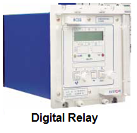
Types and Revolution of Electrical Relays

TYPES AND REVOLUTION OF ELECTRICAL RELAYS

INTRODUCTION:

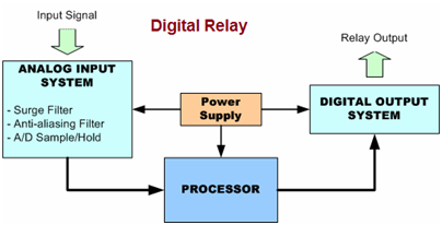
  • Protective relays work in concert with sensing and control devices to accomplish their function. Under normal power system operation, a protective relay remains idle and serves no active function. But when fault or undesirable condition arrives Relay must be operated and function correctly. * A Power System consists of various electrical components like Generator, transformers, transmission lines, isolators, circuit breakers, bus bars, cables, relays, instrument transformers, distribution feeders, and various types of loads. Faults may occur in any part of power system as a short circuit & earth fault. Fault may be Single Line to Ground, Double Line to Ground, Line to Line, three phase short circuit etc. This results in flow of heavy fault current through the system. Fault level also depends on the fault impedance which depends on the location of fault referred from the source side. To calculate fault level at various points in the power system, fault analysis is necessary. * The protection system operates and isolates the faulty section. The operation of the protection system should be fast and selective i.e. it should isolate only the faulty section in the shortest possible time causing minimum disturbance to the system. Also, if main protection fails to operate, there should be a backup protection for which proper relay co-ordination is necessary. Failure of a protective relay can result in devastating equipment damage and prolonged downtime.

 WORKING OF PROTECTIVE SCHEME:

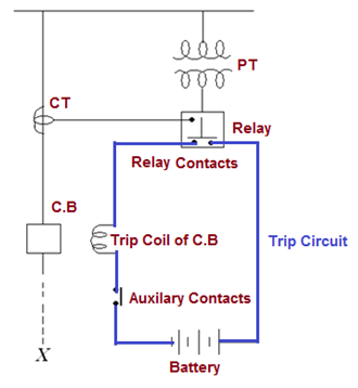
  • Protective relaying senses the abnormal condition in a part of power system and gives an alarm or isolates that part from healthy system. Protective relaying is a team work of CT, PT, protective relays, time delay relays, trip circuits, circuit breakers etc. * Protective relaying plays an important role in minimizing the faults and also in minimizing the damage in the event of faults.

 1

  • Figure shows basic connections of circuit breaker control for the opening operation. The protected circuit X is shown by dashed line. When a fault occurs in the protected circuit the relay connected to CT and PT actuates and closes its contacts. * Current flows from battery in the trip circuit. As the trip coil of circuit breaker is energized, the circuit breaker operating mechanism is actuated and it operates for the opening operation. Thus the fault is sensed and the trip circuit is actuated by the relay and the faulty part is isolated.

WHAT IS RELAY:

  • A relay is automatic device which senses an abnormal condition of electrical circuit and closes its contacts. These contacts in turns close and complete the circuit breaker trip coil circuit hence make the circuit breaker tripped for disconnecting the faulty portion of the electrical circuit from rest of the healthy circuit.

FUNCTIONS OF PROTECTIVE RELAY:

  • To sound an alarm or to close the trip circuit of a circuit breaker so as to disconnect Faulty Section. * To disconnect the abnormally operating part so as to prevent subsequent faults. For e.g. Overload protection of a machine not only protects the machine but also prevents Insulation failure. * To isolate or disconnect faulted circuits or equipment quickly from the remainder of the system so the system can continue to function and to minimize the damage to the faulty part. For example – If machine is disconnected immediately after a winding fault, only a few coils may need replacement. But if the fault is sustained, the entire winding may get damaged and machine may be beyond repairs. * To localize the effect of fault by disconnecting the faulty part from healthy part, causing least disturbance to the healthy system. * To disconnect the faulty part quickly so as to improve system stability, service continuity and system performance. Transient stability can be improved by means of improved protective relaying. * To minimize hazards to personnel

DESIRABLE QUALITIES OF PROTECTIVE RELAYING:

  1. Selectivity, 2. Discrimination 3. Stability 4. Sensitivity, 5. Power consumption 6. System Security 7. Reliability 8. Adequateness 9. Speed & Time

TERMINOLOGY OF PROTECTIVE RELAY:

  • Pickup level of actuating signal: The value of actuating quantity (voltage or current) which is on threshold above which the relay initiates to be operated. If the value of actuating quantity is increased, the electromagnetic effect of the relay coil is increased and above a certain level of actuating quantity the moving mechanism of the relay just starts to move. * Reset level: The value of current or voltage below which a relay opens its contacts and comes in original position. * Operating Time of Relay: Just after exceeding pickup level of actuating quantity the moving mechanism (for example rotating disc…
C

FORM of Separation for Panel- PART-1

FORMS OF SEPARATION FOR PANEL (PART-1)

INTRODUCTION:

  • Forms of segregation have great importance in electrical Panel designs. * Form of segregation is the rule for provide separation from a one energizes function part to other energize function pant and access to a part of the assembly while other parts may remain energized. This can be achieved by using metallic or non-metallic physical barriers or insulation. * The form of segregation provides protection against four objectives.
  1. Protection against direct contact with live dangerous parts of adjacent functional units. 2. Protection against the entry of solid objects from one unit of an assembly to an adjacent unit. 3. Limitation of the effects of the spread of electric arcs. 4. Facilitation of panel maintenance operations.

TYPE OF SEPARATION:

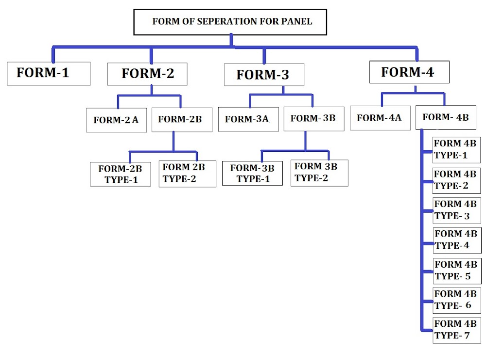
  • As specified by AS / NZS / IEC 61439, There are four main categories outlined by the standard for internally separating the switchgear units and busbars of a Panel are
  1. Form 1 (No segregation between busbar, terminals and Switchgear units) 2. Form 2 (Separation between switchgear units and the busbar) 3. Form 3 (Separation are between switchgear units and the busbar and Separation between Switchgear unit to Switchgear Unit) 4. Form 4 (Segregation between busbar, terminals and Switchgear units)
  • The complexity of the forms increases with the numbers.

1

(A) FORM 1:

  • A Form 1 Panel has no internal separation among busbar, switchgear and outgoing Cable Terminations. * All functional units are installed in one central section to provide protection against contact with any internal live parts. * Busbar and Switchgear: Bus bars are not separated from the Switchgear units, * Busbar and Termination: Bus bars are not separated from any incoming or outgoing terminations. * Switchgear and Switchgear units: Switchgear units are not separated from each other. * Switchgear and Termination: Switchgear units are not separated from any incoming or outgoing termination. * Termination and Termination: Incoming and outgoing terminals are not separated from each other

2

Advantage:

  • Simple Design and Less Space Required.

Electrical Safety:

  • Less due to No separation between live parts. * This form construction is rarely used.

Cost:

  • Less Cost

Application:

  • For small, low power switchboards.

(B) FORM 2

  • Form 2a is the simplest for protecting against accidental contact with any internal live parts or components like the busbars, which are considered to be the most dangerous components. * In FORM-2, Busbar is Separate from the Switchgear units but may or may not be separate from Cable terminal. * Busbar and Switchgear: Bus bars are separated from the Switchgear units, * Busbar and Termination: Bus bars may or may not separate from any incoming or outgoing terminations. * Switchgear and Switchgear units: Switchgear units are not separated from each other. * Switchgear and Termination: Switchgear units are not separated from any incoming or outgoing termination. * Termination and Termination: Incoming and outgoing terminals are not separated from each other * This is further classified into 2 categories.

FORM 2A

  • Terminals are not separated from the busbars or each other.

FORM 2B

  • Terminals are separated from the busbars

FORM 2B TYPE 1

  • As form 2 but Busbar separation is achieved by insulated coverings, e.g. PVC sleeving, wrapping or coating. * Terminals are the therefore separated from the busbars, but not from functional units or each other.

FORM 2B TYPE 2

  • As from 2 but Busbar separation is achieved by metallic or non-metallic rigid barriers or partitions * Terminals are therefore separated from the busbars, but not from functional units or each other

3

Advantages:

  • There are several advantages to segregating functional units and busbars. * This model allows circuit breakers to be reset when the switchboard is live because the operator is not exposed to a live busbar.

Electrical Safety:

  • More than Form-1 due to separation between live parts (Busbar and Switchgear).

Cost:

  • More Costly than Form-1

Application:

  • For small, low power switchboards.
C

FORM of Separation for Panel- PART-2

FORMS OF SEPARATION FOR PANEL (PART-2)

(C) FORM 3

  • This is more complicated but safer than Form 2. * In form 3a, each device is isolated in a compartment that protects it from the effects of any incidents that may occur on another Part / Switchgear. * Busbars and functional units are segregated. Functional units are also separated from each other in cubicles, and terminals are then separated from functional units, but they are not segregated from other functional units’ terminals. * Busbar and Switchgear: Bus bars are separated from the Switchgear units, * Busbar and Termination: Bus bars are not separated from any incoming or outgoing terminations. * Switchgear and Switchgear units: Switchgear units are separated from each other. * Switchgear and Termination: Switchgear units are separated from any incoming or outgoing termination. * Termination and Termination: Incoming and outgoing terminals are not separated from each other * This is further classified into 2 categories.

FORM 3A

  • External cabling terminals are not segregated from busbars.

FORM 3B

  • External cabling terminals are separated from busbars

FORM 3B TYPE 1

  • As from 3 but: Busbar separation is achieved by insulated coverings, e.g. PVC sleeving, wrapping or coating. * Terminals are therefore separated from the busbars, but not from each other.

FORM 3B TYPE 2

  • As form 3 but: Busbar separations is achieved by metallic or non-metallic rigid barriers or partitions. * Terminals are therefore separated from the busbars, but not from each other. 1

 Advantages:

  • The advantages include safety, ease of maintenance and reliability because it’s possible to isolate and perform maintenance on each starter without having to power down the whole switchboard. * Serious faults within a starter are also more likely to be contained within a cubicle meaning adjacent starters are unaffected and can operate normally.

Electrical Safety:

  • More reliable and safer than Form-2 due to separation between live parts (Busbar and Switchgear, Switchgear and Switchgear).

Cost:

  • All these advantages come at a cost as a Form 3 board is significantly bigger and more expensive than a Form 1 or 2 board.

Application:

  • Form 3 segregation is typically used for Big projects and larger operations that have a greater number of loads, motors and critical processes. * They are utilised when safety, reliability and limited downtime are crucial.

(D) FORM 4

 This is the highest form rating, as specified by AS/NZS / IEC 61439.1.

  • Busbars are separated from functional units * Functional units are separated from each other * Terminations to functional units are separated from each other * Busbar and Switchgear: Bus bars are separated from the Switchgear units, * Busbar and Termination: Bus bars are separated from any incoming or outgoing terminations. * Switchgear and Switchgear units: Switchgear units are separated from each other. * Switchgear and Termination: Switchgear units are separated from any incoming or outgoing termination. * Termination and Termination: Incoming and outgoing terminals are separated from each other * This is further classified into 2 categories.

FORM 4A

  • External cabling terminals are within the same cubicle as the corresponding functional unit.

FORM 4B

  • The external cabling terminals are not in the same cubicle as the corresponding functional unit, and they are separated from the terminals of other functional units.

CLASSIFICATION OF FORM 4B

TYPE Busbar Separation Termination Location Cable Gland FORM 4B TYPE-1 PVC sleeving, wrapping or coating. Termination is within the same compartment as the functional unit. Common Gland Plate FORM 4B TYPE-2 Rigid Barriers Termination is within the same compartment as the functional unit. Common Gland Plate FORM 4B TYPE-3 Rigid Barriers Termination is within the same compartment as the functional unit. Individual Gland Plate FORM 4B TYPE-4 PVC sleeving, wrapping or coating. Terminals are external to the functional unit and separated by insulated coverings, e.g. PVC Boots Common Gland Plate FORM 4B TYPE-5 Rigid Barriers Terminals are external to the functional unit and separated by insulated coverings, e.g. PVC Boots Common Gland Plate FORM 4B TYPE-6 Rigid Barriers Terminals are external to the functional unit compartment and enclosed in their own compartment by means of rigid barriers or partitions Common Gland Plate FORM 4B TYPE-7 Rigid Barriers Terminals are external to the functional unit compartment and enclosed in their own compartment by means of rigid barriers or partitions complete with integral glanding facility Individual Gland Plate

2

  • The major difference between Forms 3 and 4 is the separation of the terminals of each functional unit the terminals of other units.

Advantages:

  • The main advantage of this model is the ability to safely connect and disconnect outgoing …
C

Working Space for Electrical Equipment / Panel-PART-1

WORKING SPACE FOR ELECTRICAL EQUIPMENTS / PANELS (PART-1)

ELECTRICAL EQUIPMENT SPACE (AS PER NEC 110.26)

(A) WORKING SPACE:

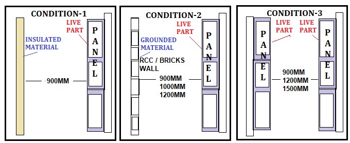
  • Equipment that may need examination, adjust­ment, servicing, or maintenance while energized must have working space which is measured from the enclosure front, must not be less than the distances con­tained in Table 110.26(A)(1).

 (1) DEPTH OF WORKING SPACE.

Table 110.26(A)(1) Working Space

Voltage-to-Ground One side of working Space having Pnel Exposed live parts and other side of Working Space having no live or grounded parts (including concrete, brick, or tile walls) One side of working Space having Panel Exposed live parts and other side of Working Space having live or grounded parts (including concrete, brick, or tile walls) Exposed live parts on both sides of the working space. 0 To 150V 3 Foot (900MM) 3 Foot (900MM) 3 Foot (900MM) 151V To 600V 3 Foot (900MM) 3.5 Foot (1000MM) 4 Foot (1200MM) 601V TO 1000V 3 Foot (900MM) 4 Foot (1200MM) 5 Foot (1500MM)
A

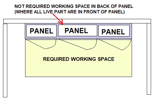
(a) Rear and Sides. Working space isn’t required for the back or sides of assemblies where all connections and all renewable or adjustable parts are accessible from the front.

(2) WIDTH OF WORKING SPACE.

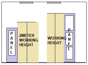
  • The width of the working space must be a minimum of 760MM (30 in) but in no case less than the width of the equipment. * The width of the working space can be measured from left-to-right, from right-to-left, or simply centered on the equipment, and the working space can overlap the working space for other electrical equipment. * In all cases, the working space must be of sufficient width, depth, and height to permit all equipment doors to open 90 degrees.

B

(3) HEIGHT OF WORKING SPACE (HEADROOM).

  • The height of the working space in front of equipment must not be less than 2 Meter (6½ ft) measured from the grade, floor, platform, or the equipment height, whichever is greater. * Equipment such as raceways, cables, wireways, cabinets, panels, and so on, can be located above or below electrical equipment, but must not extend more than 6 in. into the equipment’s working space.

D

(B) LIMITED ACCESS

  • Where equipment is installed above a lay-in ceiling, there shall be an opening not smaller than 559 mm × 559 mm (22 in. × 22 in.), or in a crawl space, there shall be an accessible opening not smaller than 559 mm × 762 mm (22 in. × 30 in.). * The width of the working space shall be the width of the equipment enclosure or a minimum of 762 mm (30 in.) whichever is greater. * All enclosure doors or hinged panels shall be capable of opening a minimum of 90 degrees. * The space in front of the enclosure shall comply with the depth requirements of Table 110.26(A)(1). * The maximum height of the working space shall be the height necessary to install the equipment in the limited space. A horizontal ceiling structural member or access panel shall be permitted in this space.

 (C) ENTRANCE TO AND EGRESS FROM WORKING SPACE.

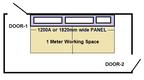
  • (1) Minimum Required: At least one entrance of sufficient area must provide access to and egress from the working space. * (2) Large Equipment: An entrance to and egress from each end of the working space of for electrical equipment rated 1,200A or more and over 6 ft wide is required an entrance of Not Less than 600MM Wide and 1800MM Height at each end of Working Place.

E

  • A single entrance to and egress from the required working space is permitted where either of the following conditions is met: * (a) Unobstructed Egress. Only one entrance is required where the location permits a continuous and unobstructed way of egress travel. * (b) Double Workspace. Only one entrance is required where the required working space depth is doubled, and the equipment is located so the edge of the entrance is no closer than the required working space distance.

F

  • (3) Personnel Doors: If equipment with overcurrent or switch­ing devices rated 1,200A or more is installed, personnel door(s) for entrance to and egress from the working space located less than 25 ft from the nearest edge of the working space must have the door(s) open in the direction of egress and be equipped with panic hardware or other devices that open under simple pressure
G

C

Working Space for Electrical Equipment / Panel-PART-2

WORKING SPACE FOR ELECTRICAL EQUIPMENTS / PANELS (PART-2)

(D) ILLUMINATION:

  • Service equipment, switchboards, panel boards, as well as motor control centers located in indoors must have illumination and controlled by automatic means only.

(E) DEDICATED EQUIPMENT SPACE:

  • Switchboards, panel boards, and motor control centres must have dedicated equipment space as follows:

(1) INDOORS (110.26 (E))

(A) DEDICATED ELECTRICAL SPACE:

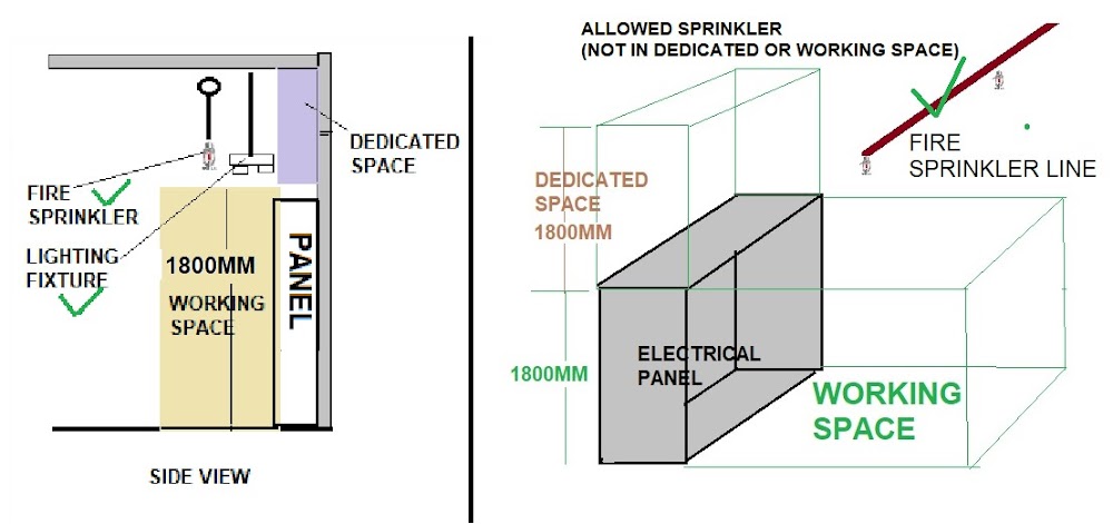
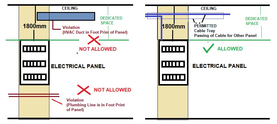
  • a dedicated electrical space is defined as the space equal to the width and the depth of the equipment extending from the floor to a height of 1.8 m above the equipment or the structural ceiling, whichever is lower. * No piping, ducts, or other foreign equipment can be installed in this dedicated Electrical footprint space. * Busways, conduits, raceways, and cables are permitted to enter through this Dedicated Electrical Space / zone.

A

(B) FOREIGN SYSTEMS:

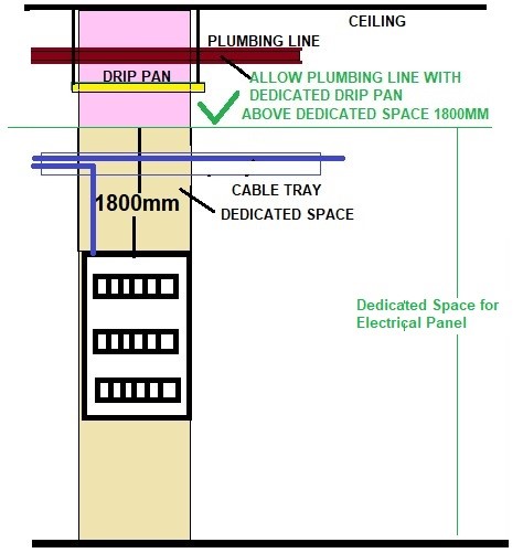
  • Foreign systems can be located above the ded­icated space if proper protection is installed to prevent damage to the elec­trical equipment from condensation, leaks, or breaks in the foreign systems, * This can be achieved by installation of simple as a drip-pan.

B

(C) SPRINKLER PROTECTION (110.26(E)):

  • SPRINKLER PROTECTION SHALL BE PERMITTED IN THE AREA ABOVE THE DEDICATED ELECTRICAL SPACE IF THE ELECTRICAL EQUIPMENT IS PROPERLY PROTECTED AGAINST WATER LEAKS OR BREAKS IN THE SPRINKLER SYSTEM.

  • Sprinkler System shall not be permitted in Working Space of Electrical Equipment. * Hence the sprinkler piping can run above the dedicated electrical space 1.8 m above equipment as long as the Electrical equipment below is protected from leaks, condensation, and even breaks by using dedicated Drip Pan. * But drip pans which may create an obstruction to sprinkler system discharge. So, it is always advisable to avoid locating sprinklers and sprinkler piping directly above electrical equipment and sprinklers and sprinkler piping are not permitted to be located directly within the working space for the equipment as shown in the figure. 

C

  • Where all of the following conditions are met, sprinklers shall not be required in electrical rooms * (1) The room is dedicated to electrical equipment only. * (2) Only dry-type or liquid-type with listed K-class fluid electrical equipment is used. * (3) Equipment is installed in a 2-hour fire-rated enclosure including protection for penetrations. * (4) Storage is not permitted in the room.

(D) SUSPENDED CEILINGS:

  • A dropped, Suspended or other similar hanging ceiling that does not add strength to the building structure is permitted to be located directly in the dedicated space, because they are not considered structural ceilings. Building structural members are also permitted in this space.

(2) OUTDOOR:

  • Outdoor Electrical installations must comply with the following:

(A) INSTALLATION REQUIREMENTS:

  • Switchboards, switchgear, panel boards installed outdoors must be Installed in identified enclosures * Protected from accidental contact by unauthorized personnel, or by vehicular traffic. * Protected by accidental spillage or leakage from piping systems

(B) WORK SPACE.

  • The working clearance space shall include the zone described in 110.26(A). No architectural appurtenance or other equipment shall be located in this zone. * Exception: Structural overhangs or roof extensions shall be permitted in this zone.

(C) DEDICATED EQUIPMENT SPACE OUTDOOR.

  • The footprint space (width and depth of the equipment) extending from grade to a height of 6 ft above the equipment must be dedicated for the electrical installation. * No piping, ducts, or other equipment foreign to the electrical installation can be installed in this dedicated footprint space.

(F) LOCKED ELECTRICAL EQUIPMENT ROOMS OR ENCLOSURES.

  • Electrical equipment rooms and enclosures housing electrical equipment can be controlled by locks because they are still considered to be accessi­ble to qualified persons who require access.

ENCLOSURE FOR ELECTRICAL INSTALLATIONS (110.31)

  • Electrical installations in an Electrical Room, or closed area surrounded by a wall, screen, or fence shall be access or controlled by a lock(s) or other approved manners. * Electrical Installation Area (Indoor and Outdoor) shall be accessible to qualified persons only. * The type of enclosure used shall be designed and constructed according to the nature and degree of the hazard(s) associated with the installation. * For Outdoor Type Electrical installations shall be covered by Fence.

(A) FENCE:

  • A fence shall not be less than 2.1 m (7 ft) in height or a combination of 1.8 m (6 ft) or more of fence fabric and a 300 mm (1 ft) or more extension utilizing three or more strands of barbed wire or equivalent. * The distance from the fence to live parts shall be not less than given in Table 110.31.

Min. Distance from Fence to Live Par…

Typical Earthing Resistance Value

TYPICAL EARTHING RESISTANCE VALUE

  • The resistance offered by the earth electrode to the flow of current into the ground is known as the earth resistance or resistance to earth. * Ideally a ground resistance should be of zero ohms but It is always greater than Zero .System ground resistances can be reduce by the use of a number of individual electrodes connected together. * Total earthing resistance is the sum of the resistance of earth lead wires, Contact resistance between the surface of the earth electrode and the soil and The resistance of the body of the soil surrounding the earth electrode. * The value of earthing resistance varies on the Type of Soil, Soil characteristic, soil resistivity and the climatic condition. Moisture content in soil plays a vital role in the soil resistivity. value of individual earthing pit resistance is not so important. Different codes specifies the required value of earthing system. * Electrical Systems can work with earth resistance of 20 ohms, though generally 10 ohms is the specified Maximum limit. * But communication systems need very stringent limit, typically one ohm. This is because the higher the ground resistance, higher would be noise interference in the systems.

USAID

a) Power stations (generating station)

0.5 ohms

b) EHT Sub-station

1.0 ohms

c) 33 KV Stations

2.0 ohms

d) D/t Structure

5.0 ohms

e) Tower Foot resistance

10.0 ohms

IEEE STANDARD 142

Chapter: 4.1.3 , page 164 For industrial plant substations and buildings and large commercial installations.

1Ω to 5 Ω

Resistances of less than 1 ohm may be obtained using a number of individual electrodes connected together. Such a low resistance is only required for large substations, transmission lines, or generating stations.

National Electric code (NEC) 2011, (IS SP30 Chapter 14 -India)

Chapter: 3.0.9 unless otherwise specified ,It is recommended that the value of any earth system resistance shall not be more than

5Ω

IS 3043 (India)

Chapter: 22.2.3 The continuity resistance of the earth return path through the earth grid should be maintained as low as possible and in no case greater than

1Ω

This applicable for main earth grid connected with the transformer/return path

Oil Industry Safety Directorate Government of India (OISD STANDARD – 137)

Chapter: (7. ii. b) Allowable earth-Resistance Values Allowable earth-Resistance Values The resistance value of an earthing system to general mass of the earth should not exceed. For electrical systems and metallic structures.

4Ω

For storage tanks.

7Ω

for main earth grid, and bonding connections between joints in pipelines and associated facilities.

1Ω

for each electrode to the general mass of the earth

2Ω

IS 2309 (india) / BS 7430:1998

Clause:12.3.1 Page 32,Resistance to Earth Lightning arrestors ground resistance for Protection of buildings and allied structures is

10Ω

An earth electrode should be connected to each down conductor. Each of these earths should have a resistance not exceeding the product given by 10 a multiplied by the number of earth electrodes to be provided. The whole of the lightning protective system, including any ring earth, should have a combined resistance to earth not exceeding 10 Ω without taking account of any bonding. If the value obtained for the whole of the lightning protective systems exceeds 10 Ω, a reduction can be achieved by extending or adding to the electrodes or by interconnecting the individual earth terminations of the down conductors by a conductor installed below ground, sometimes referred to as a ring conductor

IS 2689:1989

Table 4 page 28 (Reaffirmed March 2010) Lightning arrestors ground resistance for Protection of buildings and allied structures is

10Ω

NEC 250.56

Clause: 250.53 Grounding Electrode System Installation. The maximum resistance for a single electrode consisting of a rod, pipe, or plate.

25Ω

If a higher resistance is obtained for a single electrode, a second electrode of any of the types specified in the NEC is required. This should not be interpreted to mean that 25 ohm is a satisfactory resistance value for a grounding system.

IEEE Std 80-2000 (Revision of IEEE Std 80-1986)

the evaluation of ground resistance for the most transmission and other large substations, the ground resistance is usually about

1Ω or less

In smaller distribution substations, the usually acceptable range is

1Ω to 5Ω

NFC 17-102, July 1995

that the resistance value measured using conventional equipment should be

1Ω or less

This resistance should be measured on the earthing termination insulated from any other conductive component.

IEC 62305-1

edition 2.0 – 2010-12 the conventional earthing impedance related to the earth termination system is (*for the soil resistivity less than or equal to 100 Ω)

4 Ω

Ministry of Railways- Government of India

The acceptable Earth Resistance at earth MEEB b…

Earthing Strip / Wire / Pit Quick Reference (Part-1)

EARTHING STRIP /WIRE / PIT QUICK REFERENCE-(PART-1)

TRANSFORMER-EARTHING WIRE / STRIP SIZE:

Size of T.C or DG

Body Earthing

Neutral Earthing

<315 KVA 25×3 mm Cu / 40×6 mm GI Strip 25×3 mm Cu Strip 315 KVA to 500 KVA 25×3 mm Cu / 40×6 mm GI Strip 25×3 mm Cu Strip 500 KVA to 750 KVA 25×3 mm Cu / 40×6 mm GI Strip 40×3 mm Cu Strip 750 KVA to 1000 KVA 25×3 mm Cu / 40×6 mm GI Strip 50×3 mm Cu Strip

 MOTOR- EARTHING WIRE / STRIP SIZE:

Size of Motor

Body Earthing

< 5.5 KW

85 SWG GI Wire

5.5 KW to 22 KW

25×6 mm GI Strip

22 KW to 55 KW

40×6 mm GI Strip

55 KW

50×6 mm GI Strip

 PANEL- EARTHING WIRE / STRIP SIZE:

Type of Panel

Body Earthing

Lighting & Local Panel

25×6 mm GI Strip

Control & Relay Panel

25×6 mm GI Strip

D.G & Exciter Panel

50×6 mm GI Strip

D.G & T/C Neutral

50×6 mm Cu Strip

 ELECTRICAL EQUIPMENT EARTHING:

Equipment

Body Earthing

LA (5KA,9KA)

25×3 mm Cu Strip

HT Switchgear

50×6 mm GI Strip

Structure

50×6 mm GI Strip

Cable Tray

50×6 mm GI Strip

Fence / Rail Gate

50×6 mm GI Strip

 EARTHING WIRE (AS PER BS 7671)

Cross Section Area of Phase, Neutral Conductor(S) mm2

Minimum Cross Section area of Earthing Conductor (mm2)

S<=16

S (Not less than 2.5 mm2)

16<S<=35

16

S>35

S/2

 EARTHING RESISTANCE VALUE:

Earthing Resistance Value

Power Station 0.5 Ω Sub Station Major 1.0 Ω Sub Station Minor 2.0 Ω Distribution Transformer 5.0 Ω Transmission Line 10 Ω Single Isolate Earth Pit 5.0 Ω Earthing Grid 0.5 Ω As per NEC Earthing Resistance should be <5.0 Ω

Earthing Strip / Wire / Pit Quick Reference (As per CPWD) (Part-2)

EARTHING STRIP /WIRE / PIT QUICK REFERENCE (AS PER CPWD) (PART-2)

Earthing Strip for Sub-Station Equipment

CPWD-TABLE VIII

Type of Installation Earth Electrode Earth Strip Indoor sub-station with HT panel, Transformer capacity up to 1600 KVA, LT panel, D.G Set. Copper Plate 25 x 5 mm Copper Strip Indoor sub-station with HT panel, Transformer capacity above 1600 KVA, LT panel, D.G Set Copper Plate 32 x 5 mm Copper Strip HT Outdoor sub-station Copper Plate 25 x 5 mm Copper Strip LT Indoor sub-station with generator Copper Plate 25 x 5 mm Copper Strip LT switch room with Main LT D.B Copper Plate 20 x 3 mm Copper Strip

Neutral Earthing of Transformers and Generators

CPWD-TABLE VIII

Type of Installation Earth Electrode Earth Strip for Neutral Transformer of capacity up to 1600 KVA Copper Plate 25 x 5 mm Copper strip Transformer of capacity above 1600 KVA Copper Plate 32 x 5 mm Copper strip Generating set of all capacity Copper Plate 26 x 5 mm Copper strip Type of Installation Earth Electrode Earth Strip for Neutral Transformer of capacity up to 1600 KVA Copper Plate 25 x 5 mm Copper strip

Earthing Strip for Bus Trunking and Rising Main

CPWD-TABLE VIII

Type of Installation Material of Main Conductor Earth Strip Bus trunking up to 2500 Amp capacity Copper/ Aluminum 2 No 25 x 5 mm Copper Strip Bus trunking above 2500 Amp capacity Copper/ Aluminum 2 No 32 x 5 mm Copper Strip Bus trunking for generating set and LT panel Copper/ Aluminum 2 No 25 x 5 mm Copper Strip Rising main up to 400 Amp capacity Copper/ Aluminum 2 No 20 x 5 mm Copper Strip Rising main above 400 Amp and up to 800 Amp Copper/ Aluminum 2 No 20 x 3 mm Copper Strip

The Size of Earthing conductors

As per CPWD

Size of phase conductor Size of Earthing conductor of the same material as phase conductor Up to 4 sq.mm. Same size as that of phase conductor Above 4 sq.mm. up to 16 sq.mm. Same size as that of phase conductor Above 16 sq.mm. up to 35 sq.mm. 16 sq.mm. Above 35 sq.mm. Half of the phase conductor

Materials and Sizes of Earth Electrodes

CPWD-TABLE IX

Type of Electrodes Material Size Pipe GI medium class 40 mm dia 4.50 m long (without any joint) Plate (i) GI 60 cm x 60 cm x 6 mm thick (ii) Copper 60 cm x 60 cm x 3 mm thick Strip (i) GI 100 sq. mm section (ii) Copper 40 sq. mm section Conductor (i) Copper 4 mm dia (8 SWG) Note : Galvanization of GI items shall conform to Class IV of IS 4736 : 1986.

Minimum Sizes of Earthing Conductors for Use Above Ground

CPWD- TABLE X

Material and Shape Minimum Size Round copper wire or copper clad steel wire 6 mm diameter Stranded copper wire 50 sq. mm or (7/3.00 mm dia) Copper strip 20 mm x 3 mm Galvanized iron strip 20 mm x 3 mm Round Aluminum wire 8 mm diameter Aluminum strip 25 mm x 3 mm

Minimum Sizes of Earthing Conductors for Use Below Ground

CPWD- TABLE XI

Material and Shape Minimum Size Round copper wire or copper clad steel wire 8 mm diameter Copper strip 32 mm x 6 mm Round galvanized iron wire 10 mm x 6 mm Galvanized iron strip 32 mm x 6 mm

Selection of Type of Earthing Electrodes

As per CPWD

Type of electrode Application GI pipe Internal electrical installations like Distribution Board and Meter Boards (in residential quarters), feeder pillars and poles etc. GI plate (i) For Fire Fighting pumps and water supply pumps. (ii) Lightning conductors. Copper plate Neutral earthing of transformers/ generating sets. Strip/ Conductor Locations where it is not possible to use other types.

Number of Earth Electrodes

As per CPWD

Equipment No of Earthing For neutral earthing of each transformer 2 sets For body earthing of all the transformers, 2 sets HT/LT Panels and other electrical equipment in the Sub-station/ power house For neutral earthing of each generating set 2 sets For body earthing of all the generating sets, 2 sets LT panels, other electrical equipment in the generator room

Size of protective conductor

As per CPWD

Size of phase conductor Size of protective conductor of the same material as phase conductor Up to 16 sq.mm. Same as Phase Conductor Size 16 to 35 sq.mm. 16 sq.mm. 35 sq.mm Half Size of Phase Conductor

Earthing Points

As per CPWD

Earthing Description Location for Earth Electrodes Normally an earth electrode shall not be located closer than 1.5 m from any building. Installation of Pipe Pipe electrode shall be buried in the ground vertically with its top at not less than 20 cm below the ground level Installation of Plate Plate electrode shall be buried in ground with its faces vertical, and its top not less than 3.0 m below the ground level. The strip or conductor The strip or conductor electrode shall be buried in trench not less than 0.5 m deep More Earthing Electrode When more than one electrode (plate/pipe) is to be installed, a separation of not less than 2 m shall be maintained between two adjacent electrodes. Earthing Electrode If the electrode cannot be laid in…

Difference between Bonding, Grounding and Earthing

DIFFERENCE BETWEEN BONDING, GROUNDING AND EARTHING

INTRODUCTION:

  • One of the most misunderstood and confused concept is difference between Bonding, Grounding and Earthing. Bonding is more clear word compare to Grounding and Earthing but there is a micro difference between Grounding and Earhing. * Earthing and Grounding are actually different terms for expressing the same concept. Ground or earth in a mains electrical wiring system is a conductor that provides a low impedance path to the earth to prevent hazardous voltages from appearing on equipment. Earthing is more commonly used in Britain, European and most of the commonwealth countries standards (IEC, IS), while Grounding is the word used in North American standards (NEC, IEEE, ANSI, UL). * We understand that Earthing and Grounding are necessary and have an idea how to do it but we don’t have crystal clear concept for that. We need to understand that there are really two separate things we are doing for same purpose that we call Grounding or Earthing. * The Earthing is to reference our electrical source to earth (usually via connection to some kind of rod driven into the earth or some other metal that has direct contact with the earth). * The grounded circuits of machines need to have an effective return path from the machines to the power source in order to function properly (Here by Neutral Circuit). * In addition, non-current-carrying metallic components in a System, such as equipment cabinets, enclosures, and structural steel, need to be electrically interconnected and earthed properly so voltage potential cannot exist between them. However, troubles can arise when terms like “bonding,” “grounding,” and “earthing” are interchanged or confused in certain situations. * In TN Type Power Distribution System, in US NEC (and possibly other) usage: Equipment is earthed to pass fault Current and to trip the protective device without electrifying the device enclosure. Neutral is the current return path for phase. These Earthing conductor and Neutral conductor are connected together and earthed at the distribution panel and also at the street, but the intent is that no current flow on earthed ground, except during momentary fault conditions. Here we may say that Earthing and grounding are nearly same by practice. * But In the TT Type Power Distribution System (In India) Neutral is only earthed (here it is actually called Grounding) at distribution source (at distribution transformer) and Four wires (Neutral and Three Phase) are distributed to consumer. While at consumer side all electrical equipments body are connected and earthed at consumer premises (here it is called Earthing). Consumer has no any permission to mix Neutral with earth at his premises here earthing and grounding is the different by practice. * But in both above case Earthing and Grounding are used for the same Purpose. Let’s try to understand this terminology one by one.

BONDING:

  • Bonding is simply the act of joining two electrical conductors together. These may be two wires, a wire and a pipe, or these may be two Equipments. * Bonding has to be done by connecting of all the metal parts that are not supposed to be carrying current during normal operations to bringing them to the same electrical potential. * Bonding ensures that these two things which are bonded will be at the same electrical potential. That means we would not get electricity building up in one equipment or between two different equipment. No current flow can take place between two bonded bodies because they have the same potential. * Bonding, itself, does not protect anything. However, if one of those boxes is earthed there can be no electrical energy build-up. If the grounded box is bonded to the other box, the other box is also at zero electrical potential. * It protects equipment & Person by reducing current flow between pieces of equipment at different potentials. * The primary reason for bonding is personnel safety, so someone touching two pieces of equipment at the same time does not receive a shock by becoming the path of equalization if they happen to be at different potentials. * The Second reason has to do with what happens if Phase conductor may be touched an external metal part. The bonding helps to create a low impedance path back to the source. This will force a large current to flow, which in turn will cause the breaker to trip. In other words, bonding is there to allow a breaker to trip and thereby to terminate a fault. * Bonding to electrical earth is used extensively to ensure that all conductors (person, surface and product) are at the same electrical potential. When all conductors are at the same potential no discharge can occur.

EARTHING:

  • Earthing means connecting the dead part (it means the part which does not carries current under normal condition) to the earth for example electrical equip…
Cover image
D

What is Earthing

WHAT IS EARTHING

INTRODUCTION:

The main reason for doing earthing in electrical network is for the safety. When all metallic parts in electrical equipments are grounded then if the insulation inside the equipments fails there are no dangerous voltages present in the equipment case. If the live wire touches the grounded case then the circuit is effectively shorted and fuse will immediately blow. When the fuse is blown then the dangerous voltages are away.

PURPOSE OF EARTHING:

(1)Â SAFETY FOR HUMAN LIFE/ BUILDING/EQUIPMENTS:

  • To save human life from danger of electrical shock or death by blowing a fuse i.e. To provide an alternative path for the fault current to flow so that it will not endanger the user * To protect buildings, machinery & appliances under fault conditions. * To ensure that all exposed conductive parts do not reach a dangerous potential. * To provide safe path to dissipate lightning and short circuit currents. * To provide stable platform for operation of sensitive electronic equipments  i.e. To maintain the voltage at any part of an electrical system at a known value so as to prevent over current or excessive voltage on the appliances or equipment .

(2)Â OVER VOLTAGE PROTECTION:

  • Lightning, line surges or unintentional contact with higher voltage lines can cause dangerously high voltages to the electrical distribution system. Earthing provides an alternative path around the electrical system to minimize damages in the System.

(3)Â VOLTAGE STABILIZATION:

  • There are many sources of electricity. Every transformer can be considered a separate source. If there were not a common reference point for all these voltage sources it would be extremely difficult to calculate their relationships to each other. The earth is the most omnipresent conductive surface, and so it was adopted in the very beginnings of electrical distribution systems as a nearly universal standard for all electric systems.

CONVENTIONAL METHODS OF EARTHING:

(1)Â PLATE TYPE EARTHING:

  • Generally for plate type earthing normal Practice is to use * Cast iron plate of size 600 mm x600 mm x12 mm. OR * Galvanized iron plate of size 600 mm x600 mm x6 mm. OR * Copper plate of size 600 mm * 600 mm * 3.15 mm * Plate  burred at the depth of 8 feet in the vertical position and GI strip of size 50 mmx6 mm bolted with the plate is brought up to the ground level. * These types of earth pit are generally filled with alternate layer of charcoal & salt up to 4 feet from the bottom of the pit.

(2)Â PIPE TYPE EARTHING:

  • For Pipe type earthing normal practice is to use * GI pipe [C-class] of 75 mm diameter, 10 feet long welded with 75 mm diameter GI flange having 6 numbers of holes for the connection of earth wires and inserted in ground by auger method. * These types of earth pit are generally filled with alternate layer of charcoal & salt or earth reactivation compound.

METHOD FOR CONSTRUCTION OF EARTHING PIT (INDIAN ELECTRICITY BOARD):

  • Excavation on earth for a normal earth Pit size is 1.5M X 1.5M X 3.0 M. * Use 500 mm X 500 mm X 10 mm GI Plate or Bigger Size for more Contact of Earth and reduce Earth Resistance. *  Make a mixture of Wood Coal Powder Salt & Sand all in equal part *  Wood Coal Powder use as good conductor of electricity, anti corrosive, rust proves for GI Plate for long life. * The purpose of coal and salt is to keep wet the soil permanently. * The salt percolates and coal absorbs water keeping the soil wet. * Care should always be taken by watering the earth pits in summer so that the pit soil will be wet. * Coal is made of carbon which is good conductor minimizing the earth resistant. * Salt use as electrolyte to form conductivity between GI Plate Coal and Earth with humidity. * Sand has used to form porosity to cycle water & humidity around the mixture. * Put GI Plate (EARTH PLATE) of size 500 mm X 500 mm X 10 mm in the mid of mixture. * Use Double GI Strip size 30 mm X 10 mm to connect GI Plate to System Earthling. *  It will be better to use GI Pipe of size 2.5″ diameter with a Flange on the top of GI Pipe to cover GI Strip from EARTH PLATE to Top Flange. * Cover Top of GI pipe with a T joint to avoid jamming of pipe with dust & mud and also use water time to time through this pipe to bottom of earth plate. * Maintain less than one Ohm Resistance from EARTH PIT conductor to a distance of 15 Meters around the EARTH PIT with another conductor dip on the Earth at least 500 mm deep. * Check Voltage between Earth Pit conductors to Neutral of Mains Supply 220V AC 50 Hz it should be less than 2.0 Volts.

FACTORS AFFECTING ON EARTH RESISTIVITY:

(1) SOIL RESISTIVITY:    

  • It is the resistance of soil to the passage of electric current. The earth resistance value (ohmic value) of an earth pit depends on soil resistivity. It is the resistance of the soil to the passage of electric current. * It var…