Site logo
Electrical Engineering Academy
D

Single Earthed Neutral and Multi Earthed Neutral.

SINGLE EARTHED NEUTRAL AND MULTI EARTHED NEUTRAL.

SINGLE EARTHED NEUTRAL AND MULTI EARTHED NEUTRAL:

  • In Distribution System Three Phase load is unbalance and non linear so The Neutral plays an important role in Distribution system. * Generally, distribution networks are operated in an unbalanced configuration and also service to consumers. This causes current flowing through neutral conductor and voltage dropping on neutral wire. The unbalance load and excessive current in neutral wire is one of the issues in three phase four-wire distribution systems that causes voltage drop through neutral wire and makes tribulations for costumers. The existence of Neutral earth Voltage makes unbalance in three phase voltages for three phase customers and reduction of phase to neutral voltage for single phase customers. * MULTI-GROUNDED three-phase four-wire service is widely adopted in modern power distribution systems due to having lower installation costs and higher sensitivity of fault protection than three-phase three-wire service. The neutrals play an important role in power quality and safety problems. * The multi grounded neutral system is the predominant electrical distribution system used in the United States. * It allow an uncontrolled amount of electric current to flow over the earth unrestrained, posing the potential of harm to the public and to animals causing electric shocks and is presumed responsible for undetected electrocutions. * The protective grounding used in low voltage,600-volt and below, applications will be described and used to explain the hazards involved with the present day multi grounded neutral distribution System, used in the United States. This will allow the reader to see the parallels between the safe low voltage distribution system and the dangerous medium voltage multi grounded neutral distribution system. * The reasons for the development of the three phase, four-wire, multi-grounded systems involve a combination of safety and economic considerations. The three-phase, four-wire multi-grounded design has been successfully used for many years and is well documented in the standards including the National Electrical Code (NEC). * It is Crucial decisions to adopt Multi Grounded Neutral System “save money” by the adoption of the multi grounded neutral electrical distribution system in the cost of the public’s safety.

 MULTI GROUNDED NEUTRAL SYSTEM (MEN):

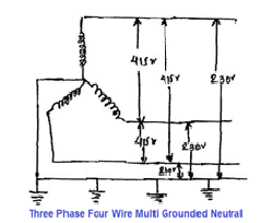
  • Fig shows the multi-grounded neutral systems commonly used by the electric utilities in North America. The neutral grounding reactor is used by some utilities to reduce the available ground fault current while at the same time still maintaining an effectively grounded system. * The multiple earthed neutral (MEN) system of earthing is one in which the low voltage neutral conductor is used as the low resistance return path for fault currents and where its potential rise is kept low by having it connected to earth at a number of locations along its length. The neutral conductor is connected to earth at the distribution transformer, at each consumer’s installation and at specified poles or underground pillars. The resistance between the neutral conductor of the distribution system and the earth must not exceed 10 ohms at any location. * NEC Article 250 Part X Grounding of Systems and Circuits 1 kV and Over (High Voltage) * (A) Multiple Grounding: The neutral of a solidly grounded neutral system shall be permitted to be grounded at more than one point. * (B) Multi-grounded Neutral Conductor: Ground each transformer, Ground at 400 m intervals or less, Ground shielded cables where exposed to personnel contact.

SINGLE GROUNDED NEUTRAL:

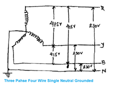
  • Fig Show Single Grounded Neutral Which is different from Multi Grounded System .Figure shows the neutral also connected to earth, but the neutral conductor is extended along with the phase conductors. The configuration shown in figure allows electrical loads, transformers to be placed between any of the three phase conductors, phase-to-phase and/or phase-to-neutral. * This connection, phase to neutral will force electric current to flow over the neutral back to the transformer. So far, this electrical connection is acceptable, as long as the neutral is insulated or treated as being potentially energized, but modifications will be made in the future that will negate safety for the public and animals. * The ground connection would typically be located in the distribution substation. This may appear insignificant, but the differences are significant

 ADVANTAGES OF MULTIPLE GROUNDED NEUTRAL SYSTEMS:

(1) Optimize the Size of Surge Arrestor:

  • Surge arresters are applied to a power system based on the line-to-ground voltage under normal condition and abnormal…
D

Method for Installation of Earthing Strip

METHOD FOR INSTALLATION OF EARTHING STRIP

(A) PURPOSE:

  • The method is to explain the procedure, which should be followed to install the Earthing Strip, Earthing Wire, and Earthing accessories as per the specification to achieve the standard requirements of the project.

(B) EQUIPMENT & TOOLS:

  • The equipment that will be used for Installation of Earthing Strip / Wire works are
  1. Ladder 2. Spirit Level 3. Drilling Machine 4. Grinding Machine 5. Cutting Machine 6. Power tools 7. Measure Tape 8. Screwdriver 9. Drill with bits 10. File 11. Galvanizing paint 12. Bitumius Paint

(C) TEST FOR EARTHING STRIP / EARTHING ACCESSORIES:

  • Visual inspection: * Type of Earthing Strip and Accessories Material * Length , Width and thickness of Earthing Strip and Accessories * Galvanization thickness * Galvanization tests to be conduct. * Proper painting / Galvanization and identification numbers of the Earthing Strip and Accessories * The GS Flat to be supplied in 5.5 meters to 13 meters lengths. * The weight of GS Flat * MS flat shall conform to IS 2062 & its latest amendments for steel & Galvanization as per IS 4759 & its Latest amendments * Physical Damages Inspection: * Damage on Earthing Strip and Accessories * Damage on galvanizing * Testing of galvanizing: * Uniformity of coating Thickness Test * TRs not more than five year old shall be reviewed for acceptance.

Hot dip galvanization. (IS 2629) Galvanizing Minimum thickness: Min. weight: MS flats 5mm thick & over 75 microns (minimum) 610 gms. / sq. mtr. MS flats under 5mm thickness 60 microns (minimum) 460 gms. / sq. mtr. Pipes/ conduits with thickness over 5 mm 75 microns (minimum) 610 gms. / sq. mtr Pipes/ conduits with thickness under 5mm 60 microns (minimum) 460 gms. / sq. mtr GI Wire 20 Microns (Medium coated) 150 gms. / sq. mtr.

(D) STORAGE & HANDLING:

  • The Earthing Flat shall be supplied in standard lengths. * Materials should be stored according to a specification which is the maximum 1.5m height from the ground. Suitable support should be provided. The storage should be done in a designated area and proper covering should be provided. * Earthing Strip and Accessories (pre-galvanized, hot dipped galvanized) shall be stored in a dry place, fully enclosed / ventilated store. * When bringing down materials, they should be handled with care and lowered carefully to the ground. They should not be dropped.

(E) PREPARATION FOR EARTHING STRIP / WIRE

  • Check and ensure that the correct size and type of Earthing Strip & accessories are ready for installation. * Ensure that the work area is ready and safe to start the installation of Earthing Strip. * Ensure that Earthing Strip and accessories received from site store for the installation are free of rusty parts and damages.

(F) EARTHING STRIP INSTALLATION:

  • MARKING THE ROUTE:

  • Mark the route of Earthing Strip with marking threads. * The route of Earthing Strip to be coordinated with other services and shall be confirmed. * Minimum space from the building structure and other services to be maintained (200 mm from the nearest point) to facilitate easy handling and maintenance.

  • SATIATING OF EARTHING STRIP / ELECTRODE:

  • Hot-dip galvanized strip steel is aligned on simple straightening machines or on a parallel by hammer.

AA

  • INSTALLATION ON WALL / GROUND:

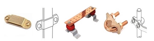
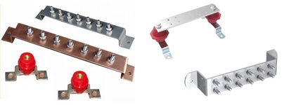
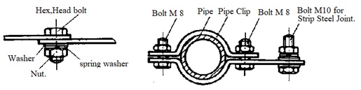
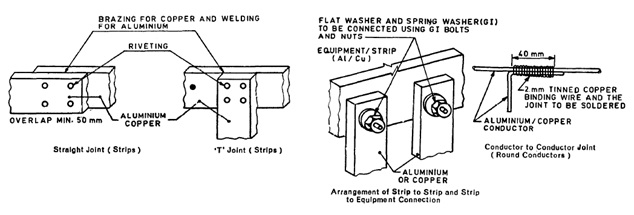
  • GI strips used for earthing shall be minimum 6 mm thick and hot dip galvanized. * If round GI conductors are used it shall have double the calculated area of cross-section. * For installing earth leads on walls, special clamps are employed. They firmly accommodate the earth leads and are easily mounted. They are directly inserted in the wall or screwed to the wall. Fixing should be spaced not more than 1 m apart. * Joints and junctions of earth leads and earthing concentration leads are to warrant a durable, safe and electrically well conductive connection.

AA - Copy

  • Where a Copper conductor is to be joined to GI, the joints should be tinned to prevent electrolytic action. * If atmosphere is corrosive, GI conductors shall not be used for earthing. * Earthing strips may be placed together with underground cables in cable Trench, but the heat from the cable must not be able to dry out the soil. * Earth conductors in trenches having power or multi-core cables should be fixed to the walls near the top (for example, 100 mm from the top). * Copper earth strip supported from or in contact with galvanized steel should be tinned to prevent electrolytic action. * Sharp bends required in aluminum strip should be formed by the use of a bending machine. * Earthing Strip which install below ground should be covered adequate insulating Sleeve for avoid corrosion.

  • EARTHING ELECTRODE (PLATE / PIPE):

  • Minimum distance between earthing electrode (Plate /Pipe) and adjacent civil structure shall be 1.5 meter. * Earthing grid should be run at …

Cover image
D

Methods of Earth Resistance Testing (Part-1)

METHODS OF EARTH RESISTANCE TESTING (PART-1)

INTRODUCTION:

  • The measurement of ground / Earth resistance for an earth electrode is very important for not only for human safety but also for preventing damages of equipment, industrial plants and to reduce system downtime. * It also provides protection against natural phenomenon such as lightning stock by providing path to the lightning current to the ground. * Ground resistance is the measurement of the resistance between conducting connection and earth Soil. * Earth Resistance should be Low as possible to provide low resistance path to leakage current to the earth. * Ground resistance depends on grounding electrode selection, soil resistivity, soil contact, and other factors

 DIFFERENCE BETWEEN GROUND RESISTANCE AND GROUND RESISTIVITY

  • Ground / Earth Resistance: * Ground Resistance is the resistance (Which oppose of current flow) of an installed earthing electrode system. * It is the resistance between a buried electrode and the surrounding soil. * It is measured in * Ground Resistance is measured with a four-point, three-point or clamp on tester. * Ground / Earth Resistivity: * Ground resistivity is a measurement of how much the soil resists the flow of electricity. * Ground resistivity is the electrical properties of the soil for conducting current. * It indicates how good the soil /Earth conducts electric currents. For the lower the resistivity, the lower the earth electrode resistance at that location. * Ground resistivity is theoretical resistance of a cylinder of earth Piece having a cross-section area of 1 Sq. meter. * Ground resistivity (ρ)is measured in Ohm centimeters. * Ground resistivity has nothing to deal with any installed electrical structure, but is a pure measurement of the electrical conductivity of the soil itself. * Ground resistivity is measured with a four-point tester. * Ground resistivity varies significantly according to the region, season and the type of soil because it depends on the level of humidity and the temperature (frost or drought increase it).

PURPOSE OF MEASUREMENT OF EARTH RESISTIVITY:

  • Earth resistivity measurements have a Main three purpose. * Earth resistivity data is used to use survey for Surface of Land to identifying locations, depth to bedrock and other geological phe­nomena. * Earth resistivity data is used for protective anticorrosion treatment of underground pipelines, because Earth resistivity is direct related on the degree of corro­sion of underground pipelines. Lower in resistivity increase in corrosion of Underground Pipes. * Earth resistivity directly affects the design of an Earthing system. When we design an Earthing system, it is advisable to locate the area of lowest soil resistivity to achieve the most economical grounding installation. If the lower the soil resistivity value, the lower the grounding electrode resistance.

EARTH RESISTIVITY DEPENDS ON:

  • There are various that affect the ground resistance of a ground system

(1) Diameter of Ground Rod:

  • Increasing the diameter of the ground electrode has very little effect in lowering the resistance. * Doubling diameter of ground rod reduces resistance only 10%. * Using larger diameter ground rods is mainly a strength issue. In rocky conditions, a larger diameter ground rod might be advantageous.

(2) Depth of Ground Rod:

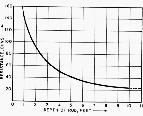
  • As per NEC code minimum ground electrode length of 2.5 meters (8.0 feet) to be in contact with the soil. * Doubling depth of Rod theoretically reduces resistance 40%. * Earthing Spike (electrodes) deeper is a very effective way to lower Earthing resistance. * Actual reduction of resistance depends on soil resistivity encountered in multi-layered soils. * The resistance decreases rapidly as the length of the electrode increases and less rapidly as the diameter increases.

(3) Spacing of Ground Rod:

  • Earth resistance decrease when distance between adjustments earthing Rod is twice the length of the rod in Ground (in good soil).

t

Probe Spacing Probe distance (m) Soil resistance, Re (Ω) Soil resistivity, ρρ (Ω m) 0.3 14.75 27.79 0.6 7.93 29.88 0.9 6.37 36.00 1.2 4.36 32.86 1.5 4.31 40.60

(4) No of Ground Rods:

  • Using multiple ground electrodes provides another way to lower ground resistance. * More than one electrode is driven into the ground and connected in parallel to lower the resistance. * The spacing of additional rods must be at least equal to the depth of the driven rod. * Two well-spaced rods driven into the earth provide parallel paths and act as two resistances in parallel. However the rule for two resistances in parallel does not apply exactly so the resultant resistance is not one-half the individual rod resistances. * The reduction in Earth resistance for equal resistance rods is * 40 % for 2 rods * 60 % for 3 rods * 66 % for 4 rods

(5) Material & Surface Condition of Ground Rod:

  • Ground…
D

Methods of Earth Resistance Testing (Part-2)

METHODS OF EARTH RESISTANCE TESTING (PART-2)

CAN WE USE AN MEGGER OR MULTIMETER FOR EARTH RESISTIVITY TESTING

  • We cannot use Megger or Mulitimeter for Earth resistivity Testing.

Insulation Tester (Megger):

  • Insulation testers are designed to measure at the opposite end of the resistance by inserting high DC Voltage. * Insulation testers use high test voltages in the kilovolt range. The area between electrode and ground is charged with high DC Voltage and we do not want grounds that measure in megohms. * Ground testers use Low Voltage for testing for operator safety, to low voltages.

Multimeter:

  • However, a Multimeter or continuity test can use very low Voltage between an installed electrode and a reference ground, which is assumed to have negligible. * Low voltage DC can produce a resistance reading between ground and an earth electrode but it is not an accurate measurement. * Multimeter measurement may not be reliable, since reading can be influenced by soil transients, the electrical noise that is generated by utility ground currents trying to get back to the transformer, as well as other sources.

CAN EARTH RESISTANCE REDUCE BY POURING WATER AROUND TEST EARTH PROBE

  • By pouring water is near test probe reduce contact resistance of between probe and ground at some extent. * If there is sufficient contact between probe and ground then pouring water near test probe is never decrease earth resistance of the system. * Earth resistance is the resistance of the ground electrode that is being measured, not that of the test probe. The Test probe is a tool to use measurement of earth resistance. * If the test setup has adequate spacing, the probes will be far enough away outside of the electrical field of the test ground so that watering them has no influence on the test result.

 TEST METHODS FOR MEASURING EARTH RESISTANCE

There are six basic test methods to measure earth resistance

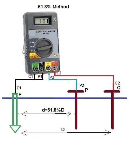
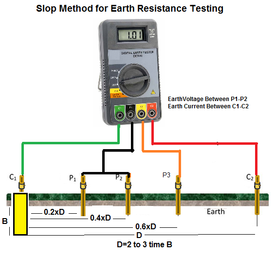
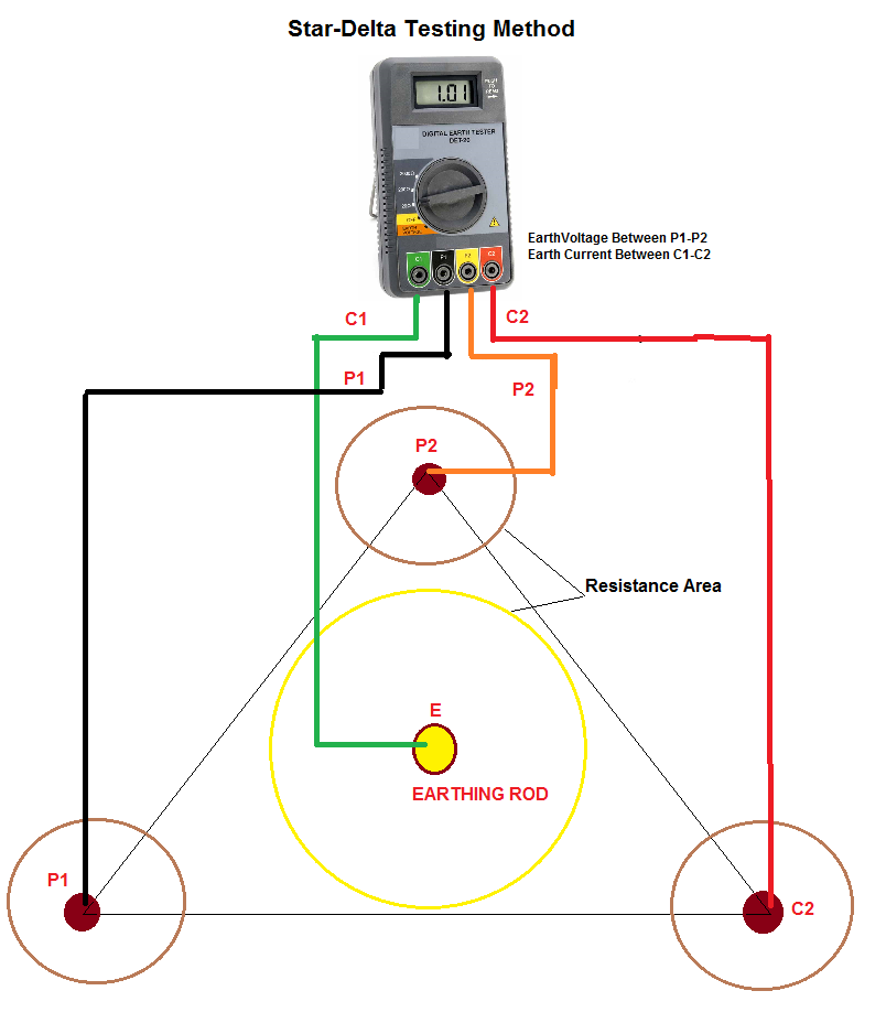
  1. Four Point Method (Wenner Method) 2. Three-terminal Method (Fall-of-potential Method / 68.1 % Method)) 3. Two-point Method (Dead Earth Method) 4. Clamp-on test method 5. Slope Method 6. Star-Delta Method

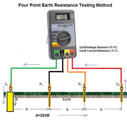
 (1) FOUR POINT METHOD (WENNER METHOD):

  • This method is the most commonly used for measuring soil resistivity,

Required Equipments:

  • Earth Tester (4 Terminal) * 4 No’s of Electrodes (Spike) * 4 No’s of Insulated Wires * Hammer * Measuring Tap

Connections:

  • First, isolate the grounding electrode under measurement by disconnecting it from the rest of the system. * Earth tester set has four terminals, two current terminals marked C1 and C2 and two potential terminals marked P1 and P2. * P1 = Green lead, C1 = Black lead, P2 = Yellow lead, C2 = Red lead * In this method, four small-sized electrodes are driven into the soil at the same depth and equal distance from one another in a straight line. * The distance between earth electrodes should be at least 20 times greater than the electrode depth in ground. * Example, if the depth of each earth electrode is 1 foot then the distance between electrodes is greater than 20 feet. * The earth electrode under measurement is connected to C1 Terminal of Earth Tester. * Drive another potential Earth terminal (P1) at depth of 6 to 12 inches from some distance at C1 Earth Electrode and connect to P1 Terminal of Earth Tester by insulted wire. * Drive another potential Earth terminal (P2) at depth of 6 to 12 inches from some distance at P1 Earth Electrode and connect to P2 Terminal of Earth Tester by insulted wire. * Drive another Current Electrode (C2) at depth of 6 to 12 inches from some distance at P2 Earth Electrode and connect to C2 Terminal of Earth Tester by insulted wire. * Connect the ground tester as shown in the picture.

Testing Procedure:

  • Press START and read out the resistance value. This is the actual value of the ground Resistance of the electrode under test. * Record the reading on the Field Sheet at the appropriate location. If the reading is not stable or displays an error indication, double check the connections. For some meters, the RANGE and TEST CURRENT settings may be changed until a combination that provides a stable reading without error indications is reached. * The Earthing Tester has basically Constant Current generator which injects current into the earth between the two current terminals C1 (E) and C2 (H). * The potential probes P1 & P2 detect the voltage ΔV (a function of the resistance) due to the current injected in the earth by the current terminals C1 & C2. * The test set measures both the current and the voltage and internally calculates and then displays the resistance. R=V/I * If this ground electrode is in parallel or series with other ground rods, the resistance value is the total value of all resistances. * Ground resistance measurem…
D

Methods of Earth Resistance Testing (Part-3)

METHODS OF EARTH RESISTANCE TESTING (PART-3)

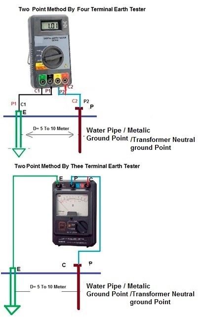
(3) TWO POINT (DEAD EARTH) METHOD.

  • This method is used where the driving of ground spike is neither practical nor possible * To perform this test we have access to a good known ground such as an all metal water pipe. The water pipe should be extensive enough and be metallic throughout without any insulating couplings or flanges. * This method is not as accurate as three-point methods (62% method), as it is particularly affected by the distance between the tested electrode and the dead ground or water pipe

Required Equipment:

  • Earth Tester (4 Terminal or 3 Terminal) * 2 No’s of Insulated Wires * Hammer

Connections:

  • In This method, the resistance of two electrodes in a series is measured by connecting the P1 and C1 terminals to the ground electrode under test; P2 and C2 connect to a separate all-metallic grounding point like a water pipe or building steel. * The earth electrode under test must be far enough away from the secondary grounding point to be outside its sphere of influence.

Testing Procedure:

  • Press START and read out the resistance value. This is the actual value of earthing resistance of the ground electrode under test. * Record the reading on the Field Sheet at the appropriate location. If the reading is not stable or displays an error indication, double check the connections. * Two terminals testing of earth resistance is appropriate for most general purpose testing in normally conductive soil. * Two terminal measurements include less test lead and contact resistance in the measurement and the result will be a reading slightly higher than the true earth resistance. * When measured results are higher than desired or if measurement directives require multi terminal techniques, switch to the 3 or 4 terminal techniques as needed.

1

Advantage:

  • It does Not Require Disconnecting Equipment * This is the simplest way to obtain a ground resistance reading. * It is most effective for quickly testing the connections and conductors between connection points. * Required Less Test Lead. * Required small area for Measurement.

Disadvantage:

  • This is not as accurate as the three-point method and should only be used as a last resort. * Non-metallic (high resistance) return Resistance areas should not overlap.

(4) CLAMP-ON TEST METHOD

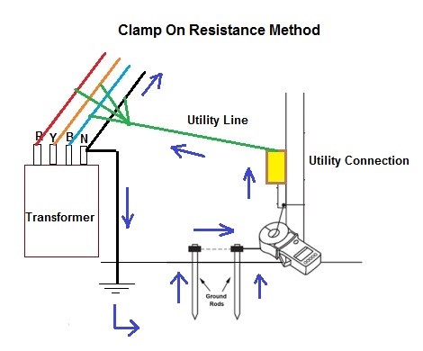
  • For the clamp-on method to be effective there must be a complete grounding circuit in place. The tester measures the complete resistance path (loop) that the signal is taking. All elements of the loop are measured in series. * The Induced Frequency testing or commonly called the “Clamp-On” test is one of the newest test methods for measuring the resistance-to-ground of a grounding system or electrode. * This is Convenient, Quick ,easy and safe Method * It does Not Require Disconnecting Equipment

Required equipment:

  • Clamp-on Ground Resistance Meter. * 2 No’s of Insulated Wires

Connections setup:

2

Testing Procedure:

  • Press START and read out the resistance value. This is the actual value of earthing resistance of the ground electrode under test. * The clamp-on methodology is based on Ohm’s Law (R=V/I). * The source coil inside the clamp of the earth tester inducing the voltage. This voltage is inductively applied to a complete circuit .The resulting current flow in the earthing circuit due to the induced voltage is measured by the current coil installed in the same clamp of the earth tester. * The resistance of the circuit can then be calculated by taking the ratio of the induced voltage and the circulated current in the earthing circuit. * It has to be ensured that the earthing system under test is included in the current circulation loop. The clamp-on earth tester measures the resistance of the path traversed by the induced current. * All elements of the loop are measured in series. This method assumes that only the resistance of the earthing system under test contributes significantly. * A low return path is required for readings. A high resistance return path will yield high readings.

Advantage

  • There is no need to turn off the equipment power or disconnect the earth rod. * Not disconnecting the connections between the earthed body and the metal work of the electrical Earthing Point. * Not dangerous to human life because no any DC current injected in Probe.

Disadvantages:

  • If the frequency of AC current injected into the earth by the tester is the same as that of disturbance current in the earth then accuracy of the readings are seriously affected. * The mutual inductance between the voltage and current loops of the clamp tester may affect accuracy of the readings. * The clamp-on method is only effective in situations with multiple earthing electrodes are in parallel and a closed circuit is available for the current circulation. * It cannot be used on isolated grounds, as there is no …

Quick Reference -Earthing

QUICK REFERENCE -EARTHING

Hot dip galvanization. (IS 2629)

Galvanizing

Minimum thickness:

Min. weight:

MS flats 5mm thick & over

75 microns (minimum)

610 gms. / sq. mtr.

MS flats under 5mm thickness

60 microns (minimum)

460 gms. / sq. mtr.

Pipes/ conduits with thickness & over 5 mm

75 microns (minimum)

610 gms. / sq. mtr

Pipes/ conduits with thickness under 5mm

60 microns (minimum)

460 gms. / sq. mtr

GI Wire

20 Microns (Medium coated)

150 gms. / sq. mtr.

OVERLAPING OF EARTHING STRIP

Size of Earthing Strip

Minimum Over Laping

20×3

20MM

20×6

20MM

25×3

25MM

25×6

25MM

32×6

25MM

40×5

50MM

40×6

50MM

50×6

50MM

50×10

50MM

75×6

50MM

75×10

50MM

NO’S AND SIZE OF NUT BOLT FOR JOINTING EARTHING STRIP

Size of Earthing Strip

Minimum Nut Bolt Required

Minimum Size of Nut Bolt

20×3

2 NO’S

8X25MM

20×6

2 NO’S

8X25MM

25×3

2 NO’S

8X25MM

25×6

2 NO’S

8X25MM

32×6

2 NO’S

8X25MM

40×5

4 NO’S

8X25MM

40×6

4 NO’S

8X25MM

50×6

4 NO’S

10X25MM

50×10

4 NO’S

10X25MM

75×6

4 NO’S

10X25MM

75×10

4 NO’S

10X25MM

Weight of G.I. wire (Steel Tube India)

Gauge Gms.

mm

Weight Kg / Meter.

4

5.892

0.216

6

4.876

0.148

8

4.064

0.103

10

3.251

0.066

12

2.641

0.045

14

2.032

0.026

16

1.625

0.017

Weight of G.I Flat Strip

Sizes in (HxW)

Kgs/Per meter

Application

20×3 mm

0.49

Lighting Arrestor

20×6 mm

0.98

PLC Panel

25×3 mm

0.6

25×5 mm

0.97

25×6 mm

1.3

Control & Relay Panel

32×5 mm

1.21

Lighting Panel & Local Panel

32×6 mm

1.625

Distribution Board

40×3 mm

0.964

Motors 5.5kw-55Kw

40×5 mm

1.476

40×6 mm

1.92

HT switchgear, structures, cable trays & fence, rails, gate and steel column

50×3 mm

1.28

50×5 mm

1.92

50×6 mm

2.56

50×10 mm

4

Transformers Substations

62×6 mm

3.07

65×10 mm

5.2

75×10 mm

6

75×12 mm

7.2

Cable Construction & Cable Selection-Part:4

CABLE CONSTRUCTION & CABLE SELECTION- PART:4

CABLE SELECTION PARAMETERS:

 (1) VOLTAGE OF CABLE:

  • The Nominal voltage is to be expressed with two values of alternative current Uo/U in V (volt) * Uo/U : Phase to earth voltage * Uo : Voltage between conductor and earth * U : Voltage between phases (conductors) * (i ) Low-tension (L.T.) cables — upto 1000 V * (ii ) High-tension (H.T. ) cables — upto 11,000 V * (iii ) Super-tension (S.T.) cables — from 22 kV to 33 kV * (iv ) Extra high-tension (E.H.T.) cables — from 33 kV to 66 kV * (v ) Extra super voltage cables — beyond 132 kV * A low-voltage system usually has a solidly earthed neutral so that the line to earth voltage cannot rise higher than (line volts) ÷ √ 3. Cables for low-voltage use are insulated for 600V rms score to earth and 1000V rms core to core. * High-voltage cables used in Shell installations are rated 19000/3300V or 3810/6600V or 6600/11000V, Phase/Phase. * In selecting the voltage grade of cable, the highest voltage to earth must be allowed for. For example, on a normal 6.6kV unearthed system, a line conductor can achieve almost 6.6kV to earth under earth-fault conditions, to withstand this, a cable insulated for 6600/11000V must therefore be used.

 (2) CURRENT CARRYING CAPACITY:

  • The current carrying capacity of a cable is called Ampacity. Ampacity is defined as the maximum amount of electrical current a conductor or device can carry before sustaining immediate or progressive deterioration and is the rms electric current which a device or conductor can continuously carry while remaining within its temperature rating

(3) SHORT CIRCUIT VALUES:

  • the “short-circuit current rating” is the maximum short-circuit current that a component can withstand. Failure to provide adequate protection may result in component destruction under short circuit conditions. * Short circuits and their effects must be considered in selecting cables. These cables should have a short circuit rating which is the highest temperature the cable can withstand during an electrical short circuit lasting up to about half a second.

 (4) TYPE OF CONDUCTOR:

  • Type of Conductor Material Copper or Aluminum is main criteria for selection of Cable

 (5) NO OF CORE:

  • No of Core selection is depends upon Power System. * For Single Phase Power Supply We can use 2 core Cable for Three phase supply we can use 3.5 Core or 4 Core Cable for HV supply We may be use Single Core Cable.

 (6) VOLTAGE DROP:

  • It is a primary concern when installing lengths of cables is voltage drop. The amount of voltage lost between the originating power supply and the device being powered can be significant. All cables have resistance, and when current flows in them this results in a volt drop.

 (7) TYPE OF INSULATION:

  • Type of Cable Insulation Material like, PVC, XLPE, Rubber * PVC Cable is cheaper than XLPE Cable

 (8) METHOD OF INSTALLATION:

  • If we lay cable in Ground Armor cable is required but If we lay cable in cable tray We may be used un armor cable to reduce cost of cable. * I we lay cable on cable tray than shielded cable is required. * Mutual heating effect due to cable group laying is also consider while selecting a cable. When multiple cables are in close proximity, each contributes heat to the others and diminishes the amount of external cooling affecting the individual cable conductors. Therefore cable de rating is necessary consideration for multiple cables in close proximity.

 (9) SHIELDED CABLE OR UN SHIELDED CABLE

  • The choice of a shielded cable or non-shielded cable is depend upon some criteria. * An area such as a production/factory floor where heavy equipment is being used is a prime example of a place where we might consider a shielded cable. * Grounding can also be a concern in some installations. If shielded cable is used to connect equipment from two different circuits, a ground loop can occur causing noise on a network line. If the ground voltage difference is great enough it may even cause damage. * Terminations of the shielded cable must also be made with care, to provide for a smooth dielectric transition from the shielded condition to the unshielded condition * the substantial space required if shielded cables were used. Shielded cables require a significant amount of space at each end of the cable for installation of the stress cone kit. Also, the minimum bending radius for shielded cables is twelve times cable outside diameter, whereas the minimum bending radius for unshielded cables is only eight times outside diameter (and even less with extra-flexible appliance connection cables used in controllers). * The two factors, high cost and large space requirements, preclude use of shielded cable in switchgear

 (10) ECONOMICS:

  • It is also an important factor for selecting the type of cable. * It is to be kept in mind that the cost of the cable shoul…

Cable Construction & Cable Selection-Part:3

CABLE CONSTRUCTION & CABLE SELECTION- PART:3

(9) ARMORING:

  • Code: IS: 7098 / IS: 3975 / IEC:60502 / BS:6622/BS:7835. * Material: metallic or non-magnetic Alumimium, Steel wire/strip. * Used for : LV, MV & HV Cables * The armor provides mechanical protection against crushing forces. * Armor also can serve as an Earth Continuity Conductor (ECC). * The armoring type could be: * Mechanical protection of the cable is provided by a single layer of wire / Strip strands laid over the bedding. Steel wire / Strip is used for 3-core or 4-core cables, but single-core cables have aluminum wire armoring. * When an electric current passes through a cable it produces a magnetic field (the higher the voltage the bigger the field). The magnetic field will induce an electric current in steel armor (eddy currents), which can cause overheating in AC systems. The non-magnetic aluminum armor prevents this from happening. * Magnetic Material’s armoring for 3Ph System: With 3-core or 4-core cables the vector sum of the currents in the conductors is zero, and there is virtually no resultant magnetic flux. In Multi-core armored cables have either single layer of Galvanized Steel wire Armor or Galvanized steel strip applied over inner sheath with left hand lay. * Non Magnetic Material’s armoring for 1Ph System: This is not so however for a single-core cable, where eddy-current heating would occur if a magnetic material was used for the armoring. The material has to be non magnetic for armoring as in this case of return current is not passing through the same cable. Hence it will not cancel the magnetic lines produced by current. These magnetic lines which are oscillating in case of A.C. systems will give rise to eddy currents in magnetic armoring and hence armoring will become hot, and this may lead to failure of the cable. Hence Single core cables for use on A.C systems are armored with single layer of nonmagnetic (Aluminum) material. * Armoring is Mostly following Type * SWA – Steel wire armor, used in multi-core cables (magnetic), * AWA – Aluminum wire armor, used in single-core cables (non-magnetic). * Tinning or galvanizing is used for rust prevention. Phosphor bronze or tinned copper braid is also used when steel armor is not allowed. * As strip construction is economical, the manufacture always provides steel strip armoring unless wire armoring is specified. * As per IS: 1554 Round Wire armoring is provided in cable where calculated diameter under amour is upto13mm. Above this the amour is either steel wire or steel strip of size 4.00X0.80mm.

 (10)OVER SHEATH (OUTER JACKET):

  • Code: IS: IS:7098 / IEC:60502 / BS:6622/BS:7835. * Material: PVC Flame Retardant / Flame Retardant Low Smoke / Zero Halogen (LSOH), High density Polyethylene HDPE, Halogen Free Flame Retardant (HFFR) * Used for : LV, MV & HV Cables * Purpose: * It is the outer protection part of the cable against the surrounding environment. * Protected against water ingress, Protection against termite, Protection against UV and Protection against differing soil compositions. * It is applied over armoring in case of armored cable and over inner sheath in case of unarmored cable called as “Outer Sheath”. * The standard sheath color is Black other colors such as Red , Light Blue can also be provided * High-voltage cables are identified by outer sheaths colored red; a black sheath indicates a low-voltage cable * The following are the electrical property may be consider while selecting a outer Sheath Materials * Dielectric Strength: Cable Sheath may be semiconducting or insulating. * Discharge and Tracking Resistance: When a non shielded cable rests upon or comes into contact with a ground plane, the ground plane acts as the outer plate of the capacitor, made up of the conductor, insulation and the ground plane. Discharges and tracking may cause erosion of the Outer Sheath material. * Material: A major consideration in selecting Outer Sheath may be a thermoplastic or thermosetting material. Mostly a thermoplastic jacket is less expensive. However, thermoplastics will melt at some elevated temperature and, thus, could run or drip from the cable under extreme conditions. * Thermoset materials will not melt and run or drip at elevated temperatures.

 COMPARISON OF CABLE:

 PVC INSULATED CABLE:

  • PVC insulation becomes stiff making it difficult to fold and the soft PVC loosens its softening agent over years, making it brittle and prone to rip. * Even at the time of disposing, burning PVC emits toxic dioxin, which is responsible for causing cancer and does, when dumped scantly dissolve * PVC is thin insulation mainly used in LT side cables and XLPE is thick insulation used in MV & HT cables.

XLPE INSULATED CABLE:

  • Higher Current Capacity: XLPE has higher current carrying capacity as * Higher Temperature Withstand Capacity: It can withstand higher temperature compared t…

Cable Construction & Cable Selection-Part:2

CABLE CONSTRUCTION & CABLE SELECTION- PART:2

(5) INSULATION SCREEN:

  • Code: IS:7098/IEC:60502/ BS:6622/BS:7835 * Material: Extruded thermo set semi-conducting compound, Carbon paper and carbon loaded polymer. * Used for : Cable from 6 to 30kV (MV & HV Cables) * Purpose: * An extruded layer of semi conducting is applied over the insulation layer to insure that the electric stress is homogeneous around the insulated core. The semi conducting layer shall be firmly bonded to the outer layer of the insulation layer. * The Purpose of Insulation screen is same as Conductor Screen. * The Purpose of Insulation Screen is to reduce voltage stress at the interface between the conducting and insulating component * A cylindrical, smooth surface between the insulation and Metallic shield * Insulation screen is a layer of black cross linked semi conductive compound of approx 1mm thickness and is either fully bonded to the insulation layer, or can be “cold strippable” by hand. * When terminating or jointing the cables, it is necessary to remove a part of the insulation screen.

 (6) BEDDING (INNER SHEATH):

  • Code: IS: 7098, 1554 / IEC: 60502 / BS: 6622 / BS: 7835. * Material: Thermoplastic material i.e. PVC, Polyethylene, thermosetting (CSP) compound * Used for : LV, MV & HV Cables * Purpose: * It could be also called inner sheath or inner jacket, which serves as a bedding under cable armoring to protect the laid up cores and as a separation sheath. * Inner sheath is over laid up of cores. * It gives Circular Shape of the cable and it also provides Bedding for the armoring. * IS:1554 permits following two methods of applying the Inner Sheath of thermoplastic material i.e. PVC, Polyethylene etc., Which is not harder than insulation. * Inner sheath is provided by extrusion of thermoplastic over the laid up of cores * Inner sheath is provided by wrapping at thermoplastic tape. * All multi-core cables have either extruded PVC inner sheath or thermoplastic wrapped inner sheath, which is compatible to insulation material and removable without any damage to insulation. Single core cables have no inner sheath.

 (7) WATER BLOCKING TAPS:

  • Water blocking is used to prevent moisture migration. * Water blocking tapes or Swelling powder should be applied between the conductor strands to block the ingress of water inside the cable conductor (if required). * Water blocking Methods to be considered are as follows. * Powders: Swell able powders are used as longitudinal water blocks in cables to prevent longitudinal water penetration. These powders swell and expand sufficiently upon contact with water to form a gel-like material to block the flow of water. * Water-Blocking Tapes: A water-blocking tape is usually a nonwoven synthetic textile tape impregnated with, or otherwise containing, a swell able powder. * Sealed Overlap: To ensure a seal of the overlap, hot-melt adhesives can be used. These adhesives can be extruded or pumped into the overlap seam of a longitudinally formed metallic tape before the seam is closed during cable manufacture.

 (8) METALLIC SCREEN:

  • Code: IS: 7098 /IEC:60502 / BS:6622/ BS:7835. * Material: Nonmagnetic metallic materials Copper Wire / Tape or Aluminum Wire / Strip * Used for : MV & HV Cables * Purpose: * Medium Voltage & High-voltage cables have an earthed metallic screen over the insulation of each core. * This screen consists one or multi layers of a lapped Conductive copper wires, copper tape or metallic foil, lead, aluminum helically with overlap over insulation screen. * The metallic shield needs to be electrically continuous over a cable length to adequately perform its functions of electrostatic protection, electromagnetic protection, and protection from transients, such as lightning and surge or fault currents. * (1) Shield Electromagnetic radiation: A metallic sheath is used as a shield to keep electromagnetic radiation in the Cable. * The main function of the metallic screen is to nullify the electric field outside of the cable – it acts as a second electrode of the capacitor formed by the cable. The screen needs to connect to earth at least at one point along the route. * The capacitive charging current and induced circulating currents which are generated under normal operating conditions will be drained away through the screen. * (2) Earth Path: It also provides a path for fault and leakage currents (sheaths are earthed at one cable end). * The screen also drains the zero-sequence short circuit currents under fault conditions; this function is used to determine the required size of the metallic screen. * Lead sheaths are heavier and potentially more difficult to terminate than copper tape, but generally provide better earth fault capacity. * (3) Water Blocking: The other function of Metallic sheaths is to water block and form a radial barrier to prevent humidity from penetrating the cab…
E

Cable Construction & Cable Selection-Part:1

CABLE CONSTRUCTION & CABLE SELECTION- PART:1

CABLE CONSTRUCTION:

Parts of Cable:

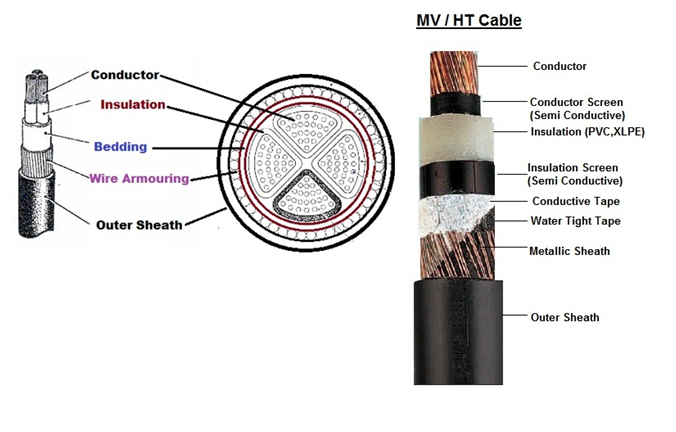
  1. Conductor (For LV/MV/HT Cables) 2. Conductor Screen (For MV/HT Cables) 3. Filler & Binding Tapes (For LV/MV/HT Cables) 4. Insulation (For LV/MV/HT Cables) 5. Insulation Screen (For MV/HT Cables) 6. Separation Tape (For MV/HT Cables) 7. Bedding (Inner Sheath) 8. Metallic Sheen (For MV/HT Cables) 9. Armor (For LV/MV/HT Cables) 10. Outer Sheath (For LV/MV/HT Cables) 11. Water Blocking Tapes –Optional (For MV/HT Cables) 12. Insulation Tapes–Optional (For MV/HT Cables)

Untitled

(1) CONDUCTORS:

  • Code: IS:8130 / IEC 60228/ BS 6360 * Material: Class 2 – Annealed Plain / Tinned Copper / Aluminum. * Used for : LV ,MV & HV Cables * Purpose: * Usually stranded copper (Cu) or aluminum (Al) is used. * Copper is denser and heavier, but more conductive than aluminum. * Electrically equivalent aluminum conductors have a cross-sectional area approximately 1.6 times larger than copper, but half the weight. * The size of the copper / Aluminum conductor forming one of the cores of a cable is expressed in square millimeters (mm2), and the current rating of the cable is dependent upon the cross-sectional area of each core. * Multi core Aluminum or copper conductor are produced by two Shapes * Circular Conductor: multi layers of stranded wires are assembled together to make circular shape. * To achieve a circular conductor, the number of strands follows a particular progression: 3, 7, 19, 37, 61, and 127 etc, the diameter of each strand being chosen to achieve the desired cross-sectional area of whole conductor. * Circular Shape conductor is normally available used up to 200mm2 * Segment Conductor: Five segments of compacted conductor in triangle shape of 72 degree are assembled together with separation of non metallic tapes to reduce the skin effect which reduce the AC conductor resistance. * Larger sizes have conductors with the strands laid up in a segmental formation; this Cables achieves a better space factor and reduces the overall diameter of the cable. It also reduces the inductance of the cable due to decreased spacing between phases * Segmental conductor is normally available from 1000 mm2 and above

 (2) CONDUCTOR SCREEN (SEMI CONDUCTOR SCREEN):

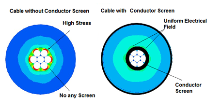
  • Code: IS:7098/IEC:60502/ BS:6622/BS:7835 * Material: Extruded thermo set semi-conducting compound, Carbon paper and carbon loaded polymer. * Used for : Cable from 6 to 30kV (MV & HV Cables) * Purpose: * This screen consists of a lapped copper tape or metallic foil usually less than 1.0mm in thickness, which is the interface between the conductor and the insulation (PVC, XLPE). * The Main Purpose of Conductor Screen is to maintain a uniformly divergent electric field, and to contain the electric field within the cable core. * Conductor Screen is semi-conducting material because Semi-conducting materials do not conduct electricity well enough to be a conductor but will not hold back voltage. It “smoothes” out the surface irregularities of the conductor. The conductor shield makes the voltage on the inside of the insulation the same * Semiconducting screening materials are based on carbon black that is dispersed within a polymer matrix. The concentration of carbon black needs to be sufficiently high to ensure an adequate and consistent conductivity. * The incorporation must be optimized to provide a smooth interface between the conducting and insulating portions of the cable. * The smooth surface is important as it decreases the occurrence of regions of high electrical stress. * Control Electrical Field: Conductor Screen is control the electric field within the insulation and thus the same voltage gradient across it. It also avoids any interaction of the electric stresses due to the voltages on different phase conductors within the same cable. * Reduce Voltage Stress Conductor Screen helps to reduce voltage stress at the interface between the conducting and insulating components. * A typical construction for a medium voltage cable consists of an aluminum conductor covered by a screening layer, then by a polyethylene or ethylene propylene rubber insulation followed by a further screening layer. The coefficient of expansion of the insulation layer is typically ten times greater than that of the aluminum and when the cable is at its maximum operating temperature of 90ºC, a large enough gap can formed to allow electrical discharges to occur. The semi-conducting layer then serves to even out the stresses associated with these discharges, which would otherwise attack the insulation at specific points.

e

  • Uniform Electrical Field: A Black semi-conducting tape is used to maintain a uniform electric field and minimize electrostatic stresses in MV…

Cable Tray Size as per National Electrical Code-2002. Article 392

CABLE TRAY SIZE AS PER NATIONAL ELECTRICAL CODE-2002. ARTICLE 392

(I) NO OF MULTI CORE CABLES LESS THAN 2000 VOLTS IN THE CABLE TRAY

 (A) 4/0 AWG/Kcmill (120 Sq.mm) Cable or Larger Cables:

  • The ladder cable tray: Tray must have an inside available width equal to or greater than the sum of the diameters of the cables, which installed in a single layer. * Solid bottom cable tray: the sum of the cable diameters is not to exceed 90% of the available cable tray width.

 (B) Cables Smaller Than 4/0 AWG/Kcmill (120 Sq.mm)

  • Ladder Type Cable Tray: The total sum of the cross-sectional areas of all the cables to be installed in the cable tray must be equal to or less than the allowable cable area for the tray width, as per following Table. * Solid Bottom Cable Tray: The allowable cable area is reduced by 22%.

Inside width of Cable Tray Allowable Cable Area Sq.inch (Sq.mm) 6 inch (152.5mm) 7 Sq.inch (4516 Sq.mm) 9 inch (228.6mm) 10 Sq.inch (6451 Sq.mm) 12 inch (304.8mm) 14 Sq.inch (9032 Sq.mm) 18 inch (457.2mm) 21 Sq.inch (13548 Sq.mm) 24 inch (609.6mm) 28Sq.inch (18064 Sq.mm)

(C) 4/0 AWG (120 Sq.mm) or Larger Cables Installed with Cables Smaller than 4/0 AWG (120 Sq.mm)

  • Ladder Type Cable Tray: The ladder cable tray needs to be divided into two zones (a barrier or divider is not required but one can be used if desired) so that the No. 4/0 and larger cables have a dedicated zone, as they are to be placed in a single layer. * A direct method to determine the correct cable tray width is to figure the cable tray widths required for each of the cable combinations per steps (2) & (3). Then add the widths in order to select the proper cable tray width.

(D) Multi conductor Control and Signal Cables Only

  • Ladder Type Cable Tray: A ladder cable tray containing only control and/or signal cables may have 50% of its total available cable area filled with cable. * Solid Bottom Cable Tray: When using solid bottom cable tray, the allowable cable area is reduced from 50% to 40%.

(II) NO OF SINGLE CONDUCTOR CABLES < 2000 VOLTS IN THE CABLE TRAY (NEC-392.12)

  • All single conductor cables to be installed in the cable tray must be larger than 1/0 AWG (53.5 Sq.mm) and not to be installed with Solid Cable Tray.

 (A) 1000 Kcmill (500 Sq.mm) or Larger Cables

  • The sum of the diameters (Sd) for all single conductor cables to be installed shall not exceed the cable tray width as per following Table.

Inside width of Cable Tray Allowable Cable Area Sq.inch (Sq.mm) 6 inch (152.5mm) 6.5Sq.inch (4194 Sq.mm) 9 inch (228.6mm) 9.5 Sq.inch (6129 Sq.mm) 12 inch (304.8mm) 13 Sq.inch (8387 Sq.mm) 18 inch (457.2mm) 19 Sq.inch (12258 Sq.mm) 24 inch (609.6mm) 26Sq.inch (16774 Sq.mm) 30 inch (762mm) 32.5Sq.inch (20968 Sq.mm) 36 inch (914.5mm) 39Sq.inch (25161Sq.mm)

(2) 250 Kcmil (120 Sq.mm) to 1000 Kcmil (500 Sq.mm) Cables

  • The total sum of the cross-sectional areas of all the single conductor cables to be installed in the cable tray must be equal to or less than the allowable cable area for the tray width, as given in following Table

Inside width of Cable Tray Allowable Cable Area Sq.inch (Sq.mm) 6 inch (152.5mm) 6.5Sq.inch (4194 Sq.mm) 9 inch (228.6mm) 9.5 Sq.inch (6129 Sq.mm) 12 inch (304.8mm) 13 Sq.inch (8387 Sq.mm) 18 inch (457.2mm) 19 Sq.inch (12258 Sq.mm) 24 inch (609.6mm) 26Sq.inch (16774 Sq.mm) 30 inch (762mm) 32.5Sq.inch (20968 Sq.mm) 36 inch (914.5mm) 39Sq.inch (25161Sq.mm)

(3) 1000 Kcmil (500 Sq.mm) or Larger Cables Installed with Cables Smaller Than 1000 Kcmil (500 Sq.mm)

  • The total sum of the cross-sectional areas of all the single conductor cables to be installed in the cable tray must be equal to or less than the allowable cable area for the tray width, as given in following Table

Inside width of Cable Tray Allowable Cable Area Sq.inch (Sq.mm) 6 inch (152.5mm) 6.5Sq.inch (4194 Sq.mm) 9 inch (228.6mm) 9.5 Sq.inch (6129 Sq.mm) 12 inch (304.8mm) 13 Sq.inch (8387 Sq.mm) 18 inch (457.2mm) 19 Sq.inch (12258 Sq.mm) 24 inch (609.6mm) 26Sq.inch (16774 Sq.mm) 30 inch (762mm) 32.5Sq.inch (20968 Sq.mm) 36 inch (914.5mm) 39Sq.inch (25161Sq.mm)

(4) Single Conductor Cables 1/0 (50Sq.mm) to 4/0 (120Sq.mm)

  • These single conductors must be installed in a single layer. * Note: It is the opinion of some that this practice may cause problems with * To avoid these potential problems due to unbalanced voltages, the individual conductors for this type of cable tray wiring system should be bundled with ties. The bundle should contain all of the three phase conductors with the neutral if used.

Single conductor Size Cable Tray width 152mm 228mm 304mm 457mm 609mm 1/0AWG (50Sq.mm) 10 15 20 31 2/0AWG (70Sq.mm) 9 14 19 29 3/0AWG (9550Sq.mm) 8 13 17 26 4/0AWG (120Sq.mm) 8 12 16 250kcmill (120Sq.mm) 11 18 24 350kcmill (185Sq.mm) 9 14 19 500kcmill (240Sq.mm) 7 11 14 750kcmill (400Sq.mm) 5 8 10 1000kcmill (500Sq.mm) 4 6 8

(III) NO OF CABLE…

Difference between Unearthed Cable & Earthed Cables

DIFFERENCE BETWEEN UNEARTHED CABLE & EARTHED CABLES

INTRODUCTION:

  • In HT electrical distribution, the system can be earthed or unearthed. The selection of earthed/unearthed cable will depend on system. If distribution system is earthed then we have to use cable which is manufactured for earthed system. (Which the manufacturer specifies). If the system is unearthed then we need to use cable which is manufactured for unearthed system. The unearthed system requires high insulation level compared to earthed System. * For earthed and unearthed XLPE cables, the IS 7098 part2 1985 does not give any difference in specification. The insulation level for cable for unearthed system has to be more.

EARTHED SYSTEM:

  • Earlier the generators and transformers were of small capacities and hence the fault current was less. The star point was solidly grounded. This is called earthed system. * In Three phases earthed system, phase to earth voltage is 1.732 times less than phase to phase voltage. Therefore voltage stress on cable to armor is 1.732 times less than voltage stress between conductors to conductor. * Where in unearthed system, (if system neutral is not grounded) phase to ground voltage can be equal to phase to phase voltage. In such case the insulation level of conductor to armor should be equal to insulation level of conductor to conductor. * In an earthed cable, the three phase of cable are earthed to a ground. Each of the phases of system is grounded to earth. Examples: 1.9/3.3 KV, 3.8/6.6 KV system

 UNEARTHED SYSTEM:

  • Today generators of 500MVA capacities are used and therefore the fault level has increased. In case of an earth fault, heavy current flows into the fault and this lead to damage of generators and transformers. To reduce the fault current, the star point is connected to earth through a resistance. If an earth fault occurs on one phase, the voltage of the faulty phase with respect to earth appears across the resistance. Therefore, the voltage of the other two healthy phases with respect to earth rises by 1.7 times. If the insulation of these phases is not designed for these increased voltages, they may develop earth fault. This is called unearthed system. * In an unearth system, the phases are not grounded to earth .As a result of which there are chances of getting shock by personnel who are operating it. Examples : 6.6/6.6 KV, 3.3/3.3 KV system. * Unearthed cable has more insulation strength as compared to earthed cable. When fault occur phase to ground voltage is √3 time the normal phase to ground voltage. So if we used earthed cable in unearthed System, It may be chances of insulation puncture. So unearthed cable are used. Such type of cable is used in 6.6 KV systems where resistance type earthing is used.

 NOMENCLATURE:

  • In simple logic the 11 KV earthed cable is suitable for use in 6.6 KV unearthed system. The process of manufacture of cable is same. The size of cable will depend on current rating and voltage level. * Voltage Grade (Uo/U) where Uo is Phase to Earth Voltage & U is Phase to Phase Voltage. * Earthed system has insulation grade of KV / 1.75 x KV. * For Earthed System (Uo/U): 1.9/3.3 kV, 3.8/6.6 kV, 6.35/11 kV, 12.7/22 kV and 19/33 kV. * Unearthed system has insulation grade of KV / KV. * For Unearthed System (Uo/U): 3.3/3.3 kV and 11/11 kV. * 3 phase 3 wire system has normally Unearthed grade cables and 3 phase 4 wire systems can be used earthed grade cables, insulation used is less, and cost is less.

THUMB RULE:

  • As a thumb rule we can say that 6.6KV unearthed cable is equal to 11k earthed cable i.e. 6.6/6.6kv Unearthed cable can be used for 6.6/11kv earthed system. because each core of cable have the insulation level to withstand 6.6kv so between core to core insulation level will be 6.6kv+6.6kv = 11kv * For transmission of HT, earthed cable will be more economical due to low cost where as unearthed cables are not economical but insulation will be good. * Generally 6.6 kV and 11kV systems are earthed through a neutral grounding resistor and the shield and armor are also earthed, especially in industrial power distribution applications. Such a case is similar to an unearthed application but with earthed shield (some times called solid bonding). In such cases, unearthed cables may be used so that the core insulation will have enough strength but current rating is de-rated to the value of earthed cables. But it is always better to mention the type of system earthing in the cable specification when ordering the cables so that the cable manufacturer will take care of insulation strength and de rating.

Type of Gland

TYPE OF GLAND

CABLE GLANDS

  • A device designed to permit the entry of cable in to electrical equipment which provide sealing ,retention and earthing, bonding, grounding, insulation, strain relief or combination of all these. * Gland should maintain overall integrity of enclosure in to which it is to be fitted.

GLAND SELECTION

  • Gland should be selected on following Points
  1. Type of Cable 2. Gland Size 3. Entry Type/Thread Specification of application 4. Ingress Protection required. 5. Material
  • Type of Cable:

  • Unarmored: Unarmored Cable will require outer seal within Gland to not only Provide ingress protection but also degree of retention. * Armored: Gland that required clamping mechanism to terminate the armored both mechanically and electrically. * The Gland will usually be required to provide ingress protection by sealing outer sheath and retention by clamping amour.

TYPE OF GLANDS:

  1. Brass Indoor Type Gland 2. Brass Outdoor Type Gland 3. Brass Straitening Unarmored Cable Gland 4. Brass Weather Proof Gland 5. PG Threaded Gland: 6. Industrial Type Gland
  1. BRASS INDOOR TYPE GLAND
  • This Gland is quite handy in use with various types of cable whether plastic, rubberized, metal or any other. * Application: Dry indoor, for use with all type of SWA cables, plastic or rubber sheathed cable. * Brass indoor gland suitable for single wire armored, plastic or rubber sheathed cable. Recommended to use with shroud for additional ingress protection.

  • Cable Type: Steel Wire Amour. * Amour Clamping: Two Part Amour Lock.

  1. BRASS OUTDOOR TYPE GLAND
  • This come in stunning high quality material for use in outdoor or indoor application with various types of cables sheathed or unsheathed. * Brass indoor and outdoor gland popularly used with single wire armored. * Plastic or rubber sheathed cable. Terminates and secure cable armoring and outer seal grips sheath of cable thus ensuring mechanical strength and earth continuity. * CW brass glands are also supplied with integral earth facilities. * Recommended to use PVC shroud for additional ingress protection

  • Application: 

  • a) Outdoor or indoor, for use with all type of SWA cables, plastic or rubber sheathed cable. * b) Most suitable for SWA, plastic of rubber (Elastomeric) sheathed cables. * c) Used in dry indoor conditions. * d) No loose parts and easy to install. * e) Save times & money.

  • Gland size: 20 mm to 75 mm (S & L) * Accessories :Earth Tag, PVC Shroud, Neo prime Rubber & LSF Rubber, PVC Washer, Brass Lock Nut. * Cable Type: Wire Braid Armor. * Armor Clamping: Three Parts (With Lock Nut).

(3) BRASS STRAITENING UNARMORED CABLE GLAND

  • Nickel plated or natural brass A2 type cable glands are used with variety of unarmored or rubber sheathed cables. * Brass indoor and outdoor cable gland suitable for all types of unarmored cables, plastic or rubber sheathed cables.


  • Application:
  1. For use with unarmored elastomeric and plastic insulated cables. 2. Indoor & Outdoor whenever it is required to provide sealing on cable outer sheath.
  • Size : Metric – 20mm to 75mm (S/L) * Accessories: Earth Tag, PVC Shroud, Neo prime Rubber & LSF Rubber, PVC Washer, Brass Lock Nut. * Cable Type : Unarmored
  1. BRASS WEATHER PROOF GLAND
  • Unlike other types of cable glands, This type cable gland is used precisely with single armored various types of swa cables whether plastic or rubber sheathed ones. this type cable gland is known for its uninterrupted services once the gland is fixed to the desired wires and wire components. * Suitable for SWA or rubber sheathed cables. * Outer seal grips bedding layer of cable for use in most climatic conditions. * Weather proof and water proof. * Design has separate armor lock rings. Can be supplied with integral earth facility. * Gland size: 20 mm to 75 mm (S & L)

  • Application :

  1. Outdoor or indoor, for use with single armored, all type of SWA cable, plastic or rubber sheathed cable. 2. E1W Gland is Weatherproof & Waterproof Cable Gland
  • Cable Type : Steel Wire Armour * Armour Clamping: Three Part Armour Lock * Sealing Technique: Compression & Displacement Type * Sealing Area(s): Inner & Outer Sheath
  1. PG THREADED GLAND:
  • Nickel chrome plated PG threaded cable gland is a custom made threaded gland to meet the needs from the meet industries. Apart from the round headed PG threaded cable gland, we also offer hexagonal gland or any other like spherical rectangular or any other dimensional PG threaded cable gland as per the specification of the customer.


EHV XLPE – Current Rating

EHV XLPE – CURRENT RATING

EHV XLPE CABLE:

3.8 / 6.6 KV(6.6 KV Earthed) Single Core AL/COPPER COND, XLPE INSULATED CABLES As per IS:7098 (Part-II)

Cross-sectional area (Sq MM)

ARMOURED CABLE

Overall Diameter (mm)

Normal Current Rating in Amps 

Short Circuit Current Rating for 1Sec.duration in K. Amps 

Aluminum Conductor

Copper Conductor

Aluminum

Copper

Ground Duct Air Ground Duct Air 1cX25 23 100 90 120 130 115 155 2.35 3.58 1cX 35 24 120 105 145 155 140 185 3.29 5.00 1cX50 25 140 125 170 185 160 220 4.70 7.15 1cX70 27 175 155 215 225 195 275 6.58 10.01 1cX 95 28 205 180 260 265 235 340 8.93 13.59 1cX120 30 235 205 305 300 265 390 11.28 17.16 1cX150 32 260 230 345 335 295 440 14.10 21.45 1cX185 34 295 260 395 380 330 510 17.39 26.46 1cX240 37 340 300 470 435 380 600 22.56 34.32 1cX300 39 385 335 540 490 425 680 28.20 42.90 1cX400 44 0.57 440 380 630 550 480 790 37.60 1cX 500 47 0.60 495 430 730 610 530 910 47.00 1cX 630 51 0.67 560 480 840 680 580 1030 59.22 1cX800 57 0.76 620 530 960 740 630 1140 75.20 1cX1000 61 0.82 680 580 1070 790 670 1250 94.00

3.8 / 6.6 KV(6.6 KV Earthed) Three Core AL/COPPER COND, XLPE INSULATED CABLES As per IS:7098 (Part-II)

Cross-sectional area (Sq MM)

ARMOURED CABLE

Overall Diameter (mm)

Normal Current Rating in Amps 

Short Circuit Current Rating for 1Sec.duration in K. Amps 

Aluminum Conductor

Copper Conductor

Aluminum

Copper

Ground Duct Air Ground Duct Air 3cX 25 40 95 82 105 120 105 135 2.35 3.58 3cX 35 42 115 97 125 145 125 165 3.29 5.01 3cX 50 45 130 115 150 170 150 195 4.70 7.15 3cX 70 49 160 140 190 210 180 240 6.58 10.01 3cX 95 54 190 165 230 250 215 295 8.93 13.59 3cX 120 58 220 190 260 280 240 335 11.28 17.16 3cX 150 61 245 210 295 310 270 380 14.10 21.45 3cX 185 65 275 240 335 350 305 430 17.39 26.46 3cX 240 72 315 275 395 400 350 500 22.56 34.32 3cX 300 77 355 310 450 445 390 570 28.20 42.90 3cX 400 88 400 350 520 500 440 650 37.60 57.20

6.6 / 11 KV (6.6KV Un-Earthed/ 11 KV Earthed) Single Core AL/COPPER COND, XLPE INSULATED, CABLES As per IS:7098 (Part-II)

Cross-sectional area (Sq MM)

ARMOURED CABLE

Overall Diameter (mm)

Normal Current Rating in Amps 

Short Circuit Current Rating for 1Sec.duration in K. Amps 

Aluminum Conductor

Copper Conductor

Aluminum

Copper

Ground Duct Air Ground Duct Air 1cX25 24 100 90 120 130 115 155 2.35 3.58 1cX 35 25 120 105 145 155 140 185 3.29 5.00 1cX50 26 140 125 170 185 160 220 4.70 7.15 1cX70 28 175 155 215 225 195 275 6.58 10.01 1cX 95 30 205 180 260 265 235 340 8.93 13.59 1cX120 32 235 205 305 300 265 390 11.28 17.16 1cX150 33 260 230 345 335 295 440 14.10 21.45 1cX185 36 295 260 395 380 330 510 17.39 26.46 1cX240 39 340 300 470 435 380 600 22.56 34.32 1cX300 41 385 335 540 490 425 680 28.20 42.90 1cX400 44 440 380 630 550 480 790 37.60 57.20 1cX 500 47 495 430 730 610 530 910 47.00 71.50 1cX 630 51 560 480 840 680 580 1030 59.22 90.10 1cX800 57 620 530 960 740 630 1140 75.20 114.40 1cX1000 61 680 580 1070 790 670 1250 94.00 143.00

6.6 / 11 KV (6.6KV Un-Earthed/ 11 KV Earthed) Three Core AL/COPPER COND, XLPE INSULATED, CABLES As per IS:7098 (Part-II)

Cross-sectional area (Sq MM)

ARMOURED CABLE

Overall Diameter (mm)

Normal Current Rating in Amps 

Short Circuit Current Rating for 1Sec.duration in K. Amps 

Aluminum Conductor

Copper Conductor

Aluminum

Copper

Ground Duct Air Ground Duct Air 3cX 25 43 95 82 105 120 105 135 2.35 3.58 3cX 35 46 115 97 125 145 125 165 3.29 5.01 3cX 50 50 130 115 150 170 150 195 4.70 7.15 3cX 70 54 160 140 190 210 180 240 6.58 10.01 3cX 95 58 190 165 230 250 215 295 8.93 13.59 3cX 120 62 220 190 260 280 240 335 11.28 17.16 3cX 150 65 245 210 295 310 270 380 14.10 21.45 3cX 185 70 275 240 335 350 305 430 17.39 26.46 3cX 240 76 315 275 395 400 350 500 22.56 34.32 3cX 300 80 355 310 450 445 390 570 28.20 42.90 3cX 400 90 400 350 520 500 440 650 37.60 57.20

11 KV(11 KV Un-Earthed) Single Core AL/COPPER COND., XLPE INSULATED CABLES As per IS:7098 (Part-II)

Cross-sectional area (Sq MM)

ARMOURED CABLE

Overall Diameter (mm)

Normal Current Rating in Amps 

Short Circuit Current Rating for 1Sec.duration in K. Amps 

Aluminum Conductor

Copper Conductor

Aluminum

Copper

Ground Duct Air Ground Duct Air 1cX25 28 100 90 120 130 115 155 2.35 3.58 1cX 35 29 120 105 145 155 140 185 3.29 5.00 1cX50 31 140 125 170 185 160 220 4.70 7.15 1cX70 33 175 155 215 225 195 275 6.58 10.01 1cX 95 34 205 180 260 265 235 340 8.93 13.59 1cX120 37 235 205 305 300 265 390 11.28 17.16 1cX150 38 260 230 345 335 295 440 14.10 21.45 1cX185 40 295 260 395 380 330 510 17.39 26.46 1cX240 43 340 300 470 435 380 600 22.56 34.32 1cX300 44 385 335 540 490 425 680 28.20 42.90 1cX400 48 440 380 630 550 480 790 37.60 57.20 1cX 500 53 495 430 730 610 530 910 47.00 71.50 1cX 630 56 560 480 840 680 580 1030 59.22 90.10 1cX800 61 620 530 960 740 630 1140 75.20 114.40 1cX1000 65 680 580 1070 790 670 1250…

XLPE Cable-Current Rating

XLPE CABLE-CURRENT RATING

XLPE INSULATED ARMORED & UNARMORED CABLES:

1.1 KV SINGLE CORE AL/COPPER COND,XLPE INSULATED CABLES As per IS:7098 (Part-I)

Cross-sectional area (Sq MM)

UN-ARMOURED CABLE

Overall Diameter (mm)

Normal Current Rating in Amps

Short Circuit Current Rating for 1Sec.duration in K. Amps

Aluminums Conductor

Copper Conductor

Aluminums

Copper

Ground Duct Air Ground Duct Air 1cX4

8

 — — — 48 47 45 0.376 0.572 1cX 6 9 48 45 45 60 59 57 0.564 0.858 1cX10 10 62 62 61 80 78 77 0.940 1.430 1cX16 11 81 80 83 104 102 106 1.504 2.288 1cX25 12 99 90 115 130 115 145 2.350 3.575 1cX 35 13 117 110 135 155 140 175 3.290 5.005 1cX50 15 138 125 170 185 165 215 4.700 7.150 1cX70 16 168 155 210 225 200 270 6.580 10.01 1cX 95 18 204 185 255 265 235 330 8.930 13.59 1cX120 20 230 210 300 300 265 380 11.28 17.16 1cX150 22 265 230 342 335 300 430 14.10 21.45 1cX185 24 295 260 385 380 335 495 17.39 26.46 1cX240 27 340 300 450 435 385 590 22.56 34.32 1cX300 30 390 335 519 490 430 670 28.20 42.90 1cX400 33 450 380 605 550 480 780 37.60 57.20 1cX 500 36 500 430 700 610 530 900 47.00 71.50 1cX 630 40 555 485 809 680 590 1020 59.22 90.09 1cX800 47 625 530 935 740 630 1140 75.20 114.40 1cX1000 51 690 570 1065 780 660 1250 94.00 143.00

1.1 KV SINGLE CORE AL/COPPER COND,XLPE INSULATED CABLES As per IS:7098 (Part-I)

Cross-sectional area (Sq MM)

ARMOURED CABLE

Overall Diameter (mm)

Normal Current Rating in Amps

Short Circuit Current Rating for 1Sec.duration in K. Amps

Aluminums Conductor

Copper Conductor

Aluminums

Copper

Ground Duct Air Ground Duct Air 1cX4 10 — — — 48 47 45 0.376 0.572 1cX 6 11 45 45 40 60 59 57 0.56 0.858 1cX10 12 59 62 53 80 78 77 0.94 1.43 1cX16 13 76 80 73 104 102 106 1.50 2.29 1cX25 14 99 90 115 130 115 145 2.35 3.58 1cX 35 15 117 110 140 155 140 175 3.29 5.01 1cX50 17 138 125 170 185 165 215 4.70 7.15 1cX70 19 168 155 210 225 200 270 6.58 10.01 1cX 95 22 204 185 255 265 235 330 8.93 13.59 1cX120 24 230 210 300 300 265 380 11.28 17.16 1cX150 25 265 230 342 335 300 430 14.10 21.45 1cX185 28 295 260 385 380 335 495 17.39 26.46 1cX240 30 340 300 450 435 385 590 22.56 34.32 1cX300 33 390 335 519 490 430 670 28.20 42.90 1cX400 38 450 380 605 550 480 780 37.60 57.20 1cX 500 41 500 430 700 610 530 900 47.00 71.50 1cX 630 46 555 485 809 680 590 1020 59.22 90.09 1cX800 51 625 530 935 740 630 1140 75.20 114.40 1cX1000 56 690 570 1065 780 660 1250 94.00 143.00

1.1 KV Two CORE AL/COPPER COND,XLPE INSULATED As per IS:7098(Part-I)

Cross-sectional area (Sq MM)

UN-ARMOURED CABLE

Overall Diameter (mm)

Normal Current Rating in Amps

Short Circuit Current Rating for 1Sec.duration in K. Amps

Aluminums Conductor

Copper Conductor

Aluminums

Copper

Ground Duct Air Ground Duct Air 2cX4 13 34 28 30 44 37 39 0.376 0.572 2cX 6 14 43 37 40 55 47 50 0.564 0.858 2cX10 17 57 48 53 74 61 67 0.940 1.430 2cX16 17 78 61 70 94 78 85 1.50 2.29 2cX25 19 95 80 99 120 100 125 2.35 3.58 2cX35 20 116 94 117 145 120 155 3.29 5.01 2cX50 22 140 110 140 170 145 190 4.70 7.15 2cX70 25 170 140 176 210 175 235 6.58 10.01 2cX95 28 200 165 221 250 210 290 8.93 13.59 2cX120 31 225 185 258 285 240 330 11.28 17.16 2cX150 33 255 210 294 315 270 375 14.10 21.45 2cX185 37 285 235 339 355 300 435 17.39 26.46 2cX240 41 325 270 402 410 350 510 22.56 34.32 2cX300 44 370 305 461 460 390 590 28.20 42.90 2cX400 48 435 350 542 520 440 670 37.60 57.20 2cX500 54 481 405 624 580 480 750 47.00 71.50 2cX630 62 537 470 723 680 575 875 59.22 90.09

1.1 KV Two CORE AL/COPPER COND,XLPE INSULATED As per IS:7098(Part-I)

Cross-sectional area (Sq MM)

ARMOURED CABLE

Overall Diameter (mm)

Normal Current Rating in Amps

Short Circuit Current Rating for 1Sec.duration in K. Amps

Aluminums Conductor

Copper Conductor

Aluminums

Copper

Ground Duct Air Ground Duct Air 2cX4 15 34 28 30 44 37 39 0.376 0.572 2cX 6 16 43 37 40 55 47 50 0.564 0.858 2cX10 18 57 48 53 74 61 67 0.940 1.430 2cX16 19 78 61 70 94 78 85 1.50 2.29 2cX25 21 95 80 99 120 100 125 2.35 3.58 2cX35 23 116 94 117 145 120 155 3.29 5.01 2cX50 25 140 110 140 170 145 190 4.70 7.15 2cX70 28 170 140 176 210 175 235 6.58 10.1 2cX95 31 200 165 221 250 210 290 8.93 13.59 2cX120 34 225 185 258 285 240 330 11.28 17.16 2cX150 37 255 210 294 315 270 375 14.10 21.45 2cX185 40 285 235 339 355 300 435 17.39 26.46 2cX240 45 325 270 402 410 350 510 22.56 34.32 2cX300 49 370 305 461 460 390 590 28.20 42.90 2cX400 52 0.33 435 350 542 520 440 670 37.60 2cX500 60 0.34 481 405 624 580 480 750 47.00 2cX630 66 0.36 537 470 723 680 575 875 59.22

1.1 KV Three CORE AL/COPPER COND,XLPE INSULATED As per IS:7098(Part-I)

Cross-sectional area (Sq MM)

UN-ARMOURED CABLE

Overall Diameter (mm)

Normal Current Rating in Amps

Short Circuit Current Rating for 1Sec.duration in K. Amps

Aluminums Conductor

Copper Conductor

Aluminums

Copper

Ground Duct Air Ground Duct Air 3cX 4 14 34 28 30 44 37 39 0.376 0.572 3cX…