Site logo
Electrical Engineering Academy

PVC Cable-Current Rating

PCV CABLE-CURRENT RATING

FLEXIBLE PVC INSULATED CABLE

PVC- Insulated 1 core unsheathed / Sheathed flexible cord with copper conductor 1.1KV ( As per IS:694 – 1990 )

Nominal Conductor Area (Sq.mm)

UN SHEATHED

SHEATHED

Maximum Conductor Resistance at 20°C (ohm/km)

Current Carrying Capacity (Amp)

Nominal Thickness of Insulation (mm)

Maximum overall Diameter (mm)

Approx. Weight (kg/100m)

Nominal Thickness of Insulation (mm)

Nominal Thickness of Sheath (mm)

Maximum Overall Diameter (mm)

Approx. Weight (kg/100m)

1cX0.5

0.6

2.3

0.9

0.6

0.9

4.5

2.6

39

4

1cX0.75

0.6

2.5

1.2

0.6

0.9

4.7

3

26

7

1cX1

0.6

2.7

1.5

0.6

0.9

4.9

3.4

19.5

11

1cX1.5

0.6

3

2

0.6

0.9

5.4

4.3

13.3

15

1cX2.5

0.7

3.7

3.2

0.7

1

6.2

6

7.98

19

1cX4

0.8

4.4

4.9

0.8

1

7

8.2

4.95

26

1cX6

0.8

5

7

0.8

1

7.4

10.3

3.3

35

1cX10

1

7

11.9

1

1

7.7

13

1.91

46

1cX16

1

9

20.1

1

1

9.8

21.8

1.21

62

1cX25

1.2

10

27.4

1.2

1.1

12

32.1

0.78

80

1cX35

1.2

11.4

36.7

1.2

1.1

13

42.7

0.554

102

1cX50

1.4

13.5

52.5

1.4

1.2

15

59.7

0.386

138

1cX70

1.4

16

72.3

1.4

1.2

17.8

80.6

0.272

214

1cX95

1.6

18

96.1

1.6

1.4

20.7

108.1

0.206

254

1cX120

1.6

20.5

120.3

1.6

1.4

22.2

132.5

0.161

300

PVC- Insulated and PVC – Sheathed 2 core flexible cord with copper conductor 1.1KV ( As per IS:694 – 1990 )

Nominal Conductor Area (Sq.mm)

Nominal Thickness of Insulation (mm)

Nominal Thickness of Sheath (mm)

2 CORE CIRCULAR

2 CORE FLAT

Maximum Conductor Resistance at 20°C (ohm/km)

Current Carrying Capacity (Amp)

Maximum overall Diameter (mm)

Approx. Weight (kg/100m)

Maximum overall Diameter (mm)

Approx. Weight (kg/100m)

2cX0.5

0.6

0.9

7.2

5.5

4.9×7.2

4.7

39

4

2cX0.75

0.6

0.9

7.8

6.5

5.2×7.8

5.5

26

7

2cX1

0.6

0.9

8

7.5

5.4×8.0

6.3

19.5

11

2cX1.5

0.6

0.9

8.6

9.2

5.6×8.6

8

13.3

15

2cX2.5

0.7

1

10.5

13.5

6.6×10.5

11.2

7.98

19

2cX4

0.8

1

12

19

7.2×12.0

15.8

4.95

26

PVC- Insulated and PVC – Sheathed 3 core flexible cord with copper conductor 1.1KV ( As per IS:694 – 1990 )

Nominal Conductor Area (Sq.mm)

Nominal Thickness of Insulation (mm)

Nominal Thickness of Sheath (mm)

3 CORE CIRCULAR

3 CORE FLAT

Maximum Conductor Resistance at 20°C (ohm/km)

Current Carrying Capacity (Amp)

Maximum overall Diameter (mm)

Approx. Weight (kg/100m)

Maximum overall Diameter (mm)

Approx. Weight (kg/100m)

3cX0.5

0.6

0.9

7.6

6.4

0.9

5.1

39

4

3cX0.75

0.6

0.9

8.2

7.6

0.9

6.1

26

7

3cX1

0.6

0.9

9.2

10.9

0.9

7.1

19.5

11

3cX1.5

0.6

0.9

9.2

10.9

0.9

8.7

13.3

15

3cX2.5

0.7

1

11

16.2

1

13

7.98

19

3cX4

0.8

1

12.5

23.7

1

18.6

4.95

26

 PVC INSULATED ARMORED & UNARMORED CABLES:

1.1 KV SINGLE CORE AL/COPPER COND., PVC INSULATED CABLES As per IS:1554 (Part-I)

Cross-sectional area (Sq MM)

UN-ARMOURED CABLE

Overall Diameter (mm)

Normal Current Rating in Amps

Short Circuit Current Rating for 1Sec.duration in K. Amps

Aluminums Conductor

Copper Conductor

Aluminum

Copper

Ground Duct Air Ground Duct Air 1cX4 8 — — — 39 38 35 0.304 0.460 1cX 6 9 39 37 35 49 48 44 0.456 0.690 1cX10 10 51 51 47 65 64 60 0.760 1.150 1cX16 11 66 65 64 85 83 82 1.220 1.84 1cX25 13 86 84 84 110 110 110 1.900 2.88 1cX 35 14 100 100 105 130 125 130 2.660 4.03 1cX50 16 120 115 130 155 150 165 3.800 5.75 1cX70 17 140 135 155 190 175 205 5.320 8.05 1cX 95 19 175 155 190 220 200 245 7.220 10.90 1cX120 21 195 170 220 250 220 280 9.120 13.80 1cX150 23 220 190 250 280 245 320 11.40 17.30 1cX185 25 240 210 290 305 260 370 14.10 21.30 1cX240 28 270 225 335 345 285 425 18.20 27.30 1cX300 30 295 245 380 375 310 475 22.80 34.50 1cX400 35 325 275 435 400 335 550 30.40 46.00 1cX 500 38 345 295 480 425 355 590 38.00 57.50 1cX 630 43 390 320 550 470 375 660 47.90 72.50 1cX800 48 450 380 610 530 425 725 60.80 92.00 1cX1000 52 500 415 680 590 740 870 76.00 115.00

1.1 KV SINGLE CORE AL/COPPER COND., PVC INSULATED CABLES As per IS:1554 (Part-I)

Cross-sectional area (Sq MM)

ARMOURED CABLE

Overall Diameter (mm)

Normal Current Rating in Amps

Short Circuit Current Rating for 1Sec.duration in K. Amps

Aluminums Conductor

Copper Conductor

Aluminums

Copper

Ground Duct Air Ground Duct Air 1cX4 11 31 30 27 39 38 35 0.304 0.460 1cX 6 12 39 37 35 49 48 44 0.456 0.690 1cX10 13 51 51 47 65 64 60 0.760 1.150 1cX16 14 66 65 64 85 83 82 1.220 1.840 1cX25 15 86 84 84 110 110 110 1.900 2.880 1cX 35 16 100 100 105 130 125 130 2.660 4.030 1cX50 18 120 115 130 155 150 165 3.800 5.750 1cX70 20 140 135 155 190 175 205 5.320 8.050 1cX 95 22 175 155 190 220 200 245 7.220 10.90 1cX120 24 195 170 220 250 220 280 9.120 13.80 1cX150 26 220 190 250 280 245 320 11.400 17.30 1cX185 29 240 210 290 305 260 370 14.100 21.30 1cX240 32 270 225 335 345 285 425 18.200 27.60 1cX300 33 295 245 380 375 310 475 22.800 34.50 …
E

EHV/HV Cable Sheath Earthing

EHV/HV CABLE SHEATH EARTHING

EHV/HV CABLE SHEATH EARTHING:

 INTRODUCTION:

  • In urban areas, high voltage underground cables are commonly used for the transmission and distribution of electricity. Such high voltage cables have metallic sheaths or screens surrounding the conductors, and/or armour and metallic wires surrounding the cables. During earth faults applied to directly earthed systems, these metallic paths are expected to carry a substantial proportion of the total fault current, which would otherwise flow through the general mass of earth, while returning to system neutrals. These alternative return paths must be considered when determining the extent of the grid potential rise at an electrical plant due to earth faults. * For safety and reliable operation, the shields and metallic sheaths of power cables must be grounded. Without grounding, shields would operate at a potential considerably above ground. Thus, they would be hazardous to touch and would cause rapid degradation of the jacket or other material intervening between shield and ground. This is caused by the capacitive charging current of the cable insulation that is on the order of 1 mA/ft of conductor length. * This current normally flows, at power frequency, between the conductor and the earth electrode of the cable, normally the shield. In addition, the shield or metallic sheath provides a fault return path in the event of insulation failure, permitting rapid operation of the protection devices. * In order to reduce Circulating current and electric potential difference between the sheathings of single core three-phase cables, the sheathing is grounded and bonded at one or both ends of the cables. If the cable is long, double bonding has to be carried out which leads to circulating currents and increased total power loss. Raising the sheath’s resistance, by decreasing its cross section and increasing its resistivity, can reduce this almost to the level of the core losses. * However, in case of an earth fault, a considerable portion of the fault current flows through the increased sheath resistance, creating much higher power in the sheaths than in the faulty core. A simple solution, a conductor rod buried into the soil above or under the cable can divert this power from the sheaths.

CABLE SCREEN:

 (1) PURPOSE OF CABLE SCREEN:

    • Cable screen controls the electric field stress in the cable insulation. * Cable Screen Provides return path for Cable neutral and fault current. * If the screen is earthed at two ends than it provides Shielding for electromagnetic radiation. * Enclosing dangerous high voltage with earth potential for safety.

 (2) PURPOSE OF BONDING CABLE SCREENS AT BOTH ENDS:

  • The electric power losses in a cable circuit are dependent on the currents flowing in the metallic sheaths of the cables so by reducing the current flows in metallic sheath by different methods of bonding we can increases the load current carrying capacity (ampacity) of the cable. * It provides low impedance fault current return path and provides neutral point for the circuit. * It provides shielding of electromagnetic field.

(3) INDUCED VOLTAGE & CIRCULATING CIRCULATING CURRENT IN CABLE SCREEN:

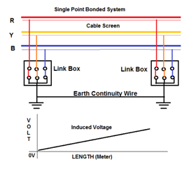
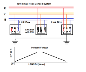
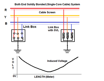
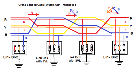
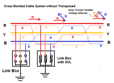
  • Electromagnetic coupling between the core and screen Electromagnetic screen. * If the cable screen is single point bonded, no electrical continuity and mmf generates a voltage. * If the cable screen is bonded at both ends, the mmf will cause circulating current to flow if there is electrical continuity. * The circulating current produces an opposing magnetic field. * Suitable bonding method should be employed to meet the standing voltage limit and keep Circulating current to an acceptable level.

LAYING METHOD OF CABLE:

  • The three Single core cables in a 3-phase circuit can be placed in different formations. Typical formations include trefoil (triangular) and flat formations.

(1) TREFOIL FORMATION:

  • To minimize the electromechanical forces between the cables under short-circuit conditions, and to avoid eddy-current heating in nearby steelwork due to magnetic fields set up by load currents, the three single-core cables comprising the three phases of a 3-phase circuit are always run clamped in ‘Trefoil’ formation. * Advantage:
  1. This type of Formation minimizes the sheath circulating currents induced by the magnetic flux linking the cable conductors and metallic sheath or copper wire screens. 2. This configuration is generally used for cables of lower voltages (33 to 132kV) and of smaller conductor sizes.
  • Disadvantages:
  1. The trefoil formation is not appropriate for heat dissipation because there is an appreciable mutual he…

Low Voltage and High Voltage Cable Testing

LOW VOLTAGE AND HIGH VOLTAGE CABLE TESTING

LOW VOLTAGE AND HIGH VOLTAGE CABLE TESTING

 LOW VOLTAGE XLPE DISTRIBUTION CABLES:

INSULATION RESISTANCE:

  • Cables shall be tested for insulation resistance with an insulation tester (i.e. Megger) at 1000 Volts for 1 minute. * The minimum insulation resistance to earth or between phases shall be 100 meg-ohms. * The instrument used for this measurement shall have a minimum resolution of 10 meg-ohms on the 0 to 500 meg-ohm range. * At the conclusion of LV insulation resistance testing, the neutrals must be connected to the earth stakes.

PHASING TEST:

  • The correct phasing of all LV circuits shall be checked at all positions where the LV cables are terminated into fuse bases and where any LV cable is run from point to point. * This test shall be performed with an instrument designed for the purpose. Mains frequency voltage of 240 Volts is not acceptable for this test. * The neutral conductor shall be connected to the earth stake for this test.

CONTINUITY TEST (RESISTANCE OF BOLTED CONNECTIONS):

  • For loop LV systems, a continuity test shall be carried out on each LV circuit to ensure that all bolted connections are complete and adequate. The test shall be carried out as follows: * (1) At the transformer firmly bond all 4 conductors together * (2) Undertake a continuity test at every point where there is a service provision or open point. In a fused service pillar the bottom row of fuses bases must be the point at which the test is undertaken as that is the furthest extent of the network. * The difference between the readings of each phase conductor and the neutral for each individual test shall not be greater than 10% of each other. Any difference greater than this may indicate a loose or dirty connection and will require further investigation. * The instrument used for this measurement should have a resolution to the second decimal point in the 0 to 5 ohm range. * A typical instrument would be the earth “Megger” type and taking into account the resistance values of the test leads.

EARTH RESISTANCE TEST:

  • In any overhead or underground network the earth resistance at any point along the length of a LV feeder is to have a maximum resistance of 10 ohms prior to connection to the existing network. * In any overhead or underground network the overall resistance to earth Shall be less than 1 ohm prior to connection to the existing network.

 11 KV AND 33 KV XLPE CABLES:

PHASING TEST

  • The correct phasing of all HV circuits shall be checked at all positions where the HV cables have been terminated. * This test shall be performed with an instrument designed for the purpose. 240 Volt mains frequency is not acceptable for the performance of this test. The test may be conducted on either the wire screens or the aluminum conductors. * Where the test is performed on the wire screens, they shall be disconnected from earth.

 OUTER SHEATH INSULATION RESISTANCE (SCREEN WIRE TEST)

  • The purpose of the test is to determine soundness of the outer polyethylene sheath against water ingress, mechanical damage and termite attack. * Values below 0.5 meg-ohms (500 kΩ) can indicate sheath damage. Values between 1.0 and 10 meg-ohms may not indicate damage in a single location. Fault finding can often be very difficult. In new cables, values of greater than 100 mega ohms are required. * The integrity of the outer sheath shall be checked after cables have been buried by an insulation tester (Megger) at 1000 Volts. * The test shall be conducted for 1 minute between each wire screen and earth after the cable has been jointed and terminations installed. * For cables after repairs, the resistance must not be less than 10 meg-ohms. * Where HV cable circuits are cut and joined to new circuits, sheath testing must be carried out on the existing old circuit prior to joining to the new cable.

 HV TEST ON XLPE CABLES ALREADY IN SERVICE OR PREVIOUSLY ENERGIZED

Except for New Cables, Testing at Voltage greater than 5.0KV is not permitted

  • Studies carried out on DC high voltage testing of XLPE cables now conclude that; * DC testing above 5kV of field aged XLPE cables generally increases water tree growth and reduces service life. * 5kV is not considered a “High Voltage DC Test”. The test voltages for tests on XLPE cables is now limited to 5kV after in service repairs and 10kV for new installations. * A 5kV Megger is suitable for a 5kV test on cables after repairs. * The changes to this section will also make it possible for a repaired cable to be tested by repair crews and made available for immediate return to service.

Application

Test Voltage

Criteria

After repairs – Sheath

1kV Megger 1 minute

10 meg-ohms min.

After repairs – Insulation

5kV Megger 1 minute

1000 meg-ohms min.

After repairs – Insulation

5kV DC 1 minute

5.0 μA (micro-amps) max.

 HV TEST ON NEW XLPE CABLE:
…
Cover image
E

HIPOT Testing

HIPOT TESTING

WHAT IS HIPOT TESTING (DIELECTRIC STRENGTH TEST):

  • Hipot Test is short name of high potential (high voltage) Teat and It also known as Dielectric Withstand Test. A hipot test checks for “good isolation.” Hipot test makes surety of no current will flow from one point to another point. Hipot test is the opposite of a continuity test. * Continuity Test checks surety of current flows easily from one point to another point while Hipot Test checks surety of current would not flow from one point to another point (and turn up the voltage really high just to make sure no current will flow).

IMPORTANCE OF HIPOT TESTING:

  • The hipot test is a nondestructive test that determines the adequacy of electrical insulation for the normally occurring over voltage transient. This is a high-voltage test that is applied to all devices for a specific time in order to ensure that the insulation is not marginal. * Hipot tests are helpful in finding nicked or crushed insulation, stray wire strands or braided shielding, conductive or corrosive contaminants around the conductors, terminal spacing problems, and tolerance errors in cables. Inadequate creepage and clearance distances introduced during the manufacturing process. * HIPOT test is applied after tests such as fault condition, humidity, and vibration to determine whether any degradation has taken place. * The production-line hipot test, however, is a test of the manufacturing process to determine whether the construction of a production unit is about the same as the construction of the unit that was subjected to type testing. Some of the process failures that can be detected by a production-line hipot test include, for example, a transformer wound in such a way that creepage and clearance have been reduced. Such a failure could result from a new operator in the winding department. Other examples include identifying a pinhole defect in insulation or finding an enlarged solder footprint. * As per IEC 60950, The Basic test Voltage for Hipot test is the 2X (Operating Voltage) + 1000 V * The reason for using 1000 V as part of the basic formula is that the insulation in any product can be subjected to normal day-to-day transient over voltages. Experiments and research have shown that these over voltages can be as high as 1000 V.

TEST METHOD FOR HIPOT TEST:

  • Hipot testers usually connect one side of the supply to safety ground (Earth ground). The other side of the supply is connected to the conductor being tested. With the supply connected like this there are two places a given conductor can be connected: high voltage or ground. * When you have more than two contacts to be hipot tested you connect one contact to high voltage and connect all other contacts to ground. Testing a contact in this fashion makes sure it is isolated from all other contacts. * If the insulation between the two is adequate, then the application of a large voltage difference between the two conductors separated by the insulator would result in the flow of a very small current. Although this small current is acceptable, no breakdown of either the air insulation or the solid insulation should take place. * Therefore, the current of interest is the current that is the result of a partial discharge or breakdown, rather than the current due to capacitive coupling.

TIME DURATION FOR HIPOT TEST:

  • The test duration must be in accordance with the safety standard being used. * The test time for most standards, including products covered under IEC 60950, is 1 minute. * A typical rule of thumb is 110 to 120% of 2U + 1000 V for 1–2 seconds.

 CURRENT SETTING FOR HIPOT TEST:

  • Most modern hipot testers allow the user to set the current limit. However, if the actual leakage current of the product is known, then the hipot test current can be predicted. * The best way to identify the trip level is to test some product samples and establish an average hipot current. Once this has been achieved, then the leakage current trip level should be set to a slightly higher value than the average figure. * Another method of establishing the current trip level would be to use the following mathematical formula: E(Hipot) / E(Leakage) = I(Hipot) / 2XI(Leakage) * The hipot tester current trip level should be set high enough to avoid nuisance failure related to leakage current and, at the same time, low enough not to overlook a true breakdown in insulation.

TEST VOLTAGE FOR HIPOT TEST:

  • The majority of safety standards allow the use of either ac or dc voltage for a hipot test. * When using ac test voltage, the insulation in question is being stressed most when the voltage is at its peak, i.e., either at the positive or negative peak of the sine wave. * Therefore, if we use dc test voltage, we ensure that the dc test voltage is u…
E

Type of Cable Tray.

TYPE OF CABLE TRAY

INTRODUCTION:

  • Today cable trays have become a necessary part of industrial and commercial construction by offering quick, economical and flexible solutions to these problems. Cable trays are capable of supporting all types of wiring:
  1. High Voltage Power Lines. 2. Power Distribution Cables 3. Sensitive Control Wiring 4. Telecommunication Wiring 5. Optical Cables

CABLE TRAY MATERIALS:

  • Most cable tray systems are fabricated from a corrosion-resistant metal (low-carbon steel, stainless steel or an aluminium alloy) or from a metal with a corrosion-resistant finish (zinc or epoxy). * The choice of material for any particular installation depends on the installation environment (corrosion and electrical considerations) and cost.

(1) ALUMINIUM:

  • Cable trays fabricated of extruded aluminium are often used for their high strength-to-weight ratio, superior resistance to certain corrosive environments, and ease of installation. They also offer the advantages of being light weight (approximately 50% that of a steel tray) and maintenance free, and since aluminium cable trays are non-magnetic, electrical losses are reduced to a minimum. * Cable tray products are formed from the 6063 series alloys which by design are copper free alloys for marine applications. These alloys contain silicon and magnesium in appropriate proportions to form magnesium silicate, allowing them to be heat treated. These magnesium silicon alloys possess good formability and structural properties, as well as excellent corrosion resistance. * The unusual resistance to corrosion, including weathering, exhibited by aluminium is due to the self-healing aluminium oxide film that protects the surface. Aluminium’s resistance to chemicals in the application environment should be tested before installation.

(2) STEEL:

  • Steel cable trays are fabricated from structural quality steels using a continuous roll-formed process. Forming and extrusions increase the mechanical strength. * The main benefits of steel cable tray are its high strength and low cost. Disadvantages include high weight, low electrical conductivity and relatively poor corrosion resistance. * The rate of corrosion will vary depending on many factors such as the environment, coating or protection applied and the composition of the steel. T&B offers finishes and coatings to improve the corrosion resistance of steel. These include pre-galvanized, hot dip galvanized (after fabrication), epoxy and special paints.

(3) STAINLESS STEEL:

  • Stainless steel offers high yield strength and high creep strength, at high ambient temperatures. * Stainless steel cable tray is roll-formed from AISI Type 316 stainless steel. * Stainless Steel is resistant to dyestuffs, organic chemicals, and inorganic chemicals at elevated temperatures. Higher levels of chromium and nickel and a reduced level of carbon serve to increase corrosion resistance and facilitate welding. Type 316 includes molybdenum to increase high temperature strength and improve corrosion resistance, especially to chloride and sulfuric acid. Carbon content is reduced to facilitate welding.

FINISHING OF CABLE TRAY

(1) GALVANIZED COATINGS

  • The most widely used coating for cable tray is galvanizing. It is cost-effective, protects against a wide variety of environ mental chemicals, and is self-healing if an area becomes unprotected through cuts or scratches. * Steel is coated with zinc through electrolysis by dipping steel into a bath of zinc salts. A combination of carbonates, hydroxides and zinc oxides forms a protective film to protect the zinc itself. Resistance to corrosion is directly related to the thickness of the coating and the harshness of the environ ment.

(2) PRE-GALVANIZED:

  • Pre-galvanized, also known as mill-galvanized or hot dip mill-galvanized, is produced in a rolling mill by passing steel coils through molten zinc. These coils are then slit to size and fabricated. * Areas not normally coated during fabrication, such as cuts and welds, are protected by neighboring zinc, which works as a sacrificial anode. During welding, a small area directly affected by heat is also left bare, but the same self-healing process occurs. * G90 requires a coating of .90 ounces of zinc per square foot of steel, or .32 ounces per square foot on each side of the metal sheet. In accordance with A653/A653M-06a, pre-galvanized steel is not generally recommended for outdoor use or in industrial environments.

(3) HOT-DIP GALVANIZED:

  • After the steel cable tray has been manufactured and assem bled, the entire tray is immersed in a bath of molten zinc, resulting in a coating of all surfaces, as well as all edges, holes and welds. * Coating thickness is determined by the length of time each part is immersed in the bath and the speed of removal. Hot dip galvanizing after fabrication creates a much thicker coating …
E

Method for Installation of Cable Tray-(PART 1)

METHOD FOR INSTALLATION OF CABLE TRAY-(PART 1)

(1) PURPOSE:

This method explains the Procedures or sequence of activity for safely installation and Testing of cable tray, and it’s accessories as per the standard Practice and Code.

(2) GENERAL EQUIPMENT & TOOLS: . 

  • The equipment that will be engaged for Installation of Cable Tray will be * Tool Box with Screwdriver, Pliers, Spanner , Hammer * Drilling Machine with various Bits , Grinding & Cutting Machine * Electrical Tester , Continuity Tester ,Multi Meter * Cutter , Blower * Knockout punch and Flat File * Galvanizing paint * Marker, Measuring tape, Level gauge / Spirit level. * Ladder / Scaffolding / Mobile scaffold * Chain Block and Pipe Wrench * Portable Lights * Removable Barricades

(3) STORAGE & MATERIAL HANDLING: .

  • The storage area must be free from dust and Water leakages / seepages. * Manufacturer recommendation shall always be followed in loading/unloading and storing of Material. * Material and its accessories shall be unloaded handle with care in designated area of the Store (Do not directly drop to Ground) to avoid any damages. * Materials shall be stored in a dry place which is free from water or from weather effects and protection should be given to the material by means of covering the material with Tarpaulin sheet. * The Material will be stacked / unload in the site store on a proper stand on wooden loft on a flat surface at a sufficient height from Ground. * If Material are dispatch in packs or pallets, each pack or pallet shall be lifted individually with suitable lifting equipment. * The material shall be transported / Shifted in their original packing to Site location. * The Material should be visually inspected for damage, which may have occurred during transport. * When bringing down materials, they should be handled with care and lowered carefully to the ground. They should not be dropped.

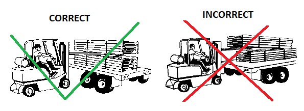
  • To prevent damage to cable tray, never pull cable tray from a truck trailer by chaining to the bottom rung and dragging cable tray out of the trailer

  • If the Material is found defective it shall not be installed and the cable shall be returned to the supplier for replacement. * Cable Tray and its accessories (pre-galvanized, hot dipped galvanized) shall be stored in a dry place, fully enclosed / ventilated store.

(4) INSPECTION OF MATERIALS:

  • Check The Material according to its Type, Size, Make * Visual inspection: * Type of Cable Tray * Type of Cable Tray Material * Type of Cable Tray Coating * Standard width of Cable Tray * Standard length of Cable tray * Cable Tray thickness * Flange height of Cable Trays * Proper painting / Galvanization and identification numbers of the cable trays * Physical Damages Inspection: * Damage on trays and ladders * Damage on galvanizing * Fittings and accessories are of proprietary type * Testing of galvanizing: * Uniformity of coating Thickness Test * Electrical continuity of connection * TRs not more than five year old from date of purchase order shall be reviewed for acceptance. Otherwise test shall be carried out.

BS EN ISO 1461

Table-1 Control Sample Size Related to Lot Size

Number of Lot

Min. Sample

1 To 3

All

4 To 500

3

501 To 1200

5

1021 To 3200

8

3201 To 10000

13

10000

20

Inspection Lot: Single Order or Single Delivery Order

ISO 1461:2009 TABLE-3

Minimum coating thickness and mass on samples that are not centrifuged

Article and its thickness

Local coating thickness (minimum)µm

Local coating mass (minimum)g/m2

Mean coating thickness (minimum)µm

Mean coating mass (minimum)g/m2

Steel > 6 mm

70

505

85

610

Steel > 3 mm to < 6 mm

55

395

70

505

Steel > 1.5 mm to < 3 mm

45

325

55

395

Steel < 1.5 mm

35

250

45

325

Casting > 6 mm

70

505

80

575

Castings < 6 mm

60

430

70

505

NOTE This table is for general use: individual product standards may include different requirements including different categories of thickness. Local coating mass and mean coating mass requirements are set out in this table for reference in such cases of dispute.

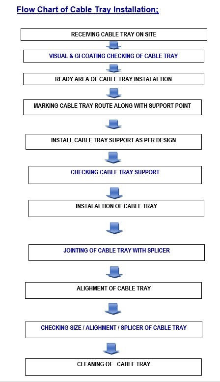
(5) SEQUENCE OF CABLE TRAY INSTALLATION WORKS:

(A) INSTALLATION OF CABLE TRAY:

(i) Shifting of Cable Tray on Site

  • Cable Tray shall be carefully unloaded or shifted to the site by using Crane/Hydra or by sufficient manpower and moved to a defined installation location. * Remove the packing and ensure that the Cable Tray is free from transportation damages * Check and ensure that approved drawings, the correct size and type of cable trays, trunking & accessories are ready for installation. * Ensure that cable trays/trunking and accessories received from site store for the installation are free of rusty parts and damages.

 (ii) Marking the Route:

  • Mark the route of Cable Tray and Trunking …
E

Method for Installation of Cable Tray-(PART 2)

METHOD FOR INSTALLATION OF CABLE TRAY-(PART 2)

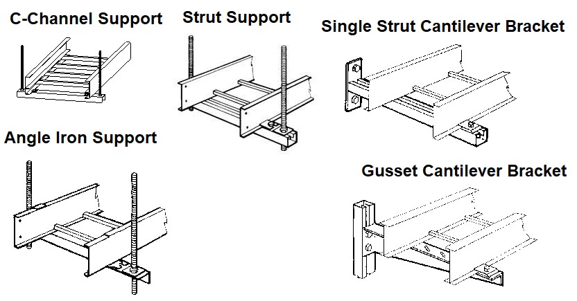
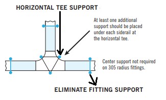
  • Horizon Tee Support: NEMA Standard * Supports for horizontal tee fittings should be located at a distance, no greater than 610 mm (24″) from each end of the fitting on the attached ladder. Fitting should also be supported once on each side rail. For 305 mm (12″) radius tees, place supports no greater than 610 mm (24″) from each end of the fitting on the attached ladder.

1

  • Horizon Cross Support: NEMA Standard * Supports for horizontal cross fittings should be located at a distance, no greater than 610 mm (24″) from each end of the fitting on the attached ladder. * Fitting should also be supported once on each side rail. For 305 mm (12″) radius cross, place supports no greater than 610 mm (24″) from each end of the fitting on the attached ladder.

2

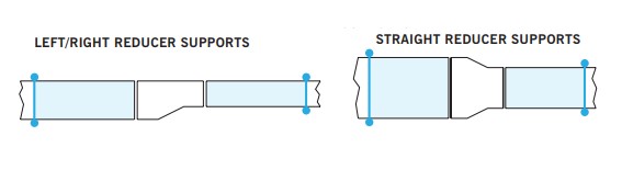
  • Reducer Support: NEMA Standard * Place horizontal supports (2) at a distance no greater than 610 mm (24″) from each end.

3

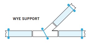
  • Horizontal Y Support: NEMA Standard * Place horizontal supports at a distance no greater than 610 mm (24″) from each of the three openings and at the midpoint of the fitting at 22.5°

 4

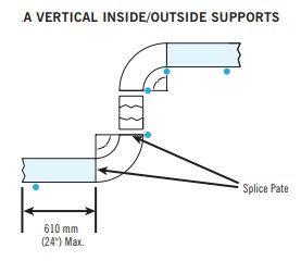
  • Vertical Inside / Outside Support: NEMA Standard * Vertical cable tray elbows at the top of runs should be supported at each end. At the bottom of runs, they should be supported at the top of the elbow and within 610 mm (24″) of the lower extremity of the elbows. Both Inside and Outside Fittings should be additionally supported at a distance no greater than (24″) from each end.

5

  • Offset Reducing Connection & Tray to Box / Floor Connection:

6

(IV) Cable Tray Installation:

  • Ensure that the Cable Tray’s, dimension, elevation and other fittings are properly leveled and that they are coordinated to the other services fixtures. * The width of Cable Tray/trunking/ladder should have sufficient width to take the cable without crowding and shall allow for future 25% space. The cables should not be stacked together. * If the conductors carried by trays or ladders are of various systems, the ELV and data processing or different insulation, the cable ladder or trays should be separate. Use insulating barriers where it is necessary. However, approval from the engineer is required. * Earth continuity shall be ensured throughout the length of the Trays and Trunking * Cable Tray Installation on Roof / Floor: * Cable tray should not be laid directly on the floor or roof. * Cable trays installed on roof shall be supported using Gl brackets or concrete blocks. * It should be mounted far enough off the floor or roof to allow drainage of water. * The cables to exit through the bottom of the cable tray. * Where cable trays are installed in roof or exposed to sunlight, factory made cover shall be fixed to protect the cables from direct sunlight. * Cable Trunking runs shall be arranged so that the lid is always on top or side. Lid shall be fixed to the trunking using factory made quick fix type clips. * Open ends of the trays / trunkings shall be capped with purpose made end caps. * Cable Tray Accessories: * Where cutting of the trays is needed, circular saws will be used. Cable tray cut edges will be rasped or welded if it is necessary, galvanized points will be cleaned then it will be sprayed with galvanizing spray immediately. * Cut portion of Trays and Trunking, shall be made free of sharp edges by filing and coated with zinc rich and top coat and jointed using fish-plates with bolts and nuts. * Any cutting on the cable tray to be done along the solid area and not across the perforation of the cable tray. Burrs needs to be removed and cuts need to be protected with anti-rust galvanized paint to prevent rust. * The minimum radius of Cable Tray should equal the minimum bending radius of the cables. Depending on the number of cables to be placed in the system it may be advantageous to use the next highest radius. * Installation of splice connectors * Splice connectors shall be located as recommended by the manufacturers. * Splice joints should be designed and placed so as to maximize the rigidity of the cable tray. * Splice connectors shall be attached by round / Hexa head bolts with the nuts and washers located on the outside of the tray or ladder unless otherwise specified by the manufacturer. * Thermal expansion splices shall be installed wherever expansion joints occur.

7

  • All straight joints, bends and offset connections shall be made neatly using standard fittings (fish plate and coupler). Only when these are inappropriate, fabricated bends/offsets shall be used.

(5) CLEANING OF WORK AREA:.

  • There should be a visual inspection of the trunking from inside side after installation. This is to be sure that it is free from Debris, burrs and waste materials. * There are no sharp edges that could cause damage to the cables during installment. * Galvanized coating damaged by excessively rough tr…
E

Method for Installation of Cable & Wire (Part-2)

METHOD FOR INSTALLATION OF CABLE & WIRE (PART-2)

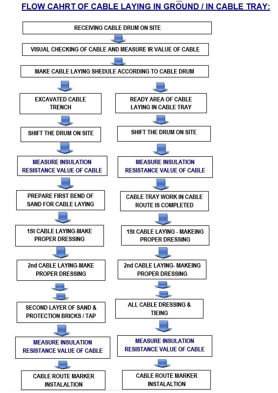
(A) CABLE LAYING IN EXCAVATED GROUND:

(A) FORMATION OF CABLE TRENCH.

  • Check the area of excavation by referring As Built drawing to find out crossing of any underground Services i.e. Gas Line, Water Line or other Cable. Check the indication marks, signs, manholes nearby area and find out the path of old services. * If there are structures adjacent to the work area, proper temporary supports shall be provided to the adjacent structure prior to start excavation. * Excavation near the existing electrical cables, instrumentation and control cables, sewer line, gas lines and any other service line shall take all necessary precautions to protect the services with proper supports & covers. * Ensure the working area at any confined space is free from any Hazardous Gas by proper Gas testing using the Gas testing instrument. * Required sign boards such as “DEEP EXCAVATION” “MEN WORKING”, “DANGER” and warning boards will be placed to indicate the excavation work. The area of excavation will be cordoned by using safety barricading to stop trespassers. * In open areas the excavation shall be carried out by using the machineries. * If the excavation level is below the local water table level suitable dewatering system shall be designed and installed in such a way that alterations and extensions to the system during operations are possible. * The width of the excavated Cable trench shall be as per specification or as per approved Drawings. * The trench shall be excavated up to the required depth of 0.76 Meter from the existing ground level or as per Specification or as per approved Drawing. * The Cable trench shall be kept dry during cable installation operation. The contractor shall deal with the dispose of water so as to prevent any risk to the cables and other materials. * Debris, rocks and unusable materials shall be removed from Excavated Trench on daily basis and it will dump at the approved dumping Location of from the site.

(B) FIRST LAYER OF SAND:

  • The bottom of the trench shall be backfilled with a layer of clean and fine sand bedding of 100mm thickness or as per the approved Drawing. * The fill material shall be tamped. Any hard material which could damage the cable will be removed * Inspection of sand bed will be carried out prior to commencement of cable pulling.

(C) CABLE LAYING:

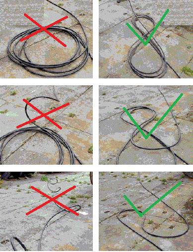
  • Cables are laid over the clean and fine First Layer of sand bedding. * Rollers must be used where cables are installed in an open trench using a pulling rope and eye; cable rollers are to be used at frequent intervals to support the cables and must never be more than 3 meters apart. * Care must be taken to ensure that the cable does not enter or leave the rollers at an angle that exceeds the bending radius of the cable. * The Pulling rope must be attached to the cable by a stocking grip with pulling eye. * The cable shall be drawn into the trench manually, before the pull commences, to prevent the winch to move along with the cable. * The cable shall be drawn into the trench smoothly with a minimum of stops and at an average speed of between 9 to 12 meters per minute, to avoid irregular movement. * Cables shall be arranged properly to minimize crossovers, twists. * All Cable shall be laying parallel to each other and cable dressing should be done properly * Cable identification tags shall be installed on both end of cable after the cable pulling.

(D) SECOND LAYER OF SAND:

  • The cables shall be backfilled with approved clean and fine Sand / backfill Material of 100mm thickness or as per the approved Drawing. * The fill material shall be tamped. Any hard material which could damage the cable will be removed * Inspection of sand bed will be carried out prior to commencement of Cable Protection layer.

(E) CABLE PROTECTION:

  • Cable protection tiles / Bricks / Warning Taps are laid above the second layer of dune sand filling.

(F) BACK FILLING:

  • Backfilling materials shall be free from stones or rocks (larger than 50 mm), fossil content, vegetation and its roots, waste materials, Material containing gypsum or other soluble salts greater than the allowable limits which might prevent proper compaction or cause to inadequately of performance. * Backfilling area shall be backfilled with approved material compacted in layers by suitable equipment like plate compactors, vibratory roller compactors, etc., until the specified density has been obtained. * Sufficient Water is poured to match the required Moisture content. * Intermediate cable markers to be firmly attached to the cables. * The thickness of fill material shall not exceed 150 mm where manual compaction methods are adopted.

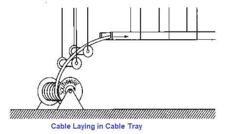
(B) CABLE LAYING IN CABLE TRAY / TRUNKING:

  • Before laying of Cable , Cable Tray work should be completed form the one end to other end of the Cable route * The cable tray must be cleaned and …
E

Method for Installation of Cable & Wire (Part-1)

METHOD FOR INSTALLATION OF CABLE & WIRE (PART-1)

PURPOSE:

  • The method explains the Procedures or activity for safely installation and Testing of MV cable in directly buries in ground, in trenches, in to cable trays or in underground ducts as per the standard Practice and Code.

GENERAL EQUIPMENT & TOOLS:

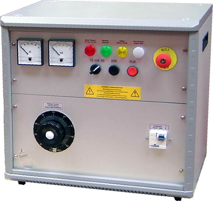
  • Testing Equipment for Cable * LV / HV Insulation Resistance tester (250V to 5KV) * Multi-meter * Continuity Tester * AC High Voltage Test Kit

STORAGE & MATERIAL HANDLING:

  • The storage area must be free from dust and Water leakages / seepages. * Manufacturer recommendation shall always be followed in loading/unloading and storing of Material. * Material and its accessories shall be unloaded handle with care in designated area of the Store (Do not directly drop to Ground) to avoid any damages. * Materials shall be stored in a dry place which is free from water or from weather effects and protection should be given to the material by means of covering the material with Tarpaulin sheet. * The Material will be stacked / unload in the site store on a proper stand on wooden loft on a flat surface at a sufficient height from Ground. * If Material are dispatch in packs or pallets, each pack or pallet shall be lifted individually with suitable lifting equipment. * The material shall be transported / Shifted in their original packing to Site location. * The cable drums shall be off-loaded at the site locations.

  • The cable drum should be visually inspected for damage, which may have occurred during transport. * During storage periodical rolling of drums once in 3 months done. Rolling shall be done in the direction of the arrow marked on the drum. * It should be ensured that both ends of the cable are properly sealed to prevent ingress/absorption of moisture by the insulation. * Protection from rain and sun shall be ensured. Sufficient ventilation between cable drums, should be ensured during storage. * The drums shall always be rested on the flanges and not on the flat sides. f. Damaged battens of drums etc. should be replaced, if necessary. * When cable drums have to be moved over short distances, they should be rolled in the direction of the arrow, marked on the drum * While transferring cable from one drum to another, the barrel of the new drum shall have a diameter not less than that of the original drum. * The manufacturer’s seal on the inner and outer cable ends should be examined and the condition of the sheath inspected for mechanical damage. * If the cable is found defective it shall not be installed and the cable shall be returned to the supplier for replacement.

INSPECTION OF MATERIALS:

  • Check The Material according to its Type, Size, Make * Inspection of Cable: * Type of Cable (HT /MV /LV) * Cable Operating Voltage * No of Cable Core (1 core,2core,3 core, 3.5 Core,4 core) * Type of Cable Core (Cu, Alu) * Type of Cable Material (PVC,XLPE) * Size of Cable * Length of Cable * Physical Damages Inspection: * Damage on Cable Drum * Damage on insulation of Cable * In case of any damages observed during inspection, the concern report will be issued and Material shall be returned to the supplier for replacement.

TESTING AND OF CABLE:

(1) INSULATION RESISTANCE TEST:

  • Following Insulation resistance test will be carried out by approved calibrated equipment. * At the Time of Cable drum receiving at the Store * Before Installation of Cable on Site. * After Installation of Cable on Site. * The Insulation Resistance values will be noted for Core to Core and Armor by DC High Voltage Tester (Megger) before following activities.

Voltage Class Test instrument Acceptance Value L/V Cable 1000 VDC >20 Mega ohm M/V Cable 5000 VDC >100 Mega ohm Control, Instrumentation, Communication cable 250 VDC >1 Mega ohm

  • The cables and conductors must discharged after Insulation Resistnce test.

(2) THE CONTINUITY TEST:

  • The continuity test would be carried out between * Phase to Phase, * Phase to Neutral, * Phase to earth and * Neutral to Earth. * The results would be recorded for records and future reference. * After the test, the end of the cable shall be sealed to prevent the ingress of moisture.

GENERAL STEPS FOR CABLING LAYING

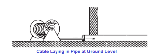
  • Shifting of Cable Drum at Working Location: * If a crane is used to unload / Shift cable, a shaft through the arbor hole or a cradle supporting both reel flanges should be used. * Forklifts must lift the reel by contacting both flanges. * Check and ensure that approved drawings, the correct size and type of Cable & accessories are ready for installation. * Ensure that Cable and accessories received from site store for the installation are free of rusty parts and damages. * Installation of Cable Drum on Jacks: * Check and ensure that the Correct Size and Type of Cable Drum and accessories are transported at the Site loca…
E

Reason for HT Cable Termination Kit Failure -PART-1

REASONS FOR HV CABLE TERMINATION KIT FAILURE- PART-1

INTRODUCTION:

  • High voltage cables are used in Electrical Network for Power Transmission and distribution. * Cable termination failure / faults are major problem in electrical networks. * Power cable joints and terminations are the weakest link in Electrical Network. The higher the voltage the more complexity in the cable joints and terminations hence more difficult to control thermal and electrical stresses. * There are many reasons that cause breakdown in cable termination. Like Poor Termination, Poor preparation of Semiconductive layer, Moisture, partial discharge, excessive bending, Not following instruction of Cable Termination kit’s manufacture.

MAIN REASON FOR HT TERMINATION FAILURE:

(A) WORKMANSHIP ERROR / ASSEMBLY ERRORS

  1. Excessive Bending of Cable 2. Crossing of Cable Core to each other 3. Sharp Corners 4. Not Proper Heating of Heat Shrinkable Sleeves 5. Excess Heating of Heat Shrinkable Sleeves 6. Loose Connections 7. Poor Installation of Mastic Tapes. 8. Not following Manufacture’s Instruction.

(B) POOR EARTHING OF CABLE

  1. Poor Termination of Steel wire Armored 2. Poor Earthing of Cable

(C) POOR PREPARATION OF SEMI CONDUCTIVE LAYER

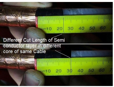
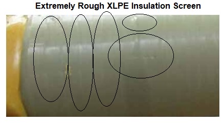
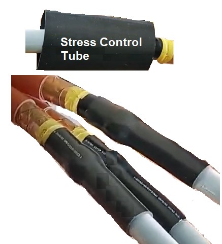
  1. Damaged of XLPE Insulation. 2. Damaged of Semi Conductive Insulation. 3. Incomplete removal of Semi conductive layer 4. Not Radial edge of Semi conductive layer 5. Wrong Cutback Length of Insulation / Semi conductive layer 6. Not Proper installation of Stress Control Tubes. 7. Extreme rough Surface of XLPE Insulation. 8. Not Proper Cleaning of XLPE Insulation Surface

(D) DAMAGE OF CABLE

  1. Damaged of Cable during Cable Termination Process

(E) WORSE ENVIRONMENT CONDITION

  1. Contamination of salt, dust, ash on Cable

(A) WORKMANSHIP ERROR / ASSEMBLY ERRORS

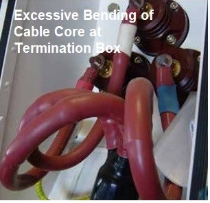
(1) EXCESSIVE BENDING OF CABLE

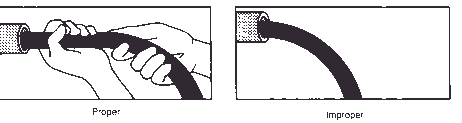
  • Excessive bending of the cable creates stress on the entire cable core, from the conductor to the shielding end. * This stress can cause micro voids in the insulator which become larger as stress is increased and lead to an eventual corona failure or dielectric breakdown.

A

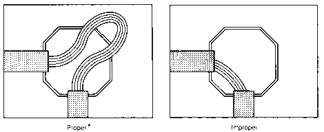
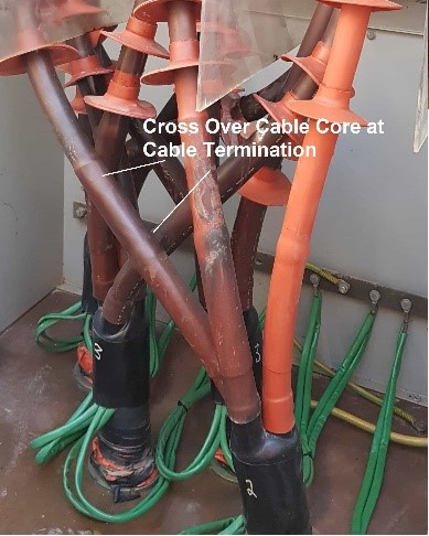
(2) CROSS OVER CABLE CORE / NOT PROPER DISTANCE BETWEEN EACH CORE.

  • Cable entry points through the cable gland plate to cable termination should be centralized / straight. * Crossing of cores to each other will increase stress over insulation and partial discharge will occur at the crossed cores of the HV cable causing failure of the cable termination. * if cores are too close and cross to each other at unscreened area results in the air “breaking down” at approximately 4kV on an 11kV cable, 6kV on a 24kV cable and 9kV on 36kV cable. * The anti-track heat shrink material then begins to erode due to the ionisation of the air, which over time will inevitably cause failure of the cable termination * Required to use proper Phase out the cable sections in the box.

B

(3) SHARP CORNERS (AT ARMOR OR AT LUGS):

  • Sharp corners generate highly stressed area which will be subjected to electrical discharge. * Normally Sharp edge will occur at armour bending or at Location of Lug’s crimping.

(4) NOT PROPER APPLICATION OF HEAT-ON-HEAT SHRINKABLE SLEEVES

  • Proper Amount Heat and direction of applied Heat is very important during Installation of Heat shrinkable Sleeve. * Some Sleeve need to be heated from central to both up and down direction while in some sleeve heat should be applied from bottom of sleeve to end termination direction. * Heating process firmly joint one layers (silicon rubber) to the others layer (XLPE, semiconductor and etc).

C

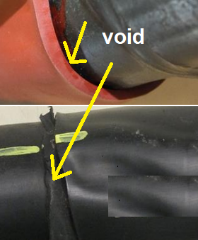
  • If during heating, voids remain between the layers, The voids may contain air, wet or contaminations which change equivalent circuit and formation of electric field distribution. * Electric field increases in the void or the layer of air and makes a high potential difference between both sides of the void. Insulation endurance weakness in the layer of air causes Partial Discharge (PD) and breakdown. * Make sure that the tubes are shrunk free from wrinkles

(5) EXCESS HEAT ON HEAT SHRINKABLE SLEEVES

  • Excessive Heat may damage the heat shrinkable sleeve.

(6) LOOSE CONNECTIONS

  • 20% to 25% of electrical failures due to poor termination and loose connections. * The poor termination / loose connection in an electrical system causes overheating at the joints which further leads to failure. * Loose connection is mostly raised due to Using improperly crimped tool / die for the cables. * Lugs of higher than recommended size used for termination will also in results of loose cable to lug joint.

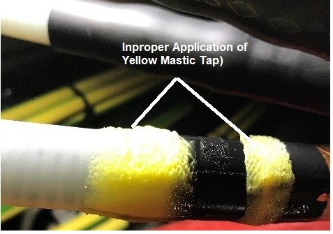
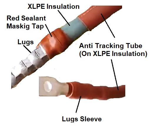
 (7) POOR INSTALLATION OF MASTIC TAPES.

  • Anti-Tracking mastic sealing tape is used in HV and MV terminations for providing a water-tight seal between heat shrink components and the cable parts. * Wrapping mastic tape around crotch and under lead cut on core to eliminate air and moisture. * Any improper w…
E

Reason for HT Cable Termination Kit Failure -PART-2

REASONS FOR HV CABLE TERMINATION KIT FAILURE- PART-2

(C) POOR PREPARATION OF SEMI CONDUCTIVE LAYER

(1) DAMAGE OF XLPE INSULATION:

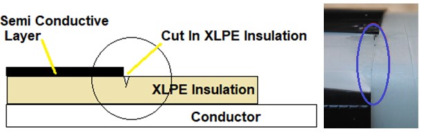
  • When unguarded knife or Glass is used for removing Semiconductor layer, there is a significant risk of cutting into the insulation at the screen edge. * Deep and dirty cuts and burrs in the insulation causing the XLPE insulation to be over stressed and this was ultimately caused the insulation failure. * A knife cut may be invisible but will certainly become a future failure, possibly immediately the cable system is energised but certainly after several months or years. The knife cut will likely be a point of partial discharge activity which leads to cable frailer. * Installers must be aware of this and pay great attention to this stage of the accessory installation process. * NEVER use an unguarded knife. This includes broken glass and any other object with a sharp unguarded edge.

 1

  • make sure that there are no deep dents formed on XLPE Insulation.

 (2) DAMAGED SEMI CONDUCTIVE LAYER

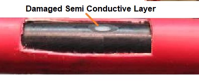
  • When unguarded knife or Glass is used for removing Insulation layer, there is a significant risk of cutting of Semiconductive layer of the Cable.

2

(3) INCOMPLETE REMOVAL OF SEMI CONDUCTIVE LAYER:

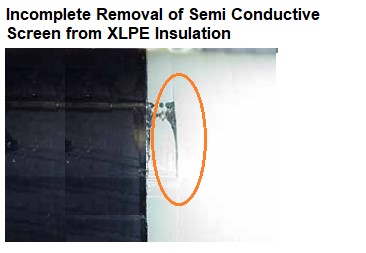
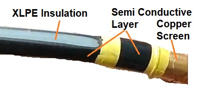
  • Correct / proper removal of the black conductive semi conductive screen layer covering the insulation is a critically and important stage in the preparation of cables Termination. * This is most important factor controlling the service life of a cable joint or termination. * The cable jointer should carefully examine the surface of the MV-HV cable insulation to ensure all black particles are removed. * The semi-con screen layer of MV-HV cable construction provides a smooth transition from the cable insulation to the metallic screen. * This semi conductive screen layer is extruded together with the insulation and the inner conductor screen. Its thickness is generally between 0.3 mm and 0.6 mm. * Here in figure, the semi conductive layer has been left (Not Properly removed) on the 11kV XLPE insulation which can cause surface tracking and eventual flash over. This occurred on 2 out 5 cable termination breakdowns.

3

  • Irregularities in removal of semi conductive screen can cause surface tracking, raise electric stress and eventual flash over the Cable.

 (4) IRREGULAR / SHARP (NOT RADIAL) EDGE OF SEMICONDUCTOR LAYER

  • The quality of the screen edge is very important for the performance of MV Cable in service. * Sharp edges in the insulation screen are a common error. The transition between the screen and the insulation must be smooth, achieved by a straight final cut. * Irregularities of semi conductive edge on the insulation are raised electric stress which will result of Cable Failure.

4

  • Non-radial, rough and jagged semi conductive screens with protruding points at the cutback will cause cable termination or joint failure.

(5) WRONG CUTBACK LENGTH OF INSULATION / SEMI CONDUCTIVE LAYER

  • The most common issue for Cable Termination failure is the incorrect insulation / semi conductive cutback dimensions. * The semi conductive cutback is the point of highest electrical stress in the termination. * Jointer should strictly follow the manufacturer’s instructions Manual for dimension of cutback length from the end of the insulation to the semi conductive layer. * If This length is either more or less caused the termination kit’s electrical stress control Tube and void filling compound to fall well below the semi conductive cutback.

5

(6) NOT PROPER INSTALLATION OF STRESS CONTROL TUBES.

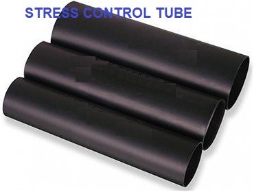
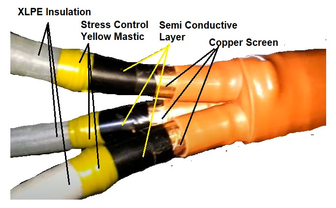
  • Stress control tube is used to achieve more uniform distribution of the Electrical field lines. It should be installed at correct location of cut back as per Instruction manual of Termination Kit’s manufacture. Any deviation in location would lead to Cable termination frailer.

(7) ROUGH SURFACE OF XLPE INSULATION.

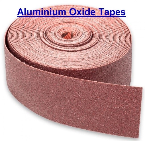
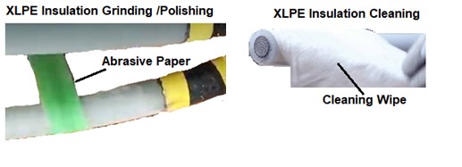
  • The XLPE insulation surface must be smooth to avoid sir gaps where partial discharge can occur. * Use long and thin strips of grinding paper. Perform carefully and do not extremely grind the insulation screen. * It is good practice to smooth any minor surface roughness using abrasive cloth (preferably aluminum oxide type).

6

(8) NOT PROPER CLEANING OF XLPE INSULATION SURFACE:

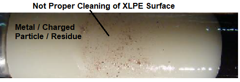
  • Insulation layers should be cleaned during installation, because any conductive particles to spread all over the insulation, causing partial discharges. * Wet or polluted surface of XLPE Insulation may cause a fault in cable terminations. * The jointer should move the cable’s wipe away from the cable end towards the semi-con screen to remove fine particles on the edge of the cable screen, not on the insulation otherwise conductive particles or dirt could be dragged to the insulation and cause discharge. * Never use the same side of a cleaning tissue twice. The insulation must be clean of conductive par…
E

HV Cable Termination Method and Precaution-PART-1

HV CABLE TERMINATION METHOD AND PRECAUTION. (PART-1)

INTRODUCTION:

  • Power cable is most important part of power transmission and distribution systems. * Terminations and joints are the essential part for the power cables. It makes connections between Cable or between Cable and electrical apparatus. * Cable terminations make physical and electrical connections between the cable and the equipment to flow electricity in the desired manner. * Cable terminations are weak parts for electrical system and most of the cable faults happen at this section, hence the quality of cable terminations directly affects the safe operation of the cable lines. The mistake will cause troubles, widespread power outages and cause great loss of finance, the people’s life and property. * There are three types of cable terminations. it can be heat-shrink type, cold-shrink type or pre-moulded push on type cable terminations.

TYPE OF CABLE TERMINATION:

  • There are various types of High / Medium Voltage cable termination for substation switchgears, transformer, poles, and cable boxes. * Termination Kit are classified by its application. * It can be pre-molded push-on, cold shrink or heat shrinkable type. * Selecting the appropriate termination method is essential for maintaining the mechanical integrity of the cable and it depends on the cable types, operating parameters, voltage applications and site conditions. * Each technology has specific advantages depending on the needs of the user.

Heat shrinkable terminations:

  • It names suggests that it required Heat and have shrinkable type tubing. * when we applied heat (with an electric or gas heat gun) to shrink tube. It expanded shrinkable tubes to the size of the substrate beneath and enabling quick and easy installation. * Material: * Heat shrinkable products are usually made from polyolefin type plastics which have been modified to give additional properties such as improved weathering and enhanced insulation levels. * Heat Shrink is resistant to most chemicals. It will become rigid once it has been recovered and making it a good option for mechanical protection. * Application: * Use on low and medium voltage cables, * Heat shrink termination kits can be used for XLPE cable in both indoor and outdoor applications, even for extreme hazardous atmospheric conditions. * The cable terminations provide non-tracking stress control connections for medium to high voltage cables with water, UV, erosion and corrosion resistant performance. * Advantage: * When stored correctly, there is unlimited shelf life for the product. * Drawback: * the Material rigidity prevents flexing with the cable during normal operation hence an effective environmental seal cannot be maintained without the mastic tapes.

Cold shrink terminations: 

  • It names suggests that it does not require heat. * They can be used for medium-high cable installations which do not require naked flame or heat source to install especially in explosive atmospheres. * By removing the supporting cord during the installation process causes the tube to shrink so that it fits onto the desired place. * The cold shrinkable cable terminal offers excellent insulation and high resilience. * Material: * Cold Shrinkable products are made from elastomeric materials such as Silicon or EPDM rubbers, which are pre-stretched onto a tubular hold-out made from plastic tape in a tight spiral. * By unwinding the spiral tube, the material recovers to its original size. * Application * The cold shrinkable cable joints are especially suitable for installation in hazardous environment, such as coal mine, oil field etc, where fire is strictly prohibited. * Advantage: * The Cold Shrink eliminate any heat source required for installation. * The rubber material will follow the normal expansion and contraction of cables without need for additional adhesives or mastics. * Disadvantage: * Care is needed to store product and there is a finite shelf life.

Push On type termination:

  • Similar to Cold Shrink, these are made from elastomeric material and are not expanded before installation. * The product is applied by sliding onto cable cores with the use of silicone grease as a lubricant. * It has similar benefits to Cold Shrink, but with restricted application diameter range.

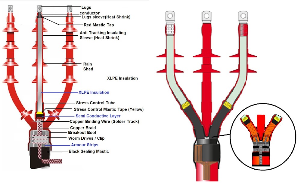
PARTS OF TERMINATION KIT

(A) Environment Sealing Shrinkable Tubes:

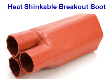
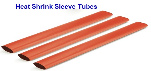
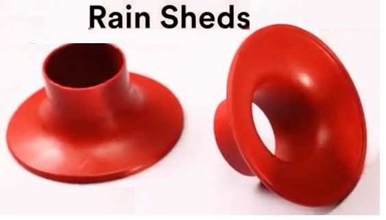
  • Breakout Boot * Anti-tracking Heat Shrink Sleeve Tubes * Stress Control Tubes * Lug Sealing Tubes * Rain Sheds

(B) Mastic Taps:

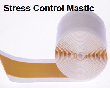
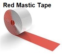
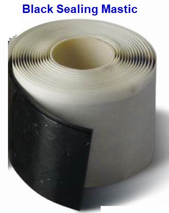
  • Stress Control Yellow Mastic * Red Sealing Mastic * Black Sealing Mastic * PVC Insulation Tape

(c) Earthing:

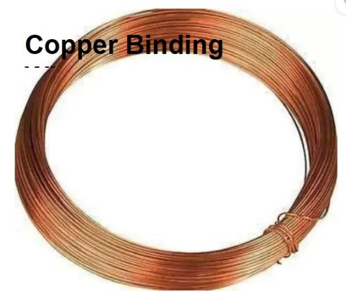
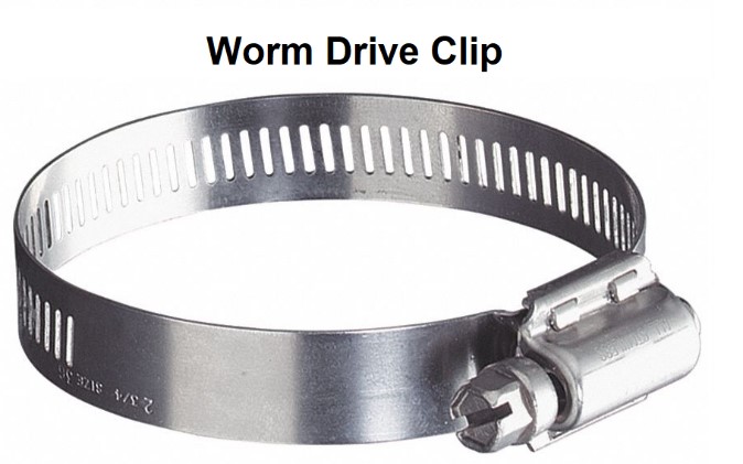
  • Worm Clips: * Tinned Copper Braid * Copper Binding Wire / Small Copper Braid

(D) Cleaning Accessories

  • Cleaning Solvent * Aluminum Oxide Tape * Silicon Grease

(E) Other:

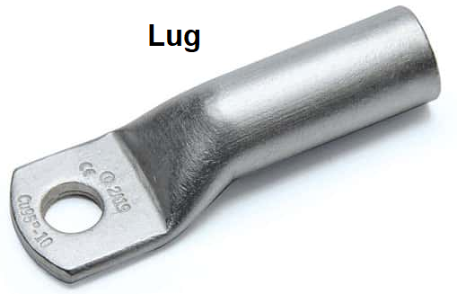
  • Lugs * Nylon Thread

(1) HEAT SHRINKABLE BREAKOUT BOOT

  • PURPOSE:

  • Breakouts Boot is used t…

E

HV Cable Termination Method and Precaution-PART-2

HV CABLE TERMINATION METHOD AND PRECAUTION. (PART-2)

BASIC STRUCTURE OF HIGH VOLTAGE CABLES

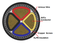
  • High-voltage cables generally consist of nine layers.

aaa

  • The basic structure of high voltage cables is

(1) OUTER SHEATH:

  • It protects cable from the moisture and environment. It also provides protection against mechanical impact on cable. * Outer sheath material is mostly Polyethylene

(2) ARMOR LAYER.

  • Armor provides mechanical Strength to the cable, certain resistance to external force, and prevents animal bite, external mechanical impact on cable.

(3) INNER SHEATH:

  • Inner protective sheath can keep Cable XLPE Insulation layer away from water, air and other objects, avoiding moisture and mechanical injury on internal insulation layer. * It protects the cable core. * Inner Sheath Material is same as outer sheath material, mostly Polyethylene

(4) PACKAGE AND FILLER LAYER.

  • It helps to organizes several cable cores into circular shape, for the convenience of packaging and cabling. * It also provides protection to the cable Core.

(5) COPPER SHIELDING SCREEN.

  • The main function of copper screen is to equalize the electric field and help improve the electric field distribution. * The other function is to ground the short circuit current. * When cable is charged it’s produced strong electrical filed around the core, Copper Shielding equalize this electrical filed and improve uniformity of electrical field distribution surrounding the core which restrict the interference of strong electric field around on core in the cable. * Hence, if copper shielding layer in cable doesn’t exist, then insulation breakdown between core and core will be damaged.

(6) SEMI CONDUCTIVE LAYER (OUTER SEMI CON LAYER).

  • There may be small clearance or air gap between in XLPE insulation and copper shielding screen which is one of the main factors causing partial discharge. * Semi Conductive material have good contact properties hence semiconductive layer is provided between XLPE Insulation and copper screen to avoid the partial discharge between insulation layer and protective layer.

(7) XLPE INSULATION LAYER.

  • The cable insulation provides electrical insulation to the conductor at voltage from the outer screens at ground potential. * The insulation will be of sufficient thickness to withstand the electric field under the rated and transient operating conditions. * XLPE (cross-linked polyethylene) is good insulating materials. * XLPE has high breakdown strength, high insulation resistance, low dielectric loss, excellent tree discharge- resistance performance and long insulation performance period, etc.

(8) CONDUCTOR SHIELDING LAYER (INNER SEMI CON LAYER).

  • Conductor shielding layer can improve the electric field distribution. * This layer reduces the probability of occurrence of partial discharge. * The cable conductor is made stranding of wires hence it surface is not smooth which creates air gap between insulation layer and conductor. This will cause the concentration of electric field. * Conductor is covered by Inner Conductor shielding layer of semiconductor materials on the surface of the conductor for good contact with insulation layer.

HV CABLE TERMINATION PROCEDURE:

GENERAL INSTRUCTIONS

  • Use a propane gas torch with a soft yellow flame for shrinking components. * Avoid a pencil type flame which is caused by unregulated supply * Keep the flame on the moving direction to ensure even shrinkage of all the materials and also helps to reduce scorching * Ensure that all components are kept clean and grease free during installation * Allow to cool before applying any mechanical strain * Read the instructions carefully before starting. * Clean and degrease all parts which will be in contact with tapes and adhesives. * Personnel should be proficient and knowledgeable for preparing and installing medium voltage terminations.

 (1) REMOVE OUTER CABLE INSULATION SHEATH:

  • Calculate approximate Terminate length of Cable from following Table.

2

Voltage Indoor (L) Outdoor (L) x 7.2KV 650mm 700mm Length 0f Lugs +5mm 12KV 650mm 700mm 17.5KV 650mm 700mm 24KV 700mm 800mm 36KV 800mm 900mm The “L” dimension should not be longer than the distance between bushing centers and base plate.

3

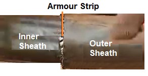
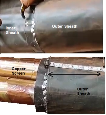
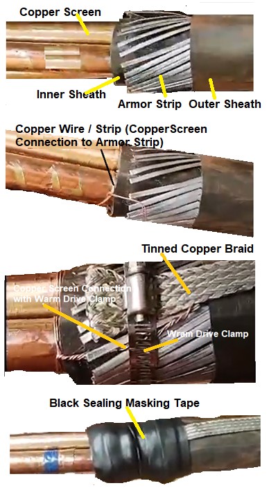
  • Strip of and removed Outer Sheath of Cable for Length “L”. * Removed Armored from Length “L”. * Make smooth edge of Sharp armour. * Bend / Fold Armour up to 50mm. * Bind Armour on the outer sheath with use of Copper Wire / Clamp.

(2) REMOVE INNER CABLE INSULATION SHEATH:

  • Removed Inner Cable Sheath 10mm length from Armour with the help of knife. * Removed extra parts of cable which used to make cable round, i.e., Filler, Binding rope / Strip

4

(3) EARTHING ARRANGEMENT OF COPPER SCREEN.

  • Marking with the help of tape from100mm length from inner sheath on Cu Screen. * Removed extra Copper Screen from this marking tap t…
E

Difference between PVC- LSF-LSHF- FR- FRLS -FRLSH Cables. (PART-1)

DIFFERENCE BETWEEN PVC- LSF-LSHF- FR- FRLS -FRLSH CABLES. (PART-1)

INTRODUCTION:

  • Due to lack of standardization and lack of awareness. While selecting of Cable, there is a lot of confusion and misunderstanding regarding the terminology associated with cables in terms of “LSF / LS” (Low Smoke), “LSZH / LSHF (Low Smoke Halogen Free),” FR” (Fire Retardant),”FR” (Fire Resistance) “FRLS” (fire resistant, low smoke), “FRLSZH” (Fire retardant Halogen-Free).

CABLE / WIRE TERMINOLOGY

  • According to type of Insulation Material around the conductor, we can classify Cables / Wire in Three main Categories PVC, Zero Halogen and Fire Retardant. * According to application we can mainly classified in to Two categories

(A) Non-Fire Rated Cable

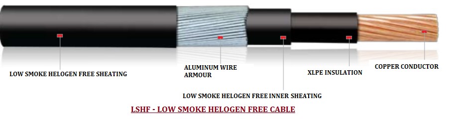
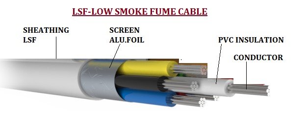
  1. PVC = Polyvinyl Chloride 2. LS / LSF = Low Smoke / Low Smoke Fume 3. LSHF / LSZH / LSNH = Low Smoke Halogen Free / Low Smoke Zero (No) Halogen 4. LH / HF = Low Halogen / Halogen Free

(B) Fire Rated Cable

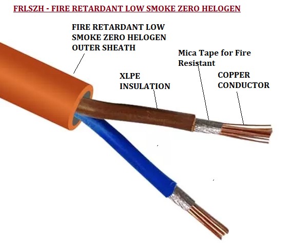
  1. FR =Fire Retardant 6. FR =Fire Resistance 7. FRLS = Fire Resistant, Low Smoke 8. FRLSH= Fire Resistant, Low smoke, Low Halogen 9. FRLSZH / NHFR / ZHFR / HFFR = Fire Retardant Low Smoke Zero Halogen / Non (Zero) Halogen Free, Fire retardant 10. HRFR=Heat Resistance Fire Retardant
  • PVC, FRLS and FP cables, have conductors and insulation to manage the electrical current and voltage. Some also have extra physical protection, like steel wire armour. * PVC and FRLSH cables are different insulating materials around conductors for different application and performance.

  • The properties that distinguish one electrical insulation from the other are * (1) dielectric strength or break down voltage * (2) maximum permissible temperature * (3) dielectric loss * (4) permittivity; and some special properties to suit the application. * FRLS / FRLF is the quality of insulating material. It may be PVC or XLPE.

(A) NON-FIRE RATED CABLE

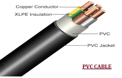
(1) PVC CABLE:

  • PVC (Polyvinyl Chloride) cables is usually made up of a PVC compound as an insulating Material. * PVC insulation has a temperature limit of about 70°C. From the point of view of maximum permissible temperature, it belongs to the lowest class of insulation, yet it serves the purpose as the voltages and power ratings involved are relatively low. * While burring of PVC in case of Fire produces dense of black smoke and produce large amount of toxic gas and cocktail of harmful chemicals. * Smoke: * Burning PVC has been reduced visibility in the surrounding area by 50% within 10 minutes. After 30 minutes, visibility can be reduced by as 90% * This reduced visibility could make it very difficult to escape a burning Area / Building. * The smoke and fumes produced during a fire can be more dangerous to people than the fire itself. * Toxic Chemicals: * Burning PVC produces a number of toxic chemicals, but the most problematic is hydrogen chloride (HCI). PVC emits approximately 28% of Hydrogen Chloride (HCI). * In natural state HCL is a pungent, almost colorless gas, which forms into white vapor clouds on contact with air. * Furthermore, when mixed with water it changes state yet again to form Hydrochloric Acid, whether it’s in gaseous, vaporized or liquid state it’s a highly toxic and corrosive substance. * There are numerous harmful effects that HCl can have on a person. If inhaled the lining of the throat can be irritated to such an extent that it swells, making breathing extremely difficult. * Contact with the eyes can be responsible for anything from severe irritation to permanent damage to the corneas. Similarly, lips and mucous membranes may be burned or even ulcerated, the severity dependent on the concentration of HCl and length of exposure. * Taking into account the combined effects on someone of the smoke and HCl produced during the burning process, it’s difficult to see and the victims have been rendered unconscious long before the flames have reached them. * Some extent Fire Retardant property: * PVC is resistant to Fire ignition. * PVC (polyvinyl chloride) is naturally Fire Retardant due to chlorine base. It contains a large number of chlorine ions in the molecular structure and these are particularly difficult to break off when exposed to heat. * If it does catch fire, PVC has a particularly slow spread of flame. PVC has one of the lowest flames spread ratings, meaning that it won’t typically contribute to the spread of a fire * The temperature required to ignite rigid PVC is more than 150 deg C higher than that required to ignite wood. The ignition resistance of common flexible PVC formulations is lower, but with specialized formulations it may be significantly increased. * The fire in the gets extinguished immediately on removal of the fire source. * In the Plant or Building, PVC cables are bunched in the cable shaft or on cable trays. In case of fire in these cables the fire becomes self-sustaining. * Moreover, due to the…
E

Difference between PVC- LSF-LSHF- FR- FRLS -FRLSH Cables. (PART-2)

DIFFERENCE BETWEEN PVC- LSF-LSHF- FR- FRLS -FRLSH CABLES. (PART-2)

(B) FIRE RATED CABLE (RETARDANT / RESISTANCE CABLE)

  • Fire is one of the biggest risks in factories, public place and a majority of them occur due to electrical faults. * The terms Fire Resistant and Fire Retardant (both are commonly referred to as FR) terms are very similar and misused or confusing a lot. * Both are different in structure, in materials, in Application and react even differently in the event of a fire. If we required one but select other can lead the problem.

(1) FIRE RETARDANT CABLES 

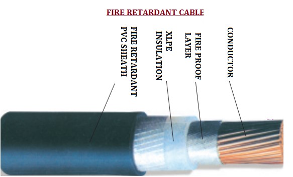
  • Insulating Material of Fire Retardant Cable is chemically treated to Retard or Slowdown ignition or Burning of Fire hence slow down the spreading of fire. It also actually self-extinguishes when exposed to an open flame. * Flame-retardant Cable is characterized by delaying the spread of flame along the cable so that the fire does not expand. * Fire-resistant cables and flame-retardant cables are different in structure and materials. * The basic structure of the flame retardant cable is: * The insulation layer uses flame retardant. * The inner sheath and outer sheath are made of flame retardant. * The tape and filling use of flame retardant material.

11

Advantage:

  • Low Cost compared to Fire Resistance Cable. * Produce Low Smoke

Disadvantage:

  • By Adding Fire Retardant Material / Filler in PVC it decreases insulation property at least 10% compare to normal PVC, however its conductor temperature withstanding capability (during overload) remains only at 70 deg C same as ordinary PVC cables.

Applications:

  • Control Wiring of Building * Fire Alarm Circuit

(2) FIRE RESISTANT CABLES

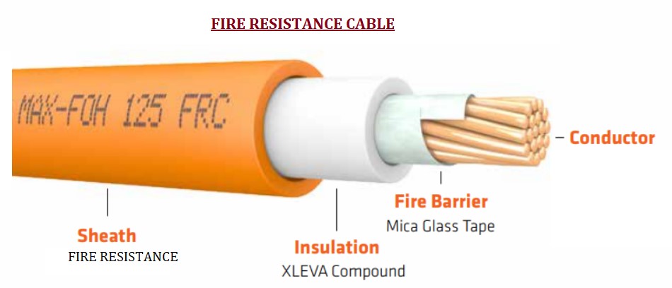
  • The Fire resistance materials (non-flammable.) are designed to prevent / Resist the spread of fire (self-extinguishing) and will not melt or drip when in close proximity to a flame. * Because it self-extinguishes once the source of ignition is removed and does not melt or drip. Fire-resistant cables can maintain normal operation for a certain period under flame burning conditions and maintain the Circuit integrity and continue to work for a specified period of time under defined conditions hence improving the chances of escape and survival. * Because of Fire resistant fabrics are not usually made from 100% flame resistant materials, they will burn, but will do so very, very slowly and are often self-extinguishing. * A Fire-resistant cable is a cable that can maintain safe operation for a certain period under flame-burning conditions. Fire-resistant wires are widely used in high-rise buildings, subways, underground shopping malls, power stations, and important industrial and mining enterprises related to fire safety and fire rescue. For example, power supply wires and control wires for firefighting facilities. * Fire-resistant cable is divided into class A and class B. * Class B: Class B cable can be in 750 ℃ to 800 ℃ flame and rated voltage to withstand burning for at least 90min, and the cable is not broken. * In the refractory layer to improve the manufacturing process and increase the refractory layer and other methods based on * Class A: Class A fire rated cable can be 950 ℃ to 1 000 ℃ flame and rated voltage to withstand burning for at least 90min and the cable is not punctured. * Class A fire-resistant cable fire performance is better than class B. * Mineral Insulated Cable (MI): mineral insulated cable is a better performance of fire-resistant cables made of copper core, copper sheath, magnesium oxide insulation material processing, referred to as MI (mineral insulated cables) cable. * MI cable has good fire resistance characteristics and can work for a long time under 250 ℃ high temperature, but also explosion-proof, strong corrosion-resistance, high flow rate, radiation resistance, high mechanical strength, small size, lightweight, long life, and smokeless. However, the price is high. The process is complicated, the construction is difficult in the oil irrigation area, important public buildings, high-temperature places, and other fire-resistant requirements, and the economy can accept the occasion and use fire-resistant cable.

22

Advantage:

  • Produce Low Smoke compared to Fire Retardant Cable.

Disadvantage:

  • High Cost compared to Fire Resistance Cable. * By Adding Fire Retardant Material / Filler in PVC it decrease insulation property at least 10% compare to normal PVC, However its conductor temperature withstanding capability (during overload) remains only at 70 deg C same as ordinary PVC cables.

Applications:

  • In Fire Fighting System, * In Fire Alarm Circuit

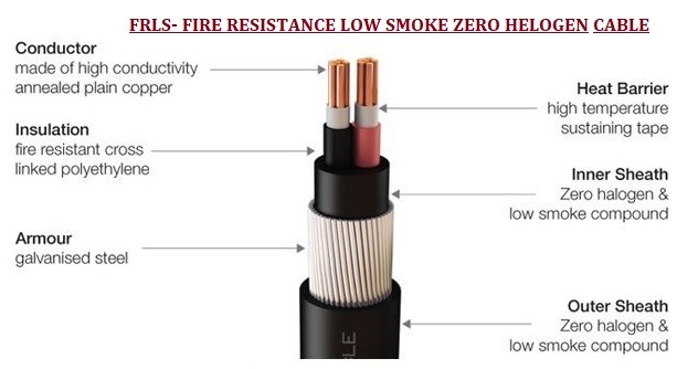
(3) FRLS (FIRE RETARDANT LOW SMOKE)

  • To overcome these deficiencies of FR Cable, FRLS Cable was developed. * FRLS has special flame retardant, low smoke emitting and toxic fumes suppressing properties. * In FRLS Cable, inner sheath and/or outer sheath is made material …