Site logo
Electrical Engineering Academy
Cover image
E

Which Class of Wire need to be used for House Wiring

WHICH CLASS OF WIRE NEED TO BE USED FOR HOUSE WIRING

November 9, 2025 Leave a comment

DIFFERENT CLASS OF CONDUCTOR

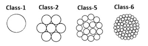
  • As per IEC 60228, Electrical wires/cables are classified into different classes according to the conductor’s flexibility, conductor hardness & thermal effects. * There are four classes of flexibility for electrical cables * Class 1 = Solid conductor= ideal conductors for permanent installations. * Class 2 =Stranded conductor= conductors designed for fixed installation. * Class 5 =Flexible conductor= preferred to used where flexibility is required, for movable equipment , where there is vibration in equipment. * Class 6 =Very Flexible conductor= highly flexible conductors used in robotics, flexible codes. * Classes 3 and 4 are not described in IEC 60228. * The most basic type of conductor is a single, solid wire (Class 1). It provides a smaller diameter, the largest Cross-Sectional Area (CSA), and the clearest signal, it is mechanically fragile and susceptible to breakage after repeated bending cycles. * To improve flexibility, wires are stranded together (Class-2, Class-5, Class-6). Class 2 is a multi-wired conductor, while classes 5 and 6 are fine or ultra-fine wired conductors. The IEC standard specifies values such as the maximum diameter and maximum resistance for the individual wires. * The more wires that are stranded together to make a given size, the more flexible the conductor will be. This indicates that a higher class corresponds to a greater number of strands within the conductor. Additionally, stranded wires are significantly easier to manipulate and bend during installation compared to a single wire of equivalent cross-section. * Classes 1 and 2 are intended for use in cables for fixed installations. On the other hand, Classes 5 and 6 are designed for use in flexible cables and cords but may also be used for fixed installations.

(A) CLASS 1: SOLID CONDUCTORS

  • Construction: Single Conductor, solid copper wire. * Flexibility: Rigid and non-flexible. the cable should not be bent more than about four times its diameter * Characteristics: High electrical conductivity and resistance to corrosion, but less suitable for environments requiring flexibility. * Advantages: Less expensive than cables with multiple wires * Disadvantages: Less suitable for applications involving movement. * Heat and Losses: Class 1 wires are more efficient for fixed wiring due to lower resistance and heat generation. * Applications: Typically used in permanent, stationary installations, House wiring where the conductor will not be subject to frequent movement or low flexibility is not a problem such as in building wiring and power distribution. * They are often used when cables with larger cross-sections are required for fixed installations. They are not suitable for very flexible cables, which are used, for example, in continuously moving objects such as robotic arms in industrial production

(B) CLASS 2: STRANDED CONDUCTORS

  • Construction: Composed of multiple smaller copper wires twisted or braided together to form a single conductor. * Flexibility: More flexible than Class 1, allowing for some movement without breaking or damaging the wire. * Characteristics: Offers a balance of flexibility and durability but may not be as conductive as a solid conductor of the same gauge. * Advantages:Lower electrical resistance and less heat buildup under load. * Disadvantages:Less suitable for applications involving movement. * Heat and Losses:Class 2 wires are more efficient for fixed wiring due to lower resistance and heat generation. * Applications: Primarily used for fixed installations like permanent building and house wiring and for industrial applications with increased cable flexibility requirements.

(C) CLASS 5: FLEXIBLE CONDUCTORS

  • Construction: Consists of many fine copper wires (often tinned for corrosion resistance) twisted together, making the conductor highly flexible. * Flexibility: Extremely flexible, designed for applications where the conductor needs to withstand frequent movement, bending, or vibration without damage. * Characteristics: High flexibility, durable against wear and tear, but may have slightly lower conductivity compared to solid conductors due to the finer strands. * Advantages:Superior flexibility. * Disadvantages:Higher electrical resistance, which can result in greater heat loss and voltage drops. * Heat and Losses:Class 5 wires are not efficient for fixed wiring due to higher resistance and heat generation compared to Class-2. * Applications: Used in situations where more flexibility is required, such as in circuits that may need to be bent, coiled, or moved occasionally. Ideal for portable appliances and equipment that move constantly like portable cords, flexible cables, and power tools that require a durable,…
F

what is Power Factor & Automatic Power Factor Correction

AUTOMATIC POWER FACTOR CORRECTION

WHAT IS POWER FACTOR?

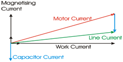
  • Power Factor Definition: Power factor is the ratio between the KW and the KVA drawn by an electrical load where the KW is the actual load power and the KVA is the apparent load power. It is a measure of how effectively the current is being converted into useful work output and more particularly is a good indicator of the effect of the load current on the efficiency of the supply system. * All current flow causes losses both in the supply and distribution system. A load with a power factor of 1.0 results in the most efficient loading of the supply. A load with a power factor of, say, 0.8, results in much higher losses in the supply system and a higher bill for the consumer. A comparatively small improvement in power factor can bring about a significant reduction in losses since losses are proportional to the square of the current. * When the power factor is less than one the ‘missing’ power is known as reactive power which unfortunately is necessary to provide a magnetizing field required by motors and other inductive loads to perform their desired functions. Reactive power can also be interpreted as wattles, magnetizing or wasted power and it represents an extra burden on the electricity supply system and on the consumer’s bill. * A poor power factor is usually the result of a significant phase difference between the voltage and current at the load terminals, or it can be due to a high harmonic content or a distorted current waveform. * A poor power factor is generally the result of an inductive load such as an induction motor, a power transformer, and ballast in a luminary, a welding set or an induction furnace. A distorted current waveform can be the result of a rectifier, an inverter, a variable speed drive, a switched mode power supply, discharge lighting or other electronic loads. * A poor power factor due to inductive loads can be improved by the addition of power factor correction equipment, but a poor power factor due to a distorted current waveform requires a change in equipment Design or the addition of harmonic filters. * Some inverters are quoted as having a power factor of better than 0.95 when, in reality, the true power factor is between 0.5 and 0.75. The figure of 0.95 is based on the cosine of the angle between the voltage and current but does not take into account that the current waveform is discontinuous and therefore contributes to increased losses. * An inductive load requires a magnetic field to operate and in creating such a magnetic field causes the current to be out of phase with the voltage (the current lags the voltage). Power factor correction is the process of compensating for the lagging current by creating a leading current by connecting capacitors to the supply. * P.F (Cos Ǿ)= K.W / KVA Or * P.F (Cos Ǿ)= True Power / Apparent Power. * KW is Working Power (also called Actual Power or Active Power or Real Power). * It is the power that actually powers the equipment and performs useful work. * KVAR is Reactive Power. * It is the power that magnetic equipment (transformer, motor and relay)needs to produce the magnetizing flux. * KVA is Apparent Power. * It is the “vectorial summation” of KVAR and KW.

DISPLACEMENT POWER FACTOR CORRECTION.

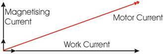
An induction motor draws current from the supply that is made up of resistive components and inductive components. The resistive components are: 1) Load current. 2) Loss current. And the inductive components are: 3) Leakage reactance. 4) Magnetizing current.

  • The current due to the leakage reactance is dependent on the total current drawn by the motor, but the magnetizing current is independent of the load on the motor. The magnetizing current will typically be between 20% and 60% of the rated full load current of the motor. The magnetizing current is the current that establishes the flux in the iron and is very necessary if the motor is going to operate. * The magnetizing current does not actually contribute to the actual work output of the motor. It is the catalyst that allows the motor to work properly. The magnetizing current and the leakage reactance can be considered passenger components of current that will not affect the power drawn by the motor, but will contribute to the power dissipated in the supply and distribution system. * Take for example a motor with a current draw of 100 Amps and a power factor of 0.75 The resistive component of the current is 75 Amps and this is what the KWh meter measures. The higher current will result in an increase in the distribution losses of (100 x 100) /(75 x 75) = 1.777 or a 78% increase in the supply losses. * In the interest of reducing the losses in the distribution system, power factor correction is added to neutralize a portion of the magnetizing current of th…
F

Harmonics and It’s Effects

HARMONICS AND IT’S EFFECTS

WHAT IS HARMONICS?.

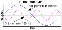
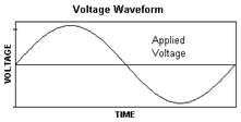
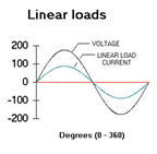
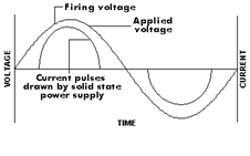
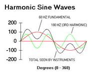
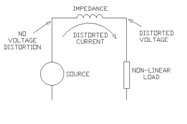
  • Harmonics are sinusoidal voltages or currents having frequencies that are whole multiples of the frequency at which the supply system is designed to operate (e.g. 50Hz or 60 Hz). * Harmonics are simply a technique to analyze the current drawn by computers, electronic ballasts, variable frequency drives and other equipment which have modem “transformer-less” power supplies. * There are two important concepts to bear in mind with regard to power system harmonics. * The first is the nature of harmonic-current producing loads (non-linear loads) and the second is the way in which harmonic currents flow and how the resulting harmonic voltages develop. * There is a law in electrical engineering called Ohm’s Law. This basic law states that when a voltage is applied across a resistance, current will flow. This is how all electrical equipment operates. The voltage we apply across our equipment is a sine wave which operates 60 Hertz (cycles per second).

  • To gene

F

Vibration Damper in Transmission Line

VIBRATION DAMPER IN TRANSMISSION LINE

VIBRATION DAMPER IN TRANSMISSION LINE:

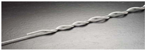
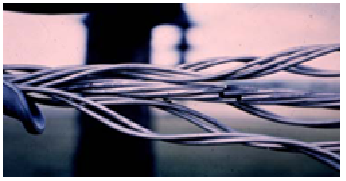
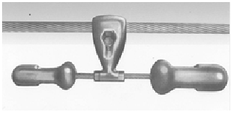
  • Wind-induced vibration of overhead conductors is common worldwide and can cause conductor fatigue Near a hardware attachment. * As the need for transmission of communication signals increase, many Optical Ground Wires(OPWG) are replacing traditional ground wires. * In the last twenty years All Aluminum Alloy Conductors (AAAC) have been a popular choice for overhead conductors due to advantages in both electrical and mechanical characteristics. Unfortunately AAAC is known to be prone to Aeolian vibration. * Vibration dampers are widely used to control Aeolian vibration of the conductors and earth wires including Optical Ground Wires (OPGW). * In recent years, AAAC conductor has been a popular choice for transmission lines due to its high electrical carrying capacity and high mechanical tension to mass ratio. The high tension to mass ratio allows AAAC conductors to be strung at a higher tension and longer spans than traditional ACSR (Aluminum Conductor Steel Reinforced) conductors. * Unfortunately the self-damping of conductor decreases as tension increases. The wind power into the conductor increases with span length. Hence AAAC conductors are likely to experience more severe vibration than ACSR.

WHAT IS AEOLIAN VIBRATION?

  • Wind-induced vibration or Aeolian vibration of transmission line conductors is a common phenomenon under smooth wind conditions. The cause of vibration is that the vortexes shed alternatively from the top and bottom of the conductor at the leeward side of the conductor. * The vortex shedding action creates an alternating pressure imbalance, inducing the conductor to move up and down at right angles to the direction of airflow. * The conductor vibration results in cyclic bending of the conductor near hardware attachments, such as suspension clamps and consequently causes conductor fatigue and strand breakage. * When a “smooth” stream of air passes across a cylindrical shape, such as a conductor or OHSW, vortices (eddies) are formed on the back side. These vortices alternate from the top and bottom surfaces, and create alternating pressures that tend to produce movement at right angles to the direction of the air flow. This is the mechanism that causes Aeolian vibration. * The term “smooth” was used in the above description because unsmooth air (i.e., air with turbulence) will not generate the vortices and associated pressures. The degree of turbulence in the wind is affected both by the terrain over which it passes and the wind velocity itself. * It is for these reasons that Aeolian vibration is generally produced by wind velocities below 15 miles per hour (MPH). Winds higher than 15 MPH usually contain a considerable amount of turbulence, except for special cases such as open bodies of water or canyons where the effect of the terrain is minimal. * The frequency at which the vortices alternate from the top to bottom surfaces of conductors and shield wires can be closely approximated by the following relationship that is based on the Strouhal Number [2]. * Vortex Frequency (Hertz) = 3.26 V / d * Where: V is the wind velocity component normal to the conductor or OHSW in miles per hour * d is the conductor or OHSW diameter in inches * 3.26 is an empirical aerodynamic constant. * One thing that is clear from the above equation is that the frequency at which the vortices alternate is inversely proportional to the diameter of the conductor or OHSW. * The self damping characteristics of a conductor or OHSW are basically related to the freedom of movement or “looseness” between the individual strands or layers of the overall construction. * In standard conductors the freedom of movement (self damping) will be reduced as the tension is increased. It is for this reason that vibration activity is most severe in the coldest months of the year when the tensions are the highest. * Aeolian vibrations mostly occur at steady wind velocities from 1 to 7 m/s. With increasing wind turbulence the wind power input to the conductor will decrease. The intensity to induce vibrations depends on several parameters such as type of conductors and clamps, tension, span length, topography in the surrounding, height and direction of the line as well as the frequency of occurrence of the vibration induced wind streams. * Hence the smaller the conductor, the higher the frequency ranges of vibration of the conductor. The vibration damper should meet the requirement of frequency or wind velocity range and also have mechanical impedance closely matched to that of the conductor. The vibration dampers also need to be installed at suitable positions to ensure effectiveness across the frequency range.

EFFECT OF AEOLIAN VIBRATION:

  • It should be understood that the existence of Aeolian vibration on a transmission or distribution line doesn’t ne…

Total Losses in Power Distribution and Transmission Lines-(Part 2)

TOTAL LOSSES IN POWER DISTRIBUTION AND TRANSMISSION LINES-PART 2

 (2) NON-TECHNICAL (COMMERCIAL LOSSES):

  • Non-technical losses are at 16.6%, and related to meter reading, defective meter and error in meter reading, billing of customer energy consumption, lack of administration, financial constraints, and estimating unmetered supply of energy as well as energy thefts.

 MAIN REASONS FOR NON-TECHNICAL LOSSES:

(1) POWER THEFT :

  • Theft of power is energy delivered to customers that is not measured by the energy meter for the customer. Customer tempers the meter by mechanical jerks, placement of powerful magnets or disturbing the disc rotation with foreign matters, stopping the meters by remote control.

(2) METERING INACCURACIES:

  • Losses due to metering inaccuracies are defined as the difference between the amount of energy actually delivered through the meters and the amount registered by the meters. * All energy meters have some level of error which requires that standards be established. Measurement Canada, formerly Industry Canada, is responsible for regulating energy meter accuracy. * Statutory requirements5 are for meters to be within an accuracy range of +2.5% and – 3.5%. Old technology meters normally started life with negligible errors, but as their mechanisms aged they slowed down resulting * in under-recording. Modern electronic meters do not under-record with age in this way. * Consequently, with the introduction of electronic meters, there should have been a progressive reduction in meter errors. Increasing the rate of replacement of mechanical meters should accele

Total Losses in Power Distribution & Transmission Lines-(Part 1)

TOTAL LOSSES IN POWER DISTRIBUTION & TRANSMISSION LINES-PART 1

INTRODUCTION:

  • Power generated in power stations pass through large & complex networks like transformers, overhead lines, cables & other equipments and reaches at the end users. It is fact that the Unit of electric energy generated by Power Station does not match with the units distributed to the consumers. Some percentage of the units is lost in the Distribution network. This difference in the generated & distributed units is known as Transmission and Distribution loss. * Transmission and Distribution loss are the amounts that are not paid for by users. * T&D Losses= (Energy Input to feeder(Kwh)-Billed Energy to Consumer(Kwh)) / Energy Input kwh x100 * Distribution Sector considered as the weakest link in the entire power sector. Transmission Losses is approximate 17% while Distribution Losses is approximate 50%. * There are two types of Transmission and Distribution Losses
  1. Technical Losses 2. Non Technical Losses (Commercial Losses)

(1) TECHNICAL LOSSES:

  • The technical losses are due to energy dissipated in the conductors, equipment used for transmission Line, Transformer, sub- transmission Line and distribution Line and magnetic losses in transformers. * Technical losses are normally 22.5%, and directly depend on the network characteristics and the mode of operation. * The major amount of losses in a power system is in primary and secondary distribution lines. While transmission and sub-transmission lines account for only about 30% of the total losses. Therefore the primary and secondary distribution systems must be properly planned to ensure within limits. * The unexpected load increase was reflected in the increase of technical losses above the normal level * Losses are inherent to the distribution of electricity and cannot be eliminated. * There are two Type of Technical Losses.

 (A) PERMANENT / FIXED TECHNICAL LOSSES:

  • Fixed losses do not vary according to current. These losses take the form of heat and noise and occur as long as a transformer is energized. * Between 1/4 and 1/3 of technical losses on distribution networks are fixed losses. Fixed losses on a network can be influenced in the ways set out below. * Corona Losses. * Leakage Current Losses. * Dielectric Losses. * Open-circuit Losses. * Losses caused by continuous load of measuring elements * Losses caused by continuous load of control elements.

(B) VARIABLE TECHNICAL LOSSES

  • Variable losses vary with the amount of electricity distributed and are, more precisely, proportional to the square of the current. Consequently, a 1% increase in current leads to an increase in losses of more than 1%. * Between 2/3 and 3/4 of technical (or physical) losses on distribution networks are variable Losses. * By increasing the cross sectional area of lines and cables for a given load, losses will fall. This leads to a direct trade-off between cost of losses and cost of capital expenditure. It has been suggested that optimal average utilization rate on a distribution network that considers the cost of losses in its design could be as low as 30 per cent. * joule losses in lines in each voltage level * impedance losses * Losses caused by contact resistance.

 MAIN REASONS FOR TECHNICAL LOSSES:

(1) LENGTHY DISTRIBUTION LINES:

  • In practically 11 KV and 415 volts lines, in rural areas are extended over long distances to feed loads scattered over large areas. Thus the primary and secondary distributions lines in rural areas are largely radial laid usually extend over long distances. This results in high line resistance and therefore high I2R losses in the line. * Haphazard growths of sub-transmission and distribution system in to new areas. * Large scale rural electrification through long 11kV and LT lines.

(2) INADEQUATE SIZE OF CONDUCTORS OF DISTRIBUTION LINES:

  • The size of the conductors should be selected on the basis of KVA x KM capacity of standard conductor for a required voltage regulation but rural loads are usually scattered and generally fed by radial feeders. The conductor size of these feeders should be adequate.

(3) INSTALLATION OF DISTRIBUTION TRANSFORMERS AWAY FROM LOAD CENTERS:

  • Distribution Transformers are not located at Load center on the Secondary Distribution System. * In most of case Distribution Transformers are not located centrally with respect to consumers. Consequently, the farthest consumers obtain an extremity low voltage even though a good voltage levels maintained at the transformers secondary. This again leads to higher line losses. (The reason for the line losses increasing as a result of decreased voltage at the consumers end Therefore in order to reduce the voltage drop in the line to the farthest consumers, the distribution transformer should be located at the load center to keep voltage drop within permissible limits.

(4) LOW POWER…

F

Size and Location of Capacitor in Electrical System-(Part 2)

SIZE AND LOCATION OF CAPACITOR IN ELECTRICAL SYSTEM-(PART 2)

SIZE OF CIRCUIT BREAKER, FUSE AND CONDUCTOR OF CAPACITOR BANK:

 (A) THERMAL AND MAGNETIC SETTING OF A CIRCUIT BREAKER:

 (1) SIZE OF CIRCUIT BREAKER:

  • 1.3 to 1.5x Capacitor Current (In) for Standard Duty/Heavy Duty/Energy Capacitors * 1.31×In for Heavy Duty/Energy Capacitors with 5.6% Detuned Reactor(Tuning Factor 4.3) * 1.19×In for Heavy Duty/Energy Capacitors with 7% Detuned Reactor(Tuning Factor 3.8) * 1.12×In for Heavy Duty/Energy Capacitors with 14% Detuned Reactor(Tuning Factor 2.7) * Note: Restrictions in Thermal settings of system with Detuned reactors are due to limitation of IMP (Maximum Permissible current) of the Detuned reactor.

 (2) THERMAL SETTING OF CIRCUIT BREAKER:

  • 1.5x Capacitor Current (In) for Standard Duty/Heavy Duty/Energy Capacitors

 (3) MAGNETIC SETTING OF CIRCUIT BREAKER:

  • 5 to10 x Capacitor Current (In) for Standard Duty/Heavy Duty/Energy Capacitors * Example :150kvar,400v, 50Hz Capacitor * Us = 400V, Qs = 150kvar,Un = 400V, Qn = 150kvar * In = 150000/400√3 = 216A * Circuit Breaker Rating = 216 x 1.5 = 324A * Select a 400A Circuit Breaker. * Circuit Breaker thermal setting = 216 x 1.5 = 324 Amp * Conclusion:- Select a Circuit Breaker of 400A with Thermal Setting at 324A and * Magnetic Setting ( Short Circuit ) at 3240A

 (B) FUSE SELECTION

  • The rating must be chosen to allow the thermal protection to be set to: * 1.5 to 2.0 x Capacitor Current (In) for Standard Duty/Heavy Duty/Energy Capacitors. * 1.35×In for Heavy Duty/Energy Capacitors with 5.7% Detuned Reactor (Tuning Factor 4.3) * 1.2×In for Heavy Duty/Energy Capacitors with 7% Detuned Reactor (Tuning Factor 3.8) * 1.15×In for Heavy Duty/Energy Capacitors with 14% Detuned Reactor(Tuning Factor 2.7) * For Star-solidly grounded systems: Fuse > = 135% of rated capacitor current (includes overvoltage, capacitor tolerances, and harmonics). * For Star -ungrounded systems: Fuse > = 125% of rated capacitor current (includes overvoltage, capacitor tolerances, and harmonics). * Care should be taken when using NEMA Type T and K tin links which are rated 150%. In this case, the divide the fuse rating by 1.50. * Example 1: 150kvar,400v, 50Hz Capacitor * Us = 400V; Qs = 150kvar, Un = 400V; Qn = 150kvar. * Capacitor Current =150×1000/400 =375 Amp * To determine line current, we must divide the 375 amps by √ 3 * In (Line Current) = 375/√3 = 216A * HRC Fuse Rating = 216 x1.65 = 356A to * HRC Fuse Rating = 216 x 2.0 = 432A so Select Fuse Size 400 Amp

 PROBLEMS WITH FUSING OF SMALL UNGROUNDED BANKS

  • Example: 12.47 kV, 1500 Kvar Capacitor bank made of three 3 No’s of 500 Kvar single-phase units. * Nominal Capacitor Current=1500/1.732×12.47=69.44 amp * Size of Fuse=1.5×69.44 =104 Amp= 100 Amp Fuse. * If a capacitor fails, we say that It may approximately take 3x line current. (3 x 69.44 A = 208.32 A). * It will take a 100 A fuse approximately 500 seconds to clear this fault (3 x 69.44 A = 208.32 A). The capacitor case will rupture long before the fuse clears the fault. * The solution is using smaller units with individual fusing. Consider 5 No’s of 100 kVAR capacitors per phase, each with a 25 A fuse. The clear time for a 25 A fuse @ 208.32 A is below the published capacitor rupture curve.

 (C) SIZE OF CONDUCTOR FOR CAPACITOR CONNECTIONS:

  • Size of capacitor circuit conductors should be at least 135% of the rated capacitor current in accordance with NEC Article 460.8 (2005 Edition).

 SIZE OF CAPACITOR FOR TRANSFORMER NO-LOAD COMPENSATION.

FIXED COMPENSATION

  • The transformer works on the principle of Mutual Induction. The transformer will consume reactive power for magnetizing purpose. Following size of Capacitor Bank is required to reduce reactive component (No Load Losses) of Transformer.

Selection of capacitor for transformer no-load compensation

KVA Rating of the Transformer Kvar Required for compensation Up to and including 315 KVA 5% of KVA Transformer Rating 315 to 1000 KVA 6% of KVA Transformer Rating Above 1000 KVA 8% of KVA Transformer Rating

 SIZING OF CAPACITOR FOR MOTOR COMPENSATION:

  • The capacitor provides a local source of reactive current. With respect to inductive motor load, this reactive power is the magnetizing or “no load current“which the motor requires to operate. * A capacitor is properly sized when its full load current rating is 90% of the no-load current of the motor. This 90% rating avoids over correction and the accompanying problems such as over voltages.

(1)IF NO-LOAD CURRENT IS KNOWN:

  • The most accurate method of selecting a capacitor is to take the no load current of the motor, and multiply by 0.90 (90%). * Example: Size a capacitor for a 100HP, 460V 3-phase motor which has a full load current of 124 amps and a no-load current of 37 amps. * Size of Capacitor =No load amps(37 Amp) X 90% = 33 Kvar

IF THE NO LOAD CURRENT …

Size and Location of Capacitor in Electrical System-(Part1)

SIZE AND LOCATION OF CAPACITOR IN ELECTRICAL SYSTEM-(PART1)

TYPE OF CAPACITOR BANK AS PER ITS APPLICATION:

 (1) FIXED TYPE CAPACITOR BANKS

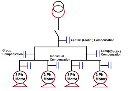
  • The reactive power supplied by the fixed capacitor bank is constant irrespective of any variations in the power factor and the load of the receivers. * These capacitor banks are switched on either manually (circuit breaker/ switch) or semi automatically by a remote-controlled contactor. * This arrangement uses one or more capacitor to provide a constant level of compensation. * These capacitors are applied at the terminals of inductive loads (mainly motors), at bus bars

Disadvantage:

  • Manual ON/OFF operation. * Not meet the require kvar under varying loads. * Penalty by electricity authority. * Power factor also varies as a function of the load requirements so it is difficult to maintain a consistent power factor by use of Fixed Compensation i.e. fixed capacitors. * Fixed Capacitor may provide leading power factor under light load conditions, Due to This result in over voltages, saturation of transformers, mal-operation of diesel generating sets, penalties by electric supply authorities.

Application:

  • Where the load factor is reasonably constant. * Electrical installations with constant load operating 24 hours a day * Reactive compensation of transformers. * Individual compensation of motors. * Where the kvar rating of the capacitors is less than, or equal to 15% of the supply transformer rating, a fixed value of compensation is appropriate. * Size of Fixed Capacitor bank Qc ≤ 15% kVA transformer

 (2) AUTOMATIC TYPE CAPACITOR BANKS

  • The reactive power supplied by the capacitor bank can be adjusted according to variations in the power factor and the load of the receivers. * These capacitor banks are made up of a combination of capacitor steps (step = capacitor + contactor) connected in parallel. Switching on and off of all or part of the capacitor bank is controlled by an integrated power factor controller. * The equipment is applied at points in an installation where the active-power or reactive power Variations are relatively large, for example: * At the bus bars of a main distribution switch-board, * At the terminals of a heavily-loaded feeder cable. * Where the kvar rating of the capacitors is less than, or equal to 15% of the supply transformer rating, a fixed value of compensation is appropriate. Above the 15% level, it is advisable to install an automatically-controlled bank of capacitors. * Control is usually provided by contactors. For compensation of highly fluctuating loads, fast and highly repetitive connection of capacitors is necessary, and static switches must be used.

Types of APFC:

  • Automatic Power Factor correction equipment is divided into three major categories: * (1)Standard = Capacitor + Fuse + Contactor + Controller * (2)De tuned = Capacitor + De tuning Reactor + Fuse + Contactor + Controller * (3)Filtered = Capacitor + Filter Reactor + Fuse + Contactor + Controller.

Advantage:

  • Consistently high power factor under fluctuating loads. * Prevention of leading power factor. * Eliminate power factor penalty. * Lower energy consumption by reducing losses. * Continuously sense and monitor load. * Automatically switch on/off relevant capacitors steps for consistent power factor. * Ensures easy user interface. * Automatically variation, without manual intervention, the compensation to suit the load requirements.

Application:

  • Variable load electrical installations. * Compensation of main LV distribution boards or major outgoing lines. * Above the 15% level, it is advisable to install an automatically-controlled bank of capacitors. * Size of Automatic Capacitor bank Qc > 15% kVA transformer.

Method Advantages Disadvantages Individual capacitors Most technically efficient, most flexible Higher installation & maintenance cost Fixed bank Most economical, fewer installations Less flexible, requires switches and/or circuit breakers Automatic bank Best for variable loads, prevents over voltages, low installation cost Higher equipment cost Combination Most practical for larger numbers of motors Least flexible

 TYPE OF CAPACITOR AS PER CONSTRUCTION:

 (1) STANDARD DUTY CAPACITOR:

  • Construction: Rectangular & Cylindrical(Resin filled / Resin coated-Dry) * Application: * Steady inductive load. * Non linear up to 10%. * For Agriculture duty.

(2) HEAVY-DUTY:

  • Construction: Rectangular & Cylindrical (Resin filled / Resin coated-Dry/oil/gas) * Application: * Suitable for fluctuating load. * Non linear up to 20%. * Suitable for APFC Panel. * Harmonic filtering

(3) LT Capacitor:

  • Application: * Suitable for fluctuating load. * Non linear up to 20%. * Suitable for APFC Panel & Harmonic filter application.

 SELECTING SIZE OF CAPACITOR BANK:

  • The size of the inductive load is large enough to select the minimum size of capacitors th…
F

Impact of Floating Neutral in Power Distribution

IMPACT OF FLOATING NEUTRAL IN POWER DISTRIBUTION

INTRODUCTION:

  • If The Neutral Conductor opens, Break or Loose at either its source side (Distribution Transformer, Generator or at Load side (Distribution Panel of Consumer), the distribution system’s neutral conductor will “float” or lose its reference ground Point. The floating neutral condition can cause voltages to float to a maximum of its Phase volts RMS relative to ground, subjecting to its unbalancing load Condition. * Floating Neutral conditions in the power network have different impact depending on the type of Supply, Type of installation and Load balancing in the Distribution. Broken Neutral or Loose Neutral would damage to the connected Load or Create hazardous Touch Voltage at equipment body. Here We are trying to understand the Floating Neutral Condition in T-T distribution System.

WHAT IS FLOATING NEUTRAL?

  • If the Star Point of Unbalanced Load is not joined to the Star Point of its Power Source (Distribution Transformer or Generator) then Phase voltage do not remain same across each phase but its vary according to the Unbalanced of the load. * As the Potential of such an isolated Star Point or Neutral Point is always changing and not fixed so it’s called Floating Neutral.

NORMAL POWER CONDITION & FLOATING NEUTRAL CONDITION

NORMAL POWER CONDITION:

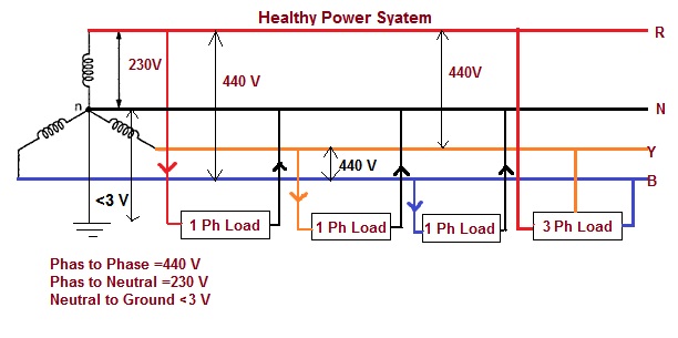
  • On 3-phase systems there is a tendency for the star-point and Phases to want to ‘balance out’ based on the ratio of leakage on each Phase to Earth. The star-point will remain close to 0V depending on the distribution of the load and subsequent leakage (higher load on a phase usually means higher leakage). * Three phase systems may or may not have a neutral wire. A neutral wire allows the three phase system to use a higher voltage while still supporting lower voltage single phase appliances. In high voltage distribution situations it is common not to have a neutral wire as the loads can simply be connected between phases (phase-phase connection).

  • 3 Phase 3 Wire System: * Three phases has properties that make it very desirable in electric power systems. Firstly the phase currents tend to cancel one another (summing to zero in the case of a linear balanced load). This makes it possible to eliminate the neutral conductor on some lines. Secondly power transfer into a linear balanced load is constant. * 3 Phase 4 Wire System for Mix Load: * Most domestic loads are single phase. Generally three phase power either does not enter domestic houses or it is split out at the main distribution board. * Kirchhoff’s Current Law states that the signed sum of the currents entering a node is zero. If the neutral point is the node, then, in a balanced system, one phase matches the other two phases, resulting in no current through neutral. Any imbalance of Load will result in a current flow on neutral, so that the sum of zero is maintained. * For instance, in a balanced system, current entering the neutral node from one Phase side is considered positive, and the current entering (actually leaving) the neutral node from the other side is considered negative. * This gets more complicated in three phase power, because now we have to consider phase angle, but the concept is exactly the same. If we are connected in Star connection with a neutral, then the neutral conductor will have zero current on it only if the three phases have the same current on each. If we do vector analysis on this, adding up sin(x), sin(x+120), and sin(x+240), we get zero. * The same thing happens when we are delta connected, without a neutral, but then the imbalance occurs out in the distribution system, beyond the service transformers, because the distribution system is generally a Star Connected. * The neutral should never be connected to a ground except at the point at the service where the neutral is initially grounded (At Distribution Transformer). This can set up the ground as a path for current to travel back to the service. Any break in the ground path would then expose a voltage potential. Grounding the neutral in a 3 phase system helps stabilize phase voltages. A non-grounded neutral is sometimes referred to as a “floating neutral” and has a few limited applications.

FLOATING NEUTRAL CONDITION:

  • Power flows in and out of customers’ premises from the distribution network, entering via the Phase and leaving via the neutral. If there is a break in the neutral return path electricity may then travel by a different path. Power flow entering in one Phase returns through remaining two phases. Neutral Point is not at ground Level but it Float up to Line Voltage. This situation can be very dangerous and customers may suffer serious electric shocks if they touch something where electricity is present.
F

Effects of High Voltage Transmission Lines on Humans and Plants

EFFECTS OF HIGH VOLTAGE TRANSMISSION LINES ON HUMANS AND PLANTS

 INTRODUCTION:

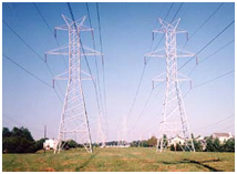
By increasing population of the world, towns are expanding, many buildings construct near high voltage overhead power transmission lines. The increase of power demand has increased the need for transmitting huge amount of power over long distances. Large transmission lines configurations with high voltage and current levels generate large values of electric and magnetic fields stresses which affect the human being and the nearby objects located at ground surfaces. This needs to be investigating the effects of electromagnetic fields near the transmission lines on human health.

The electricity system produces extremely low frequency electromagnetic field which comes under Non ionizing radiations which can cause health effects. Apart from human effect, the electrostatic coupling & electromagnetic interference of high voltage transmission lines have impact on plants and telecommunication equipments mainly operating in frequency range below UHF.

IS Power Line EMF safe? This is the controversy Discussion directly eludes on Government Regulation policy and Power Company. There are lots of supporting documents and research paper in favor and criticize this arguments.

WHAT IS THE ELECTRIC AND MAGNETIC FIELDS:

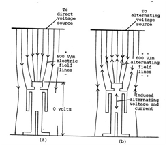
  • Electric and magnetic fields, often referred to as electromagnetic fields or EMF, occur naturally and as a result of the Power generation, Power Transmission, Power distribution and use of electric power. * EMF is fields of force and is created by electric voltage and current. They occur around electrical devices or whenever power lines are energized. * Electric fields are due to voltage so they are present in electrical appliances and cords whenever the electric cord to an appliance is plugged into an outlet (even if the appliance is turned off). * Electric fields (E) exist whenever a (+) or (-) electrical charge is present. They exert forces on other charges within the field. Any electrical wire that is charged will produce an electric field (i.e. Electric field produces charging of bodies, discharge currents, biological effects and sparks). This field exists even when there is no current flowing. The higher the voltage, the stronger is electric field at any given distance from the wire. * The strength of the electric field is typically measured in volts per meter (V/m) or in kilovolts per meter (kV/m). Electric fields are weakened by objects like trees, buildings, and vehicles. Burying power lines can eliminate human exposure to electric fields from this source. * Magnetic fields result from the motion of the electric charge or current, such as when there is current flowing through a power line or when an appliance is plugged in and turned on. Appliances which are plugged in but not turned on do not produce magnetic fields. * Magnetic field lines run in circles around the conductor (i.e. produces magnetic induction on objects and induced currents inside human and animal (or any other conducting) bodies causing possible health effects and a multitude of interference problems). The higher the current, the greater the strength of the magnetic field. * Magnetic fields are typically measured in tesla (T) or more commonly, in gauss (G) and milli gauss (mG). One tesla equals 10,000 gauss and one gauss equals 1,000 milli gauss. * The strength of an EMF decreases significantly with increasing distance from the source. * The Strength of an electric field is proportional to the voltage of the source. Thus, the electric fields beneath high voltage transmission lines far exceed those below the lower voltage distribution lines. The magnetic field strength, by contrast, is proportional to the current in the lines, so that a low voltage distribution line with a high current load may produce a magnetic field that is as high as those produced by some high voltage transmission lines. * In fact, electric distribution systems account for a far higher proportion of the population’s exposure to magnetic fields than the larger and more visible high voltage transmission lines. * Electrical field: the part of the EMF that can easily be shielded. * Magnetic field: part of the EMF that can penetrate stone, steel and human flesh. In fact, when it comes to magnetic fields, human flesh and bone has the same penetrability as air! * Both fields are invisible and perfectly silent: People who live in an area with electric power, some level of artificial EMF is surrounding them. * The magnetic field strength produced from a transmission line is proportional to: load current, phase to phase spacing, and the inverse square of the distance from the line. * Many previous works studied the effect of different parameters on the produced magnetic field such as: the distance from the line…
F

Analysis the Truth behind Household Power Savers

ANALYSIS THE TRUTH BEHIND HOUSEHOLD POWER SAVERS

INTRODUCTION:

  • A House hold power saving devices has recently received a lot of attention from both consumers and manufacturers. It is generally used in residential homes to save energy and to reduce electricity bills. It is a small device which is to be plugged in any of the AC sockets in the house (Mostly near Energy Meter). Moreover, some of the companies claim that their power savers save up to 40% of the energy. * Many people believe that the claims made by the power saver manufacturing companies are false. Almost all people who buy power savers do it to reduce their electricity bills. Many people who have used these power savers said that they could reduce their electricity bills with the devices; however the reduction was not as much as they had expected. Moreover, they could not figure out if the reduction in electricity bills was due to the power savers or because of their efforts to reduce their electrical usage. There have been several serious discussions about the genuineness of the device. In This Note, We will try to find the real truth behind these power savers which claim to save as much as 40% of energy.

WORKING PRINCIPLE OF POWER SAVER AS PER MANUFACTURE:

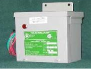
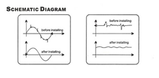
  • A Power Saver is a device which plugs in to power socket. Apparently just by keeping the device connected it will immediately reduce your power consumption. Typical claims are savings between 25% and 40%. * It is known that the electricity that comes to our homes is not stable in nature. There are many fluctuations, raise and falls, and surges/Spikes in this current. This unstable current cannot be used by any of the household appliances. Moreover, the fluctuating current wastes the electric current from the circuit by converting electrical energy into heat energy. This heat energy not only gets wasted to the atmosphere, but also harms the appliances and wiring circuit.

  • Power Saver stores the electricity inside of it using a system of capacitorsand they release it in a smoother way to normal without the spikes. The systems also automatically remove carbon from the circuit which also encourages a smoother electrical flow. This means that we will have less power spikes. More of the electricity flowing around circuit can be used to power appliances than before. * Basically it is claimed that Power savers work on the principle of surge protection technology. Power savers work on straightening this unstable electric current to provide a smooth and constant output. The fluctuation in voltage is unpredictable and cannot be controlled. However, the power savers utilize current fluctuation to provide a usable power by acting like a filter and allowing only smooth current to pass through the circuit. Power savers use capacitors for this purpose. When there is a surge of current in the circuit, the capacitor of the power saver stores the excess current and releases it when there is a sudden drop. Thus only smooth output current comes out of the device. * Moreover, a power saver also removes any type of carbon in the system, which facilitates further smoother flow. The main advantage of power savers is not that they provide a backup system in times of low current, but that it protects the household appliances. It is known that a sudden rise in the power can destroy the electrical appliance. Thus, the power saver not only protects the appliance but also increases its life. Moreover, they also reduce the energy consumption and thus the electricity bills. * The amount of power saved by a power saver depends on the number of appliances on the circuit. Also, the system takes at least a week to adapt itself fully to the circuit, before it starts showing its peak performance. The maximum amount of voltage savings will be seen in areas where in the current fluctuation is the highest.

HOUSE HOLD POWER SAVER SCAM REVIEW:

  • Power Factor Correction for residential customers (home owners) is a scam? At most, each unit is worth as an investment. Power factor correction does make sense for some commercial / industrial customers. * Many Companies promoting and advertise that their Power Saver unit are able to save domestic residential power consumption by employing an “active power factor correction” method on the supply line. The concept seems pretty impressive as the concept is true and legally accepted. But practically, we will find that it’s not feasible. * To support above statement First we need to understand three terms.
  1. Type of Electrical Load of House, 2. Basic Power Terminology (KW, KVA, KVAR). 3. Electrical Tariff method of Electricity Company for Household Consumer and Industrial Consumer.
  • There are basically two kinds of load that exists in…
F

Types of Neutral Earthing in Power Distribution Systems

TYPES OF NEUTRAL EARTHING IN POWER DISTRIBUTION

TYPES OF NEUTRAL EARTHING IN POWER DISTRIBUTION:

 INTRODUCTION:

  • In the early power systems were mainly Neutral ungrounded due to the fact that the first ground fault did not require the tripping of the system. An unscheduled shutdown on the first ground fault was particularly undesirable for continuous process industries. These power systems required ground detection systems, but locating the fault often proved difficult. Although achieving the initial goal, the ungrounded system provided no control of transient over-voltages. * A capacitive coupling exists between the system conductors and ground in a typical distribution system. As a result, this series resonant L-C circuit can create over-voltages well in excess of line-to-line voltage when subjected to repetitive re-strikes of one phase to ground. This in turn, reduces insulation life resulting in possible equipment failure. * Neutral grounding systems are similar to fuses in that they do nothing until something in the system goes wrong. Then, like fuses, they protect personnel and equipment from damage. Damage comes from two factors, how long the fault lasts and how large the fault current is. Ground relays trip breakers and limit how long a fault lasts and Neutral grounding resistors limit how large the fault current is.

 IMPORTANCE OF NEUTRAL GROUNDING:

  • There are many neutral grounding options available for both Low and Medium voltage power systems. The neutral points of transformers, generators and rotating machinery to the earth ground network provides a reference point of zero volts. This protective measure offers many advantages over an ungrounded system, like,
  1. Reduced magnitude of transient over voltages 2. Simplified ground fault location 3. Improved system and equipment fault protection 4. Reduced maintenance time and expense 5. Greater safety for personnel 6. Improved lightning protection 7. Reduction in frequency of faults.

METHOD OF NEUTRAL EARTHING:

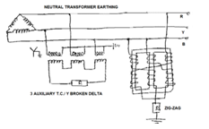
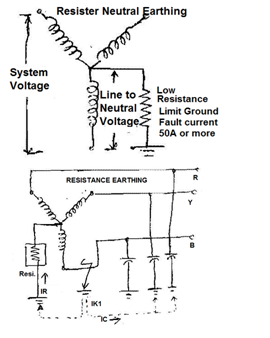
  • There are five methods for Neutral earthing.
  1. Unearthed Neutral System 2. Solid Neutral Earthed System. 3. Resistance Neutral Earthing System.Resonant Neutral Earthing System. 1. Low Resistance Earthing. 2. High Resistance Earthing. 4. Resonant Earthing System. 5. Earthing Transformer Earthing.

 (1) UNGROUNDED NEUTRAL SYSTEMS:

  • In ungrounded system there is no internal connection between the conductors and earth. However, as system, a capacitive coupling exists between the system conductors and the adjacent grounded surfaces. Consequently, the “ungrounded system” is, in reality, a “capacitive grounded system” by virtue of the distributed capacitance. * Under normal operating conditions, this distributed capacitance causes no problems. In fact, it is beneficial because it establishes, in effect, a neutral point for the system; As a result, the phase conductors are stressed at only line-to-neutral voltage above ground. * But problems can rise in ground fault conditions. A ground fault on one line results in full line-to-line voltage appearing throughout the system. Thus, a voltage 1.73 times the normal voltage is present on all insulation in the system. This situation can often cause failures in older motors and transformers, due to insulation breakdown.

  • Advantage:

  1. After the first ground fault, assuming it remains as a single fault, the circuit may continue in operation, permitting continued production until a convenient shut down for maintenance can be scheduled.
  • Disadvantages:
  1. The interaction between the faulted system and its distributed capacitance may cause transient over-voltages (several times normal) to appear from line to ground during normal switching of a circuit having a line-to ground fault (short). These over voltages may cause insulation failures at points other than the original fault. 2. A second fault on another phase may occur before the first fault can be cleared. This can result in very high line-to-line fault currents, equipment damage and disruption of both circuits. 3. The cost of equipment damage. 4. Complicate for locating fault(s), involving a tedious process of trial and error: first isolating the correct feeder, then the branch, and finally, the equipment at fault. The result is unnecessarily lengthy and expensive down downtime.

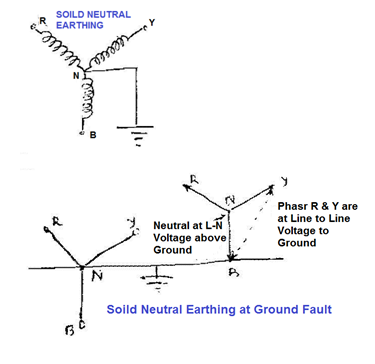
 (2) SOLIDLY NEUTRAL GROUNDED SYSTEMS:

  • Solidly grounded systems are usually used in low voltage applications at 600 volts or less. * In solidly grounded system, the neutral point is connected to earth. * Solidly Neutral Grounding slightly reduces the problem of transient over voltages found on the ungrounded system and provided path for the ground fault current is in the range of 25 to 100% of the system three phase fault current. However, if the reactance of the generator or…
F

Type of Electrical Power Distribution systems

TYPE OF ELECTRICAL POWER DISTRIBUTION SYSTEMS

TYPE OF ELECTRICAL POWER DISTRIBUTION SYSTEMS:

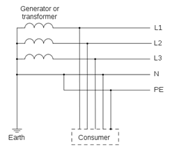
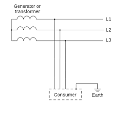
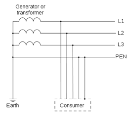
  • Electrical power is distribution either three wires or Four wires (3 wire for phases and 1 wire for Neutral). Voltage between Phase to Phase Called Line Voltage and Voltage between Phase and Neutral is Called Phase Voltage. * This Forth wire may or may not be distributed in Distribution System and Same way this neutral may or may not be earthed * Depending of this neutral condition (Earthed-not Earthed-access-not access) there are various type of earthing System. * The neutral may be directly connected to earth or connected through a resistor or a reactor. This system is called directly earthed or Earthed System. * When a connection has not been made between the neutral point and earth, we say that the neutral is unearthed. * In a network, the earthing system plays a very important role. When an insulation fault occurs or a phase is accidentally earthed, the values taken by the fault currents, the touch voltages and over voltages are closely linked to the type of neutral earthing connection. * A directly earthed neutral strongly limits over voltages but it causes very high fault currents, here as an unearthed neutral limits fault currents to very low values but encourages the occurrence of high over voltages. * In any installation, service continuity in the event of an insulation fault is also directly related to the earthing system. An unearthed neutral permits service continuity during an insulation fault. Contrary to this, a directly earthed neutral, or low impedance-earthed neutral, causes tripping as soon as the first insulation fault occurs. * The choice of earthing system in both low voltage and medium voltage networks depends on the type of installation as well as the type of network. It is also influenced by the type of loads and service continuity required. * The Main objectives of an earthing system are Provide an alternative path for the fault current to flow so that it will not endanger the user, Ensure that all exposed conductive parts do not reach a dangerous potential, Maintain the voltage at any part of an electrical system at a known value and prevent over current or excessive voltage on the appliances or equipment. * Different earthing systems are capable of carrying different amounts of over current. Since the amount of over current produced in different types of installation differs from each other, required type of earthing will also differ according to the type of installation. so in order to ensure that the installation goes with the existing earthing system or else to do any modification accordingly, we need to have a proper idea of the present earthing system. It would enhance the safety as well as the reliability * As per IEC 60364-3 There are three types of systems:

(1) Unearthed System:

  • IT System.

(2) Earthed System:

  • TT * TN (TN-S, TN-C, TN-C-S). * The first letter defines the neutral point in relation to earth:
  1. T = directly earthed neutral (from the French word Terre) 2. I =unearthed or high impedance-earthed neutral (e.g. 2,000 Ω)
  • The second letter defines the exposed conductive parts of the electrical installation in relation to earth:
  1. T =directly earthed exposed conductive parts 2. N =exposed conductive parts directly connected to the neutral conductor

 UNEARTHED SYSTEM:

 (1) IT SYSTEM UNEARTHED (HIGH IMPEDANCE EARTHED NEUTRAL)

  • First Letter I= the neutral is unearthed at Transformer or Generator side. * Second Letter T= Frame parts of the loads are interconnected and earthed at Load Side

  • is compulsory to install an over voltage limiter between the MV/LV transformer neutral point and earth.

  • If the neutral is not accessible, the overvoltage limiter is installed between a phase and earth. * It runs off external over voltages, transmitted by the transformer, to the earth and protects the low voltage network from a voltage increase due to flashover between the transformer’s medium voltage and low voltage windings.

Advantages:

  1. System providing the best service continuity during use. 2. When an insulation fault occurs, the short-circuit current is very low. 3. Higher operational safety only a capacitive current flows, which is caused by the system leakage capacitance if an earth fault occurs. 4. Better accident prevention the fault current is limited by the body impedance, earthing resistance and the high impedance of the earth fault loop.

Disadvantages:

  1. Requires presence of maintenance personnel to monitor and locate the first fault during use. 2. Requires a good level of network insulation (High leakage current must be supplied by insulating transformers). 3. Overvoltage limiters must be installed. 4. Requires all the installation’s exposed conductive parts to be …
F

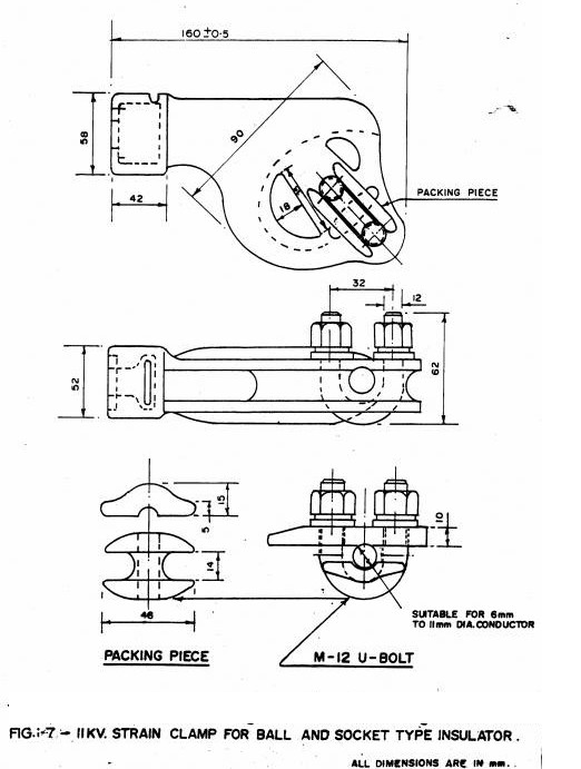
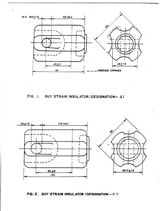
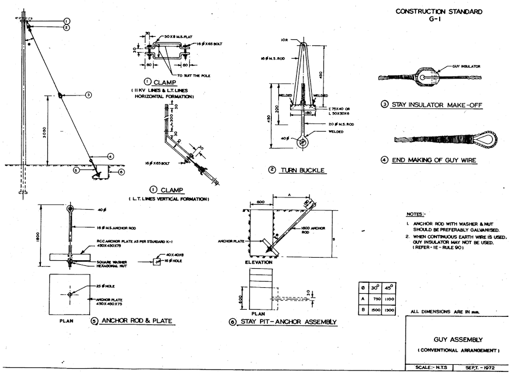
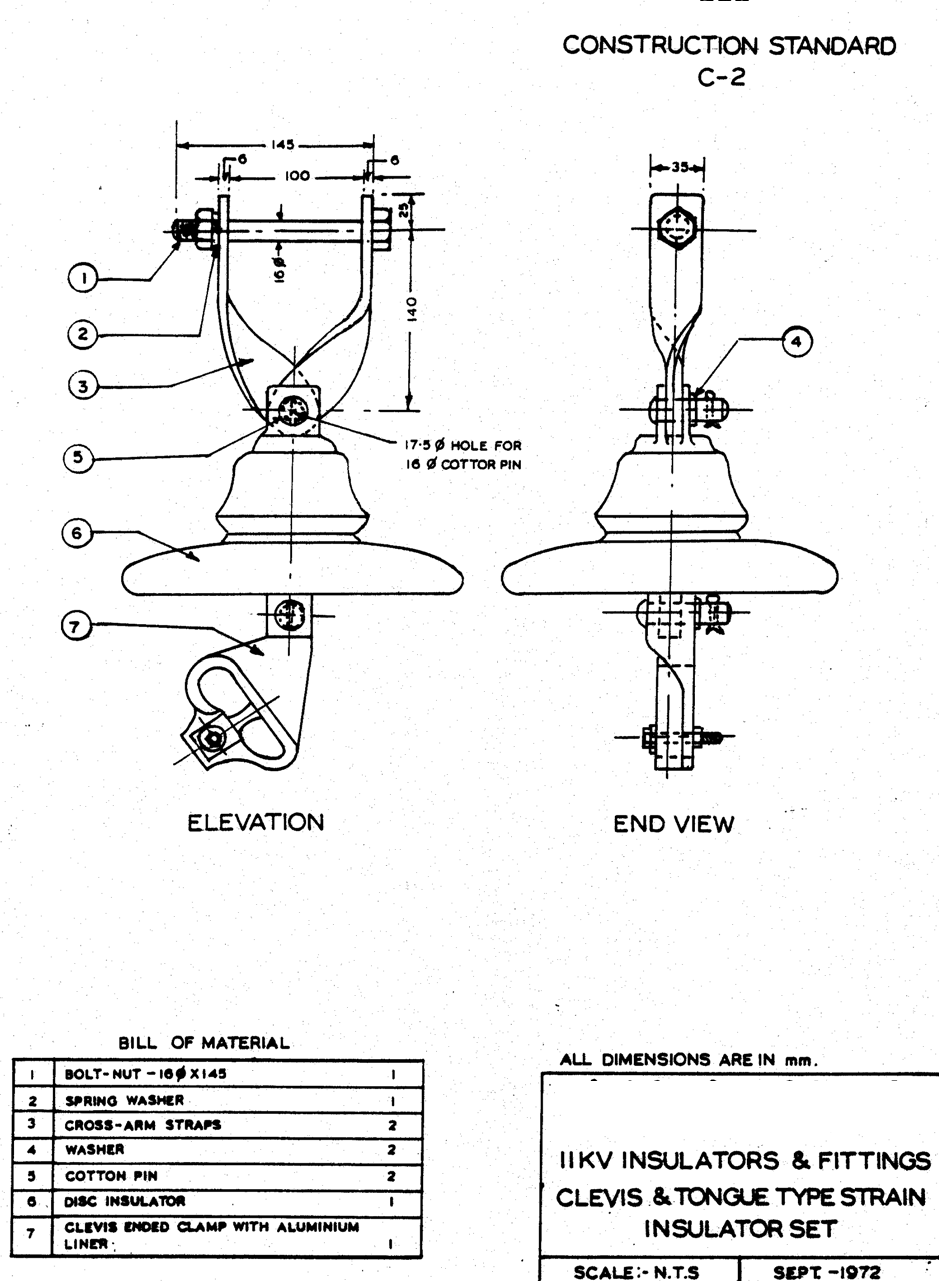
11KV/415V Overhead Line Specification as per REC

11KV/415V OVERHEAD LINE SPECIFICATION(REC)

11KV/415V OVER HEAD LINE’S SPECIFICATION AND INSTALLATION (REC):

 11KV LIGHTNING ARRESTER (IS: 3070 (PT-II)).

VOLTAGE RATING FOR LA:

  • The rated voltage of lightning arresters shall be 9 KV (rms). * This will be applicable to the effectively earthed 11 KV systems co-efficient of earth not exceeding 80 percent as per IS: 4004 with all the transformer neutrals directly earthed.

NORMAL DISCHARGE CURRENT RATING FOR LA:

  • The nominal discharge current rating of the lightning arresters shall be 5 KA.

TESTS FOR LA:

  • The following routine and type tests as laid down in IS : 3070 (Part-I) shall be carried out. * Routine Test: Dry Power frequency spark over test. * Type Tests (Confirmation) :
  1. Voltage withstand tests of arrester insulation. 2. Power frequency spark over test 3. Hundred percent 1.2/550 microsecond impulse spark over test 4. Front-of-wave impulse spark over test. 5. Residual voltage test. 6. Impulse current withstand test. 7. Operating duty test. 8. Temperature cycle test on porcelain housing. 9. Porosity test on porcelain components. 10. Galvanizing test on metal parts.

11 KV DROP-OUT FUSE CUTOUTS: (IS: 9385 (PART-I TO III).)

  • The distribution fuse cutouts shall be outdoor, open, drop-out expulsion type fuse cutouts suitable for installation in 50 Hz, 11 KV distribution system. * The rated voltage shall be 12 KV. * The rated current shall be 100 A.

RATED LIGHTING IMPULSE WITHSTANDS VOLTAGE FOR FUSE:

  • To earth and between poles 75 KV (Peak) * Across the isolating distance of fuse base 86 KV (Peak)

RATED ONE MINUTE POWER FREQUENCY WITHSTAND VOLTAGE (WET & DRY) FOR FUSE:

  • To earth and between poles 28 KV (rms) * Across the isolating distance 32 KV (rms)

TEMPERATURE RISE LIMIT FOR FUSE:

  • Copper contacts silver faced 650C * Terminals 500C * Metal parts acting as spring The temperature shall not reach such a value that Elasticity of the metal is changed

RATED BREAKING CAPACITY FOR FUSE:

  • The rated breaking capacity shall be 8 KA (Asymmetrical).

CONSTRUCTION DETAILS FOR FUSE:

  • The cutouts shall be of single vent type (downward) having a front connected fuse carrier suitable for angle mounting. * All ferrous parts shall be hot dip galvanized in accordance with the latest version of IS : 2632. Nuts and bolts shall conform to IS : 1364. Spring washers shall be electro-galvanized.

FUSE BASE TOP ASSEMBLY:

  • The top current carrying parts shall be made of a highly conductive copper alloy and the contact portion shall be silver plated for corrosion resistance and efficient current flow. * The contact shall have a socket cavity for latching and holding firmly the fuse carrier until the fault interruption is completed within the fuse. * The top assembly shall have an aluminum alloy terminal connector. The top assembly shall be robust enough to absorb bulk of the forces during the fuse carrier closing and opening operations and shall not over-stress the spring contact. It shall also prohibit accidental opening of the fuse carrier due to vibrations or impact.

FUSE BASE BOTTOM ASSEMBLY:

  • The conducting parts shall be made of high strength highly conductive copper alloy and the contact portion shall be silver plated for corrosion resistance and shall provide a low resistance current path from the bottom fuse carrier contacts to the bottom terminal connector.

FUSE CARRIER TOP ASSEMBLY:

  • The fuse carrier top contact shall have a solid replaceable cap made from highly conductive, anticorrosive copper alloy and the contact portion shall be silver plated to provide a low resistance current path from the Fuse Base Top Contact to the Fuse Link. * It shall make a firm contact with the button head of the fuse link and shall provide a protective enclosure to the fuse link to check spreading of arc during fault interruptions. * The fuse carrier shall be provided with a cast bronze opening eye (pull ring) suitable for operation with a hook stick from the ground level to pull-out or close-in the fuse carrier by manual operation.

FUSE CARRIER BOTTOM ASSEMBLY:

  • The fuse carrier bottom assembly shall be made of bronze castings with silver plating at the contact points to efficiently transfer current to fuse base. * It shall make smooth contact with the fuse base bottom assembly during closing operation. The bottom assembly shall have a lifting eye for the hook stick for removing or replacing the fuse carrier.

FUSE BASE (PORCELAIN):

  • The fuse base shall be a bird-proof, single unit porcelain insulator with a creepage distance (to earth) not less than 320 mm. The top and bottom assemblies as also the middle clamping hardware shall be either embedded in the porcelain insulator with sulphur cement or suitably clamped in position. * For embedded components, the pull out strength should be such as to result in breaking of the porcelain before …

Power Quality

POWER QUALITY

Power Quality:

  • In the present scenario of power utilization and consumption, the importance of power quality is vital for a continuous and effective power supply. The features of power quality play a major role in the effective power utilization along with the control & improvement measures for various factors affecting it. * Power quality is defined as the ability of a system to
  1. Deliver electric power service of sufficiently high quality so that the end-use equipment will operate within their design specifications and

  2. It should be of sufficient reliability so that the operator of end-use equipment will be continuous.

  • In other words it may be defined as the concept of powering, grounding and protecting electric equipment in a manner that is suitable to the operation of that equipment.

Why is it a concern?

  • Power Quality has been a problem since the conception of electricity, but only over the last 2 decades has it gotten considerable attention with the introduction of large numbers of computers & microprocessors in business and homes; and the network revolution and ever increasing equipment capability and speed. * There are various factors that really make us think about it.
  1. Power quality problems can cause equipment malfunctions, excessive wear or premature, failure of equipment, increased costs, increased maintenance, repair time and expense & outside consultant expense.

  2. Electronic equipments are more sensitive to minor fluctuations. We rely on the equipment more and have higher expectations. New electronic devices are more sensitive than the equipment being replaced as well.

Power Quality Affecting Factor:

  • Many electronic devices are susceptible to power quality problems and a source of power quality problems. Some of the important concerns are
  1. Waveform Distortions like Harmonics

  2. Transients

  3. Voltage Fluctuations such as Voltage Sags & Swells

  4. Interruptions e.g. Outages & Blinks

  5. Waveform Distortions -Harmonics

  • Due to substantial increase of non-linear loads such as the use of power electronics circuits and devices, the ac power system suffers from harmonic problems. In general, we may classify sources of harmonics into three categories i.e.
  1. Domestic loads,

  2. Industrial loads,

  3. Control devices.

  • A harmonic is “a sinusoidal component of a periodic wave or quantity having a frequency i.e. an integral multiple of fundamental frequency”. Pure or clean power is referred as those without harmonics. But this only exists in laboratories. The frequencies of the harmonics are different, depending on the fundamental frequency. Due to high harmonic voltage and/or current levels, there are a number of equipments that can have miss operation or failures. * The main sources of harmonic current are the phase angle controlled rectifiers and inverters. * Although the applied voltage to a transformer is sinusoidal, the magnetization current related to the flux through the lamination magnetization curve is non-sinusoidal. These harmonics have their maximum effect during the first hours of the day (when the system is lightly loaded and the voltage is higher).
  1. Transients
  • Transients occur in Distribution System due to factors like Lightning, Switching Operations, and Fault Clearing/Breaker Operations etc. The various causes of transients in Customer System are Lightning, Arcing Devices, Starting & Stopping Motors, Breaker Operations, and Capacitor Switching etc.
  1. Voltage Fluctuations such as Voltage Sags & Swells
  • In Sags, Voltage falls below 90% of normal but stays above 10% of normal for any amount of time. In Swells, Voltage rises above 110% of normal but below 180% of normal for any amount of time. If it’s long enough, you notice lights dimming or getting brighter. Sags are much more common than swells.
  1. Interruptions e.g. Outages and Blinks
  • Interruptions may be defined as the interrupts that hampers the normal flow of voltage or power quality. When Voltage falls below 10% of normal circuit voltage for any length of time the power supply is off. The outages can be of microseconds to hours or days. When interruptions occur there is a chance of blinking as well.

Control & improvement of The System:

  • In order to overcome the various affecting factors, we need to implement some control and improvement measures. They are discussed as follows:
  1. Harmonics
  • Several techniques are adopted to minimize harmonic effects like increasing pulse number, passive filters and active filters. By use of these techniques we get higher pulse, trap the harmonics and convert the non-linear ac line current into a sinusoidal wave respectively. * Power quality analysis is really a matter of concern as it is quite evident how important supply of power is especially in organizations where critical loads need continuous supply of clean power and…