Site logo
Electrical Engineering Academy
Cover image
F

Ferranti Effect in Transmission Line

FERRANTI EFFECT

WHAT IS FERRANTI EFFECT

  • A long transmission line draws a substantial quantity of charging current. If such a line is open circuited or very lightly loaded at the receiving end, Receiving end voltage being greater than sending end voltage in a transmission line is known as Ferranti effect. All electrical loads are inductive in nature and hence they consume lot of reactive power from the transmission lines. Hence there is voltage drop in the lines. Capacitors which supply reactive power are connected parallel to the transmission lines at the receiving end so as to compensate the reactive power consumed by the inductive loads. * As the inductive load increases more of the capacitors are connected parallel via electronic switching. Thus reactive power consumed by inductive loads is supplied by the capacitors thereby reducing the consumption of reactive power from transmission line. However when the inductive loads are switched off the capacitors may still be in ON condition. The reactive power supplied by the capacitors adds on to the transmission lines due to the absence of inductance. As a result voltage at the receiving end or consumer end increases and is more than the voltage at the supply end. This is known as Ferranti effect.

WHY DOES VOLTAGE RISE ON A LONG, UNLOADED TRANSMISSION LINE?

  • The Ferranti Effect occurs when current drawn by the distributed capacitance of the transmission line itself is greater than the current associated with the load at the receiving end of the line. Therefore, the Ferranti effect tends to be a bigger problem on lightly loaded lines, and especially on underground cable circuits where the shunt capacitance is greater than with a corresponding overhead line. This effect is due to the voltage drop across the line inductance (due to charging current) being in phase with the sending end voltages. As this voltage drop affects the sending end voltage, the receiving end voltage becomes greater. The Ferranti Effect will be more pronounced the longer the line and the higher the voltage applied. * The Ferranti Effect is not a problem with lines that are loaded because line capacitive effect is constant independent of load, while inductance will vary with load. As inductive load is added, the VAR generated by the line capacitance is consumed by the load.

HOW TO REDUCE FERRANTI EFFECT:

SHUNT REACTORS AND SERIES CAPACITORS:

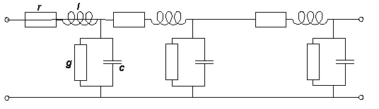
  • The need for large shunt reactors appeared when long power transmission lines for system voltage 220 kV & higher were built. The characteristic parameters of a line are the series inductance (due to the magnetic field around the conductors) & the shunt capacitance (due to the electrostatic field to earth).

  • Both the inductance & the capacitance are distributed along the length of the line. So are the series resistance and the admittance to earth. When the line is loaded, there is a voltage drop along the line due to the series inductance and the series resistance. When the line is energized but not loaded or only loaded with a small current, there is a voltage rise along the line (the Ferranti-effect) * In this situation, the capacitance to earth draws a current through the line, which may be capacitive. When a capacitive current flows through the line inductance there will be a voltage rise along the line. * To stabilize the line voltage the line inductance can be compensated by means of series capacitors and the line capacitance to earth by shunt reactors. Series capacitors are placed at different places along the line while shunt reactors are often installed in the stations at the ends of line. In this way, the voltage difference between the ends of the line is reduced both in amplitude and in phase angle. * Shunt reactors may also be connected to the power system at junctures where several lines meet or to tertiary windings of transformers. * Transmission cables have much higher capacitance to earth than overhead lines. Long submarine cables for system voltages of 100 KV and more need shunt reactors. The same goes for large urban networks to prevent excessive voltage rise when a high load suddenly falls out due to a failure. * Shunt reactors contain the same components as power transformers, like windings, core, tank, bushings and insulating oil and are suitable for manufacturing in transformer factories. The main difference is the reactor core limbs, which have non-magnetic gaps inserted between packets of core steel. * 3-phase reactors can also be made. These may have 3- or -5-limbed cores. In a 3-limbed core there is strong magnetic coupling between the three phases, while in a 5-limbed core the phases are magnetically independent due to the enclosing magnetic frame formed by the two yokes and the two unwound side-limbs. * The neutral of shunt reactor may be …

What is Corona Effect in Transmission Line

WHAT IS CORONA EFFECT

INTRODUCTION:

One of the phenomena associated with all energized electrical devices, including high-voltage transmission lines, is corona. The localized electric field near a conductor can be sufficiently concentrated to ionize air close to the conductors. This can result in a partial discharge of electrical energy called a corona discharge, or corona.

WHAT IS CORONA?

  • Electric transmission lines can generate a small amount of sound energy as a result of corona. * Corona is a phenomenon associated with all transmission lines. Under certain conditions, the localized electric field near energized components and conductors can produce a tiny electric discharge or corona that causes the surrounding air molecules to ionize, or undergo a slight localized change of electric charge. * Utility companies try to reduce the amount of corona because in addition to the low levels of noise that result, corona is a power loss, and in extreme cases, it can damage system components over time. * Corona occurs on all types of transmission lines, but it becomes more noticeable at higher voltages (345 kV and higher). Under fair weather conditions, the audible noise from corona is minor and rarely noticed. * During wet and humid conditions, water drops collect on the conductors and increase corona activity. Under these conditions, a crackling or humming sound may be heard in the immediate vicinity of the line. * Corona results in a power loss. Power losses like corona result in operating inefficiencies and increase the cost of service for all ratepayers; a major concern in transmission line design is the reduction of losses.

 SOURCE OF CORONA:

  • The amount of corona produced by a transmission line is a function of the voltage of the line, the diameter of the conductors, the locations of the conductors in relation to each other, the elevation of the line above sea level, the condition of the conductors and hardware, and the local weather conditions. Power flow does not affect the amount of corona produced by a transmission line. * The electric field gradient is greatest at the surface of the conductor. Large-diameter conductors have lower electric field gradients at the conductor surface and, hence, lower corona than smaller conductors, everything else being equal. The conductors chosen for the Calumet to the line were selected to have large diameters and to utilize a two conductor bundle. This reduces the potential to create audible noise. * Irregularities (such as nicks and scrapes on the conductor surface or sharp edges on suspension hardware) concentrate the electric field at these locations and thus increase the electric field gradient and the resulting corona at these spots. Similarly, foreign objects on the conductor surface, such as dust or insects, can cause irregularities on the surface that are a source for corona. * Corona also increases at higher elevations where the density of the atmosphere is less than at sea level. Audible noise will vary with elevation. An increase in 1000 feet of elevation will result in an increase in audible noise of approximately 1 dB (A). Audible noise at 5000 feet in elevation will 5 dB (A) higher than the same audible noise at sea level, all other things being equal. The new Calumet to Comanche 345 kV double circuit line was modeled with an elevation of 6000 feet. * Raindrops, snow, fog, hoarfrost, and condensation accumulated on the conductor surface are also sources of surface irregularities that can increase corona. During fair weather, the number of these condensed water droplets or ice crystals is usually small and the corona effect is also small. * However, during wet weather, the number of these sources increases (for instance due to rain drops standing on the conductor) and corona effects are therefore greater. * During wet or foul weather conditions, the conductor will produce the greatest amount of corona noise. However, during heavy rain the noise generated by the falling rain drops hitting the ground will typically be greater than the noise generated by corona and thus will mask the audible noise from the transmission line. * Corona produced on a transmission line can be reduced by the design of the transmission line and the selection of hardware and conductors used for the construction of the line. For instance the use of conductor hangers that have rounded rather than sharp edges and no protruding bolts with sharp edges will reduce corona. The conductors themselves can be made with larger diameters and handled so that they have smooth surfaces without nicks or burrs or scrapes in the conductor strands. The transmission lines proposed here are designed to reduce corona generation.

 TYPES OF CORONA:

There are three types of corona.

  • A glow discharge occurs at a gradient of approximately 20 kV rms/cm. Glow discharge is a light glow off sharp p…

How Reactive Power helpful to maintain a System Healthy

IMPORTANCE OF REACTIVE POWER FOR SYSTEM

INTRODUCTION:

  • We always in practice to reduce reactive power to improve system efficiency .This are acceptable at some level. If system is purely resistively or capacitance it make cause some problem in Electrical system. Alternating systems supply or consume two kind of power: real power and reactive power. * Real power accomplishes useful work while reactive power supports the voltage that must be controlled for system reliability. Reactive power has a profound effect on the security of power systems because it affects voltages throughout the system. * Find important discussion regarding importance about Reactive Power and how it is useful to maintain System voltage healthy

 IMPORTANCE OF REACTIVE POWER:

  • Voltage control in an electrical power system is important for proper operation for electrical power equipment to prevent damage such as overheating of generators and motors, to reduce transmission losses and to maintain the ability of the system to withstand and prevent voltage collapse. * Decreasing reactive power causing voltage to fall while increasing it causing voltage to rise. A voltage collapse may be occurs when the system try to serve much more load than the voltage can support. * When reactive power supply lower voltage, as voltage drops current must increase to maintain power supplied, causing system to consume more reactive power and the voltage drops further . If the current increase too much, transmission lines go off line, overloading other lines and potentially causing cascading failures. * If the voltage drops too low, some generators will disconnect automatically to protect themselves. Voltage collapse occurs when an increase in load or less generation or transmission facilities causes dropping voltage, which causes a further reduction in reactive power from capacitor and line charging, and still there further voltage reductions. If voltage reduction continues, these will cause additional elements to trip, leading further reduction in voltage and loss of the load. The result in these entire progressive and uncontrollable declines in voltage is that the system unable to provide the reactive power required supplying the reactive power demands

 NECESSARY TO CONTROL OF VOLTAGE AND REACTIVE POWER:

  • Voltage control and reactive power management are two aspects of a single activity that both supports reliability and facilitates commercial transactions across transmission networks. * On an alternating current (AC) power system, voltage is controlled by managing production and absorption of reactive power. * There are three reasons why it is necessary to manage reactive power and control voltage. * First, both customer and power system equipment are designed to operate within a range of voltages, usually within±5% of the nominal voltage. At low voltages, many types of equipment perform poorly, light bulbs provide less illumination, induction motors can overheat and be damaged, and some electronic equipment will not operate at. High voltages can damage equipment and shorten their lifetimes. * Second, reactive power consumes transmission and generation resources. To maximize the amount of real power that can be transferred across a congested transmission interface, reactive power flows must be minimized. Similarly, reactive power production can limit a generator’s real power capability. * Third, moving reactive power on the transmission system incurs real power losses. Both capacity and energy must be supplied to replace these losses. * Voltage control is complicated by two additional factors. * First, the transmission system itself is a nonlinear consumer of reactive power, depending on system loading. At very light loading the system generates reactive power that must be absorbed, while at heavy loading the system consumes a large amount of reactive power that must be replaced. The system’s reactive power requirements also depend on the generation and transmission configuration. * Consequently, system reactive requirements vary in time as load levels and load and generation patterns change. The bulk power system is composed of many pieces of equipment, any one of which can fail at any time. Therefore, the system is designed to withstand the loss of any single piece of equipment and to continue operating without impacting any customers. That is, the system is designed to withstand a single contingency. The loss of a generator or a major transmission line can have the compounding effect of reducing the reactive supply and, at the same time, reconfiguring flows such that the system is consuming additional reactive power. * At least a portion of the reactive supply must be capable of responding quickly to changing reactive power demands and to maintain acceptable voltages throughout the system. Thus, just as an electrical system requires real powe…
F

Types of Overhead Conductors

OVERHEAD CONDUCTORS

TYPES OF OVERHEAD CONDUCTORS

PROPERTIES OF OVERHEAD BARE CONDUCTORS:

Current Carrying Capacity

  • Strength * Weight * Diameter * Corrosion Resistance * Creep Rate * Thermal Coefficient of Expansion * Fatigue Strength * Operating Temperature * Short Circuit Current/Temperature * Thermal Stability * Cost

CATEGORIES OF OVERHEAD CONDUCTORS:

Homogeneous Conductors:

  • Copper * AAC( All Aluminum Conductor) * AAAC (All Aluminum Alloy Conductor) * The core consists of a single strand identical to the outer strands. Since all the strands are the same diameter, one can show that the innermost layer always consists of 6 strands, the second layer of 12 strands, etc., making conductors having 1, 7, 19, 37, 61, 91, or 128 strands.

Non Homogeneous Conductors:

  • ACAR (Aluminum Conductor Alloy Reinforced) * ACSR (Aluminum Conductor Steel Reinforced) * ACSS (Aluminum Conductor Steel Supported) * AACSR (Aluminum Alloy Conductor Steel Reinforced. * the strands in the core may or may not be of the same diameter. In a 30/7 * ACSR conductor the aluminum and steel strands are of the same diameter. In a 30/19 * ACSR they are not. Within the core or within the outer layers, however, the number of strands always increases by 6 in each succeeding layer. Thus, in 26/7 ACSR, the number of layers in the inner layer of aluminum is 10 and in the outer layer 16

CATEGORIES OF OVERHEAD CONDUCTORS

  • VR (Vibration Resistance) * Non-Specular * ACSR / SD• (Self Damping)

CHOICES OF OVERHEAD DEPEND UPON:

Power Delivery Requirements

  • Current Carrying Capacity * Electrical Losses

Line Design Requirements

  • Distances to be Spanned * Sag and Clearance Requirements

Environmental Considerations

  • Ice and Wind Loading * Ambient Temperatures

(1) AAC (ALL ALUMINUM CONDUCTORS)

  • AAC is made up of one or more strands of hard drawn 1350 Aluminum Alloy. * AAC has had limited use in transmission lines and rural distribution because of the long spans utilized. * Good Conductivity -61.2% IACS * Good Corrosion Resistance * High Conductivity to Weight Ratio. * Moderate Strength

Typical Application

  • Short spans where maximum current transfer is required. * The excellent corrosion resistance of aluminum has made AAC a conductor of choice in coastal areas. * Because of its relatively poor strength-to-weight ratio, AAC has seen extensive use in urban areas where spans are usually short but high conductivity is required. * These conductors are used in low, medium and high voltage overhead lines.

(2) AAAC (ALL ALUMINUM ALLOY CONDUCTORS)

  • AAAC are made out of high strength Aluminum-Magnesium-Silicon alloy. * AAAC with different variants of electrical grade Alloys type 6101 and 6201. * These conductors are designed to get better strength to weight ratio and offers improved electrical characteristics, excellent sag-tension characteristics and superior corrosion resistance when compared with ACSR. * Equivalent aluminum alloy conductors have approximately the same ampacity and strength as their ACSR counterparts with a much improved strength-to-weight ratio, and also exhibit substantially better electrical loss characteristics than their equivalent single layer ACSR constructions. The thermal coefficient of expansion is greater than that of ACSR. * As compared to conventional ACSR, lighter weight, comparable strength & current carrying capacity, lower electrical losses and superior corrosion resistance have given AAAC a wide acceptance in the distribution and transmission lines.

Features

  • High strength to weight ratio * Better sag characteristics * Improved electrical properties * Excellent resistance to corrosion * Specifications * Higher Tensile Strength * Excellent Corrosion Resistance * Good Strength to Weight Ratio * Lower Electrical Losses * Moderate Conductivity –52.5% IACS

Typical Application

  • Transmission and Distribution applications in corrosive environments, ACSR replacement.

(3) ACAR (ALUMINUM CONDUCTOR AL. ALLOY REINFORCED)

  • Aluminum Conductor Alloy Reinforced (ACAR) is formed by concentrically stranded Wires of Aluminum 1350 on high strength Aluminum-Magnesium-Silicon (AlMgSi) Alloy core. * The number of wires of Aluminum 1350 & AlMgSi alloy depends on the cable design. * Even though the general design comprises a stranded core of AlMgSi alloy strands, in certain cable constructions the wires of AlMgSi Alloy strands can be distributed in layers throughout the Aluminum 1350 strands. * ACAR has got a better mechanical and electrical properties as compared to an equivalent conductors of ACSR,AAC or AAAC. * A very good balance between the mechanical and electrical properties therefore makes ACAR the best choice where the ampacity , strength , and light weig…

Guideline to Design Electrical Network for Building / Small Area.

GUIDELINE TO DESIGN ELECTRICAL NETWORK FOR BUILDING / SMALL AREA.

 GUIDELINE TO DESIGN ELECTRICAL NETWORK FOR BUILDING / SMALL AREA.

 (1) CALCULATE ELECTRICAL LOAD:

  • Find out built up area in Sqft.of per flat per House/Dwelling unit. * Multiply area in Sqft. by Load/Sqft according to following Table

Type of Load Load/Sqft Industrial 100 Watt/Sqft Commercial 30 Watt/Sqft Domestic 15 Watt/Sqft

  • Apply the diversity factor and Compute the load of all dwelling units in the area.

Type of Load Diversity Factor Industrial 0.5 Commercial 0.8 Domestic 0.4

  • Add the load of common services such as Auditorium, Street Lights, Lifts and Water Pumps etc. For simplicity purpose 0.5kW/dwelling units may be considered as common load. * Compute the “Total Load” of the area by adding load observed at above. * Apply the power factor of 0.8 to determine the load in kVA. * Compute the Load in kVA= “Total Load”/0.8 * Take transformer loading of 65% considering the network arrangement Ring Main Circuit.

 (2) DECIDE VOLTAGE GRADE FOR ELECTRICAL LOAD:

  • If load is equal to or more than 2.50MVA, the area shall be fed through 33kV feeder. For such loads, the land space for 33/11kV Sub-station shall have to be allocated by builder / Society/ Authority. * For load between 1 MVA to 2.5MVA, dedicated 11kV feeder shall be preferred. * For load below 1 MVA, existing 11kV feed can be tapped through VCB or RMU.

(3) DECIDE SIZE OF TRANSFORMER:

  • Select T.C Size of 25 KVA,63 KVA,100 KVA,200 KVA or 400 KVA according to your Load. * The maximum capacity of distribution transformer acceptable is 400 kVA as a standard capacity. * Only two-no of transformer at one location shall be acceptable. If there is more number of transformers HT shall be required to extend using underground cables to locate additional transformer.

(4) RMU / LT PANEL:

  • Either VCB or Ring Main Circuit shall be used to control transformers. There cables should have metering arrangement at 11kV. The protection system at incoming supply shall be using numerical relays. * On LT side of transformer, LT main feeder pillar shall be provided. The Incoming shall be protected by MCCB/SFU. * The distribution pillar-box shall be connected into Ring Main Unit. * The incomer of distribution pillar shall have MCCB / SFU. The outgoing shall have HRC fuses.

(5) THE LT CABLES FROM T.C TO LT PANEL / MAIN FEEDER PILLAR:

  • Decide Size of LT Cable from T.C to LT Panel as per following Table.

Transformer Size

Cable

630kVA transformers 2 no x 1C x 630 Sq mm, Al, XLPE Cable 400kVA transformers 1 no x 1C x 630 Sq mm, Al, XLPE 250kVA transformers 3 ½ C x 400 Sq mm, Al, XLPE 160kVA transformers 3 ½ C x 300 Sq mm, Al, XLPE 100kVA transformers 3 ½ C x 150 Sq mm, Al, XLPE

(6) CONSIDERING VARIOUS FACTORS & LENGTH OF CABLE:

  • The factors for cable loading shall be taken as 70%. * The factor for multiplicity of cables from same cable trench shall be 80%. * The suggested maximum length of LT cable feeder shall be 250 Mtrs. * The LT cables shall be connected in ring main circuit. * The load on sub-feeder pillar shall be restricted to 150kW.

(7) LT CABLES FROM MAIN FEEDER PILLARS TO DISTRIBUTION PILLAR BOXES:

Load on distribution pillar

LT Cable Size Up to 50kW 3 ½ C x 150 sqmm, AL, XLPE Up to 100kW 3 ½ C x 300 sqmm, AL, XLPE Up to 150 kW 3 ½ C x 400sqmm, AL, XLPE

(8) CALCULATE VOLTAGE DROP AND T&D LOSSES:

  • The entire system has to be designed for a voltage drop of 2.0% from11kV Side of transformer to metering equipment at end consumer premises. * The entire system has to be designed for T&D losses of service maximum 2.0% from 11kV to end consumer meter including of service cable.

Ref:

  1. NPC Limited. 2. Electrical code.

Effects of unbalanced Electrical Load (Part:2)

EFFECTS OF UNBALANCED ELECTRICAL LOAD (PART:2)

  • HARMONICS IN SYSTEM BY UPS:

  • UPS or inverter supplies also perform with poor efficiency and inject more harmonic currents in case of unbalances in the system

  • DECREASE LIFE CYCLE OF EQUIPMENT:

  • Unbalanced Voltage increase I2R Losses which increase Temperature. High temperatures, exceeding the rated value of a device, will directly decrease the life cycle of the device and speed up the replacement cycle for the device, and significantly increase the costs of operation and maintenance.

  • RELAY MALFUNCTION

  • Unbalanced Voltage flows Negative and Unbalanced Voltage of Voltage or Current. * The high zero-sequence current in consequence of voltage imbalance may bring about malfunctions of relay operation or make the ground relay less sensitive. That may result in serious safety problems in the system.

  • INACCURATE MEASUREMENT

  • Negative and zero-sequence components of voltages or currents will give rise to inaccurate measurements in many kinds of meters. * The imprecise measured values might affect the suitability of settings and coordination of relay protection systems and the correctness of decisions by some automated functions of the system.

  • DECREASE CAPACITY OF TRANSFORMERS, CABLES AND LINES

  • The capacity of transformers, cables and lines is reduced due to negative sequence components. The operational limit is determined by the RMS rating of the total current, due to ‘useless’ non-direct sequence currents the capacity of equipment is decrease.

  • INCREASE DISTRIBUTION LOSSES

  • Distribution network losses can vary significantly depending on the load unbalance. * Unbalance load increase I2R Losses of distribution Lines.

  • INCREASE ENERGY BILL BY INCREASING MAXIMUM DEMAND

  • Unbalanced Load increase maximum Demand of Electrical supply which is significantly effects on energy bill. By load balancing we can reduce energy bill. * For Energy Consumption Energy Supply Company does not charge on kVA but on kW for Residential customers. This means that they are charged for the “actual” energy used and not charged for the “total” energy supplied. Thus the power factor and Maximum Demand do not impact residential customers. * But Commercial, Industrial and H.T Connection charged by its maximum demand . We have to specify the maximum “demand“(in kVA) at the time of connection. During the month if you exceed your maximum “demand” you have to pay penalty (or extra price) for the same. That is the MDI penalty that appears on electricity bills. * Let’s assume That Two Company has same approved load of 40 KW and runs 30KW for 100 hours. * Electricity charge = 65 Rs per kWh * Demand charge = 210Rs per kW * Example 1: Company A runs a 30 KW loads continuously for 100 hours but It’s Maximum Demand is 50KW * 30 KW x 100 hours = 3,000 KWh * Energy Consumption Charge =3000×65=195000Rs * Demand difference = 50 KW-40KW=10KW * Demand Charges = 10X210=2100Rs * Total Bill: 195000+2100=197100Rs * Example 2: Company A runs a 30 KW loads continuously for 100 hours but It’s Maximum Demand is 40W * 30 KW x 100 hours = 3,000 KWh * Energy Consumption Charge =3000×65=195000Rs * Demand difference = 40 KW-40KW=0KW * Demand Charges = 0X210=00Rs * Total Bill: 195000+0=195000Rs

  • FAILURE OF TRANSFORMER

  • Three-phase voltage with high unbalanced may cause the flux inside the transformer core to be asymmetrical. * This asymmetrical flux will cause extra core loss, raise the winding temperature and may even cause transformer failure in a severe case. * Ideally any distribution transformer gives best performance at 50% loading and every electrical distribution system is designed for it. But in case of unbalance the loading goes over 50% as the equipments draw more current. * The efficiency of transformer under different loading conditions * Full Load- 98.1% * Half Load- 98.64% * Unbalanced loads- 96.5% * For a distribution transformer of 200KVA rating, the eddy currents accounts for 200W but in case of 5% voltage unbalance they can rise up to 720W.

  • BAD / LOOSE CONNECTION OF NEUTRAL WIRE

  • In balance Load condition Bad connection of Neutral wire does not make more impact on distribution System but in unbalance load condition such type of Bad neutral connection make worse impact on distribution. * The Three Phase power supplies a small a three-floor building. Each floor of this three-floor building is serviced by a single-phase feeder with a different phase. That is the first, second and third floor are serviced by phase R, Y and B. The external lighting load is connected only on R Phase. * The supply transformer is rated at 150 kVA and connected delta-grounded wye to provide for 430/220 V three-phase four-wire service. * This Transformer has a loose or Bad Neutral connection with the earth. * The transformer delivers a load of 35 kVA at 220 V with 0.9 power factor la…

Cover image
F

Effects of unbalanced Electrical Load (Part:1)

EFFECTS OF UNBALANCED ELECTRICAL LOAD (PART:1)

INTRODUCTION:

  • Generally, three phase balance is the ideal situation for a power system and quality of delivered Electrical Power. However Voltage unbalance may makes worse effect on Power quality of Electrical Power at distribution level. * The voltages are quite well balanced at the generator and transmission levels. but the voltages at the utilization level can become unbalanced due to the unequal system impedances, the unequal distribution of single phase loads, asymmetrical three-phase equipment and devices (such as three-phase transformers with open star-open delta connections), unbalanced faults, bad connections to electrical connectors. * An excessive level of voltage unbalance can have serious impacts on power quality. In the system the level of current unbalance is several times the level of voltage unbalance. Such an unbalance in the line currents can lead to excessive line losses, losses in the stator and rotor of Motor Malfunctioning of Relay, unsymmetrical measuring of Meters. Voltage unbalance also has an impact on ac variable speed drive systems where the front end converter consists of three-phase rectifier systems * Phase balancing is very important and usable to reduce distribution feeder losses and Improve system stability and security

WHAT IS UNBALANCE VOLTAGE

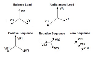
  • Any deviation in voltage and current waveform from perfect sinusoidal, in terms of magnitude or phase shift is termed as unbalance * In ideal conditions the phases of power supply are 120 degree apart in terms of phase angle and magnitude of their peaks should be same. On distribution level, the load imperfections cause current unbalance which travel to transformer and cause unbalance in the three phase voltage. Even minor unbalance in the voltage at transformer level disturbs the current waveform significantly on all the loads connected to it * If three phase voltages have the same magnitude and are in exactly 120deg phase displacement, then the Three-phase voltage is called balanced, otherwise, it is unbalanced. * There are no negative- and zero-sequence voltages in a balanced system, only positive-sequence components of balanced three-phase voltage exist. On the contrary, if the system is unbalanced, negative-sequence components or zero-sequence components or both may exist in the system.

12

CAUSES OF UNBALANCE VOLTAGE

  • Switching of three phase heavy loads results in current and voltage surges which cause unbalance in the system. * Unequal impedances in the power transmission or distribution system cause differentiating current in three phases. * Any large single phase load, or a number of small loads connected to only one phase cause more current to flow from that particular phase causing voltage drop on line * With continuous operation of motor’s in various environment cause degradation of rotor and stator windings. This degradation is usually different in different phases, affecting both the magnitude and phase angel of current waveform * A three phase equipment such as induction motor and Transformer with unbalance in its windings. If the reactance of three phases is not same, it will result in varying current flowing in three phases and give out system unbalance. * A current leakage from any phase through bearings or motor body provides floating earth at times, causing fluctuating current. * Unbalanced incoming utility supply * Unequal transformer taps settings * Large single phase distribution transformer on the system * Open phase on the primary of a 3 phase transformer on the distribution system * Faults or grounds in the power transformer * Open delta connected transformer banks * A blown fuse on a 3 phase bank of power factor improvement capacitors * Unequal impedance in conductors of power supply wiring * Unbalanced distribution of single phase loads such as lighting * Heavy reactive single phase loads such as welders

 HOW TO CALCULATE UNBALANCE

  • %voltage unbalance= 100x (maximum deviation from average voltage) / (average voltage) * Example: With phase-to-phase voltages of The System is 430V, 435V, and 400V. * The average Voltage=(430+435+400)/3=421V. * The maximum Voltage deviation from Average Voltage=435-421=14V * %voltage unbalance=14×100/421=3.32% * The permissible limit in terms of percentage of negative phase sequence current over positive sequence current is 1.3% ideally but acceptable up to 2%.

 EFFECTS OF UNBALANCE VOLTAGE ON SYSTEM AND EQUIPMENT:

  • The factors for voltage unbalances can be classified into two categories: normal factors and abnormal factors. * Voltage imbalances due to normal factors, such as single-phase loads and three-phase transformer banks with open star-open delta connections, can generally be reduced by properly designing the system and installing suitable equipment and devices. * Abnormal factors include series and s…

Difference between Fault Current and Short Circuit Current

DIFFERENCE BETWEEN FAULT CURRENT AND SHORT CIRCUIT CURRENT

INTRODUCTION:

  • There is a difference between “Fault Current” and “Short Circuit Current” in electrical system. Both parameters are important while selecting an Equipment or designing a Network, however both terms are misled in Electrical engineering. * In very simple language “Short” means less (shortest distance, time or circuit), Short circuit Fault means least resistance or no resistance in circuit and Current is high due to less resistance. This high current convert into heat energy. The opposite of a short circuit is an “open circuit”, which is an infinite resistance between two nodes. * While Fault means wrong. Fault Current means Current pass in to wrong path.

WHAT IS FAULT CURRENT

  • A fault current is a current which takes the wrong path instead of using the normal conducting path during Fault condition. * Under normal condition, the electric equipment operate at normal voltage and current ratings. Once the fault occurs in a circuit or device, voltage and current value deviates from their nominal Value. This may be high or Low Values. * The fault may be occurred due to insulation failures, Wrong Connection or conducting path failures, which further convert in Open Circuit, Short Circuit and Ground Fault. * A fault current can either current being more or less than the normal rated current. * In Three phase power system, there are basically three types of Fault Current. * Open Circuit Faults * Short Circuit Faults (L-L / L-L-L) * Ground Circuit Faults (L-G / L-L-L-G)

WHAT IS SHORT CIRCUIT CURRENT:

  • When a two or more conductors of differential potential comes to contact with each other (one phase comes in contact with other Phase, Neutral or Earth) gives the electricity to a path of less resistance hence a large current flow in the un-faulted phases, such current is called the short circuit current. * When Short circuit occurs, current returns to its source without passing to the load. It caused zero or very little resistance and No Voltage drop in that circuit. * This Current will be the maximum that the source can deliver for a very small time before the protection device operates. The current is limited only by the resistance of the rest of the circuit. * We know that V (Voltage) =I (current) x R (resistance of Circuit). * When short circuit occur, resistance is very small and can be considered as negligible. We can consider R=0. This means I = V/0, which means infinite current will Flow so the conductor must have the capacity to allow this huge current to flow. In most of the cases breakdown happens. * The resistance when short circuit occur is very small and can be considered as negligible. We can consider R=0. * This means V=Ix0, which means Voltage at Short circuit is very Less. * V(drop)=0 and current(I)=infinite * Short circuit gives thousands time larger Current than the normal current and Zero Voltage at Fault Point. This will produce more heat and result in burns and fires. * Short circuit faults are also called as Shunt faults. * Causes: * Over Loading of Equipment: Overloading of equipment and insulation failure due to lighting surges and mechanical damage. * Loose Connections:Due to Loose Connections, Sometimes Neutral and Phase wires to touch. * Faulty or Wrong Connections: Wrong Connections make Short circuit in Circuit. * Failure / Ageing of Insulation:Old or damaged insulation makes neutral and Phase wires to touch, which can cause a short circuit. Punctures in Insulation can damage insulation and makes short circuit. * Harmful Effects: * The short-circuit produces the arc that causes the major damage of equipment such as transformers and circuit breakers. * The short circuit causes a heavy current in the power system which produces excessive heat and hence results in fire or explosion. * The short circuit affects the stability of the network which disturbs the continuity of the supply. * The operating voltages of the system can go below or above their acceptance values that creates harmful effect to the service rendered by the power system.

OPEN CIRCUIT FAULTS:

  • Open Circuit Faults occur due to the Failure / Open of one or more Phase Conductors in Circuit. * In Open Circuit Fault, Current cannot flow hence Current is Zero and Voltage become Infinite. * V(drop)=infinite and current(I)=0 * Open circuit faults are also called as series faults. These are unsymmetrical or unbalanced type of faults except three phase open fault. * Causes: * Broken Conductor, Failure of Conductor Joints and malfunctioning of circuit breaker in one or more phases. * Harmful Effects: * Abnormal operation of the system. * Danger to the Human and Animals. * Exceeding the voltages beyond normal values in certain parts of the network, which leads to insulation failures and developing of short circuit faults.

DIFFERENCE BETWEEN FAULT CURR…

Cover image
F

Transformer Clearance (Indoor and Outdoor) and Fire Protection-PART-1

TRANSFORMER CLEARANCE (INDOOR AND OUTDOOR) AND FIRE PROTECTION-PART-1

IEC 61936-1-TABLE 3 – GUIDE VALUES FOR OUTDOOR TRANSFORMER CLEARANCES

Transformer type Liquid volume Clearance to other transformers or non-combustible building surface Clearance to combustible building surface Oil insulated transformers (O) 1000 Liter to 2000 Liter 3 Meter 7.6 Meter 2000 Litre to 20000 Litre 5 Meter 10 Meter 20000 Litre to 45000 Litre 10 Meter 20 Meter More than 45000 Liter 15.2 Meter 30.5 Meter Less flammable liquid insulated transformers (K) without enhanced protection 1000 Liter to 3800 Liter 1.5 Meter 7.6 Meter More than 3800 Liter 4.6 Meter 15.2 Meter Less flammable liquid insulated transformers (K) with enhanced protection Clearance to building surface or adjacent transformers Horizonal =0.9 Meter Vertical=1.5 Meter Dry-type transformers (A) Fire behavior’s class Clearance G to building surface or adjacent transformers Horizonal vertical F0 1.5 Meter 3 Meter F1/F2 NILL NILL Note: If automatically activated fire extinguishing equipment is installed, the clearance can be reduced Note: If it is not possible to allow for adequate clearance as indicated in table 3, fire-resistant separating walls with the following dimensions shall be provided: Between transformers (see figure) separating walls. For example EI 60 in accordance (i) Height: top of the expansion chamber (if any), otherwise the top of the transformer tank; (ii) Length: width or length of the sump (in the case of a dry-type transformer, the width or length of the transformer, depending upon the direction of the transformer); Note: Where transformers with a liquid volume below 1000 Litre are installed near combustible walls, special fire precautions may be necessary depending on the nature and the use of the building

1111

IEC 61936-1-TABLE 4 – MINIMUM REQUIREMENTS FOR THE INSTALLATION OF INDOOR TRANSFORMERS

Transformer type Liquid volume Safeguard Oil insulated transformers (O) <=1000 Liter EI 60 respectively REI 60 More than 1000 Liter EI 90 respectively REI 90 or EI 60 respectively REI 60 and automatic sprinkler protection Less flammable liquid insulated transformers (K) without enhanced protection EI 60 respectively REI 60 or automatic sprinkler protection Less flammable liquid insulated transformers (K) with enhanced protection <= 10 MVA and Um <= 38 kV EI 60 respectively REI 60 or separation distances 1.5 Meter horizontally and 3.0 Meter vertically Dry-type transformers (A) Fire behavior’s class F0 EI 60 respectively REI 60 or separation distances 0.9 Meter horizontally and 1.5 Meter vertically F1/F2 Non-combustible walls Note: Between transformers and buildings separating walls shall be provided. For example EI 60; if additional fire separating wall is not provided, fire rating of the building wall should be increased, for example REI 90

IS 3034: 1993

SIZE OF TRANSFORMER FIRE PROTECTION <=10 MVA or Oil filled Transformers with oil capacity of <=2 000 Liters No fixed fire protection equipment (such as high velocity spray) is required >10 MVA or Oil filled Transformers with oil capacity of >2 000 Litres High velocity water spray system, shall be provided. This system shall be separately mounted and designed to take into account the possibility of a transformer explosion. The water spray deluge valve house shall be located outside the transformer fire zones and protected from radiant heat and other fire effects. The actuation of this system shall be automatic but manual operating valves shall also be provided The positioning of the nozzles should be such to protect all surfaces of the transformer and to give discharge rate for the system not less than 10 Ipm/m of the area to be protected. The automatic high velocity water spray shall be of pre-active with quartzoid bulbs. Distance between two transformers is less than 15 Meter apart or where the oil capacity > 2000 Liters Fire barriers walls shall be provided between transformers. Transformers having an aggregate oil capacity exceeding 2000 liters but an individual oil capacity of fewer than 5000 liters Separating walls shall not be necessary. If the distance between transformers and other apparatus is more than 6 Meter If the transformers are protected by an approved high-velocity water spray system

IS 3034: 1993-TABLE 1 CLEARANCE FROM WATER SPRAY EQUIPMENT TO LIVE UN ATTENDED ELECTRICAL COMPONENTS

Nominal Line Voltage Design BIL Minimum Clearance up to 15KV 110KV 178MM 23KV 150KV 254MM 34.5KV 200KV 330MM 46KV 250KV 432MM 69KV 350KV 635MM 115KV 550KV 940MM 138KV 650KV 1118MM 161KV 750KV 1321MM 196 TO 230KV 900-1050KV 1600-1930MM 287 TO 380KV 1175-1550KV 2210-3048MM 500KV 1675-1880KV 3327-3607MM 500 TO 700KV 1925 -2300KV 3886-4674MM

SECTION 64 IN THE INDIAN ELECTRICITY RULES, 1956

2000 liters of oil installed, whether indoor or out-doors The baffle walls of 4-hour fire rating shall be provided be…

Transformer Clearance (Indoor and Outdoor) and Fire Protection-PART-2

TRANSFORMER CLEARANCE (INDOOR AND OUTDOOR) AND FIRE PROTECTION-PART-2

FIRE PROTECTION FOR POWER PLANTS (NFPA 850)

LOCATION

TYPE OF TRANSFORMER

DETAILS

OUTDOOR

Oil-insulated outdoor type transformer containing 1890 liters or more of oil It is strongly recommended that any is separated from nearby structures by a 2-hour–rated firewall Wherever a firewall is installed between transformers , it should extend at least 1 ft (0.31 m) above the top of the transformer shell and oil tank and at least 2 ft (0.61 m) beyond the width of the transformer and cooling radiators.

INDOOR

Dry type Transformer Dry-type transformers are strongly preferred for use inside buildings. oil-insulated transformer In case however, an oil-insulated transformer is installed indoors, then if its oil content exceeds 379 Liters, then it should be separated from nearby areas by a fire barrier of 3-hour fire resistance rating. In case an automatic fire extinguishment system is installed, then it is allowed that the fire resistance rating of the fire barrier is reduced to 1 hour.

NFPA 850 – TABLE 6.1.4.3-OUTDOOR OIL-INSULATED TRANSFORMER SEPARATION CRITERIA

Transformer Oil Capacity Minimum (Line-of-Sight) Separation Without Firewall

<1893 Liter

1.5 Meter 1893 liter to 18925 liter

7.5 Meter

18925 liter

15 Meter

4.2-SUBSTATIONS AND SWITCH ROOMS (NATIONAL BUILDING CODE 2016)

Oil Filled Transformer at Basement Level (Indoor Type)

Substations with oil-filled equipment/ apparatus Transformers and high voltage panels shall be either located in open or in a utility building. They shall not be located in any floor other than the ground floor or the first basement of a utility building. They shall not be located below first basement Slab (On Second Basement) of utility building. They shall have direct access from outside the building for operation and maintenance of the equipment. In respect of all oil type transformers located at basement, a kerb (sill) of a suitable height shall be provided at the entrance in order to prevent the flow of oil from a ruptured transformer into other parts of the basement in the event of the possibility of oil spillage from the transformer on its failure.

Oil Filled Transformer/ Sub Station (Outdoor Type)

The substation or oil-filled transformer is located shall be separated from the adjoining buildings including the main building by at least 6 Meter clear distance to allow passage of fire tender between the substation/utility building and adjoining building/main building. There shall be no interconnecting basement with the main building underneath the oil-filled transformers. Provisions for oil drainage to a point at a lower level and separated by adequate fire barrier shall be provided. If there is a floor directly below the ground floor level or first basement where the oil-filled transformers and oil-filled circuit breakers are placed, then they shall be separated by a fire barrier of appropriate fire rating as per Part 4 Fire and Life Safety of the Code and proper oil drainage system shall be provided to avoid possible leakage of oil into the lower floor. Substation equipment (exceeding oil capacity of 2 000 liter) in utility building shall have fire rated baffle walls of 240 min rating constructed between such equipment, raised to at least 600 mm above the height of the equipment (including height of oil conservators) and exceeding 300 mm on each side of the equipment All transformers where capacity exceeds 10 MVA shall be protected by high velocity water spray systems or nitrogen injection system.

Oil Filled Transformer (9000 Liter) (Indoor / Outdoor Type)

Provisions shall be made for suitable oil soak-pit, and where use of more than 9 000 liter of oil in any one oil tank, receptacle or chamber is involved, provision shall be made for the draining away or removal of any oil which may leak or escape from the tank, receptacle or chamber containing the same. Special precautions shall be taken to prevent the spread of any fire resulting from the ignition of the oil from any cause and adequate provision shall be made for extinguishing any fire which may occur.

Dry-Type Transformer Within Multi-Storied Building

Dry-type installation In case electric substation has to be located within the main multistoried building itself for unavoidable reasons, it shall be a dry-type installation with very little combustible material, such as, a dry type transformer with vacuum (or SF6) breakers as HT switchgear and ACB or MCCB as medium voltage (MV) switchgear. Such substations shall be located on the ground level or on first basement, and shall have direct access from the outside of the building for operation and maintenance of the equipment. Exceptionally, in case of functional buildings, such as air traffic control towers, data center’s and buildings of height more than 100 m having high electrical load requi…

G

What is Demand Factor-Diversity Factor-Utilization Factor-Load Factor

DEMAND FACTOR-DIVERSITY FACTOR-UTILIZATION FACTOR-LOAD FACTOR

 (1) DEMAND FACTOR (IN IEC, MAX.UTILIZATION FACTOR (KU)):

  • The word “demand” itself says the meaning of Demand Factor. The ratio of the maximum coincident demand of a system, or part of a system, to the total connected load of the system.

  • DEMAND FACTOR = MAXIMUM DEMAND / TOTAL CONNECTED LOAD

  • For example, an over sized motor 20 Kw drives a constant 15 Kw load whenever it is ON. The motor demand factor is then 15/20 =0.75= 75 %. * Demand Factor is express as a percentage (%) or in a ratio (less than 1).

  • DEMAND FACTOR IS ALWAYS < =1.

  • Demand Factor is always change with the time to time or hours to hours of use and it will not constant. * The connected load is always known so it will be easy to calculate the maximum demand if the demand factor for a certain supply is known at different time intervals and seasons. * The lower the demand factor, the less system capacity required to serve the connected load.

  • CALCULATION:

  • (1) A Residence Consumer has 10 No’s Lamp of 400 W but at the same time It is possible that only 9 No’s of Bulbs are used at the same time. Here Total Connected load is 10×40=400 W. Consumer maximum demand is 9×40=360 W. Demand Facto of this Load = 360/400 =0.9 or 90%. * (2) One Consumer have 10 lights at 60 Kw each in Kitchen, the load is 60 Kw x 10 = 600 KW. This will be true only if All lights are Turns ON the same time (Demand factor=100% or 1) * For this Consumer it is observed that only half of the lights being turned ON at a time so we can say that the demand factor is 0.5 (50%). The estimated load = 600 Kw X 0.5 = 300 Kw.

  • USE OF DEMAND FACTORS:

  • Feeder conductors should have sufficient Ampere Capacity to carry the load. The Ampere Capacity does not always be equal to the total of all loads on connected branch-circuits. * This factor must be applied to each individual load, with particular attention to electric motors, which are very rarely operated at full load. * As per National Electrical Code (NEC) demand factor may be applied to the total load. The demand factor permits a feeder ampearcity to be less than 100 percent of all the branch-circuit loads connected to it. * Demand factor can be applied to calculate the size of the sub-main which is feeding a Sub panel or a fixed load like a motor etc. If the panel have total load of 250 kVA , considering a Demand factor of 0.8, we can size the feeder cable for 250 x 0.8= 200 kVA. * Demand factors for buildings typically range between 50 and 80 % of the connected load. * In an industrial installation this factor may be estimated on an average at 0.75 for motors. * For incandescent-lighting loads, the factor always equals 1.

DEMAND FACTOR FOR INDUSTRIAL LOAD

Text Book of Design of Elect. Installation- Jain

Electrical Load

Demand Factor

1 No of Motor

1

Up to 10 No’s of Motor

0.75

Up to 20 No’s of Motor

0.65

Up to 30 No’s of Motor

0.6

Up to 40 No’s of Motor

0.5

Up to 50 No’s of Motor

0.4

DEMAND FACTOR

Text Book of Design of Elect. Installation- Jain

Utility

Demand Factor

Office ,School

0.4

Hospital

0.5

Air Port, Bank, Shops,

0.6

Restaurant, Factory,

0.7

Work Shop, Factory (24Hr Shift)

0.8

Arc Furnace

0.9

Compressor

0.5

Hand tools

0.4

Inductance Furnace

0.8

DEMAND FACTOR

Saudi Electricity Company Distribution Standard

Utility

Demand Factor

Residential

0.6

Commercial

0.7

Flats

0.7

Hotel

0.75

Mall

0.7

Restaurant

0.7

Office

0.7

School

0.8

Common Area in building

0.8

Public Facility

0.75

Street Light

0.9

Indoor Parking

0.8

Outdoor Parking

0.9

Park / Garden

0.8

Hospital

0.8

Workshops

0.6

Ware House

0.7

Farms

0.9

Fuel Station

0.7

Factories

0.9

DEMAND FACTOR

Text Book of Principal of Power System-V.K.Mehta

Utility

Demand Factor

Residence Load (<0.25 KW)

1

Residence Load (<0.5 KW)

0.6

Residence Load (>0.1 KW)

0.5

Restaurant

0.7

Theatre

0.6

Hotel

0.5

School

0.55

Small Industry

0.6

Store

0.7

Motor Load (up to 10HP)

0.75

Motor Load (10HP to 20HP)

0.65

Motor Load (20HP to 100HP)

0.55

Motor Load (Above 100HP)

0.50

(2) DIVERSITY FACTOR:

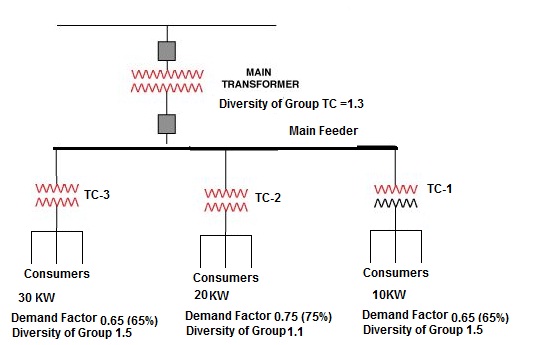
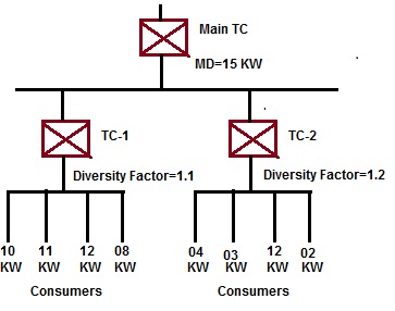
  • Diversity Factor is ratio of the sum of the individual maximum demands of the various sub circuit of a system to the maximum demand of the whole system.

  • DIVERSITY FACTOR = SUM OF INDIVIDUAL MAXIMUM DEMANDS / MAXIMUM DEMAND OF THE SYSTEM.

  • Diversity Factor = Installed load / Running load.

  • THE DIVERSITY FACTOR IS ALWAYS >= 1.

  • Diversity Factor is always >1 because sum of individual max. Demands >Max. Demand. * In other terms, Diversity Factor (0 to 100%) is a fraction of Total Load that is particular item contributed to peak demand. 70% diversity means that the device operates at its nominal or maximum load level 70% of the time that it is connected and turned ON. * It is expressed as a percentage (%) or a r…

Demand-Diversity Factor Value Quick Reference

DEMAND-DIVERSITY FACTOR VALUE QUICK REFERENCE

Diversity Factor (NBC)

Type of Load

Type of Building

Individual House Hold , Individual Dwelling of a Block Small Shops, Stores, Offices & Business Premises Small Hotels, Boarding Houses, etc Lighting 66% of total current demand 90% of total current demand 75% of total current demand Heating and power 100% of total current demand up to 10 A+ 50 % of any current demand in excess of 10 A 100% of full load of largest Appliance + 75% of Remaining appliances 100% of full load of largest appliance+ 80% of second largest appliance + 60% of remaining appliances Cooking appliances 10 A +30 percent full load of connected cooking appliances in excess of 10 A + 6 A if socket-outlet incorporated in the unit 100 % of full load of largest appliance + 80% of full load of second largest appliance + 60% of full load of Remaining appliances 100 % of full load of largest appliance + 80 % of full load of second largest appliance + 60% of full load of Remaining appliances Motors (other than lift motors which are subject to special consideration) 100% of full load of largest Motor + 80% of full load of second largest motor 100 % of full load of largest Motor + 50%of full load of remaining motors Water heater (instantaneous) 100 % of full load of largest Appliance + 100%of full load of second largest appliance + 25 %of full load of remaining appliances 100 % of full load of largest Appliance + 100%of full load of second largest appliance + 25 %of full load of remaining appliances 100 % of full load of largest Appliance + 100%of full load of second largest appliance + 25 %of full load of remaining appliances Water heater (thermostatically controlled) No diversity Standard arrangements of final circuits in accordance with good practice 100 percent of the current demand of the largest circuit + 40 percent of the current demand of every other circuit 100 percent of the current demand of the largest circuit + 50 percent of the current demand of every other circuit Socket outlets other than above and stationary equipment other than those listed above 100% of the current demand of the largest point + 40%of the current demand of every other point 100% of the current demand of the largest point+ 75 % of the current demand of every other point 100%of the current demand of the largest point + 75%of the current demand of every point in main rooms (dining rooms, etc) + 40 % of the current demand of every other point After calculating the electrical load on the above basis, an overall load factor of 70 to 90 percent is to be applied to arrive at the minimum capacity of substation.

Demand Factors (As Per Table 220.42 NEC)

Type of Occupancy Electrical Load Demand Factor Dwelling units First 3000 VA 100% From 3001 to 120,000 VA 35% Remainder over 120,000V A 25% Hospitals First 50,000 VA or less 40% Remainder over 50,000 VA 20% Hotels and motels, including apartment houses without provision for cooking by tenants First 20,000 VA 50% 20,001 VA to 100,000 VA 40% Remainder over 100,000 VA 30% Warehouses storage First 12,500 VA 100% Remainder over 12,500 VA 50% All others Total volt-ampere 100%

Non-dwelling Lighting Loads Demand Factors (As Per 220.44 NEC)

Type of Occupancy Electrical Load Demand Factor Non-dwelling Receptacle Loads First 10KVA 100% Remainder over 10KVA 50%

Diversity (The Electricians Guide 5th Edition by John Whitfield)

Type of final circuit Type of premises Households Small shops, stores, offices Hotels, guest houses Lighting 66% total demand 90% total demand 75% total demand Heating and power 100% up to 10 A + 50% balance 100%X + 75%(Y+Z) 100%X + 80%Y + 60%Z Cookers 10 A + 30% balance + 5 A for socket 100%X + 80%Y + 60%Z 100%X + 80%Y + 60%Z Motors (but not lifts) 100%X + 80%Y + 60%Z 100%X + 50%(Y+Z) Instantaneous water heaters 100%X + 100%Y + 25%Z 100%X + 100%Y + 25%Z 100%X + 100%Y + 25%Z Thermostatic water heaters 100% 100% 100% Floor warming installations 100% 100% 100% Thermal storage heating 100% 100% 100% Standard circuits 100%X + 40%(Y+Z) 100%X + 50%(Y+Z) 100%X + 50%(Y+Z) Sockets and stationary equip. 100%X + 40%(Y+Z) 100%X + 75%(Y+Z) 100%X + 75%Y + 40%Z X = the full load current of the largest appliance or circuit Y = the full load current of the second largest appliance or circuit Z = the full load current of the remaining appliances or circuits

Diversity factor for Building (Horizon Power)

No of customer Diversity factor 1 3 2 2.57 3 2.2 4 2 5 1.89 6 1.8 7 1.74 8 1.71 9 1.69 10 1.64 11 1.61 12 To 14 1.57 15 To 17 1.5 18 To 20 1.46 21 To 23 1.42 24 to 26 1.4 27 To 29 1.38 30 To 59 1.37 ≥60 1

Demand Factor (The Electricians Guide Fifth Edition) by John Whitfield)

Area Demand Factor Office / School 40% Technical Blocks / Hospital 50% Air Port / Banks / Department Store / Shopping Center / Public Place 60% Restaurants / Factories (for 8 Hours Shifts) 70% Workshops / Fac…

Electrical Safety Clearance for Electrical Panel

ELECTRICAL SAFETY CLEARANCE FOR ELECTRICAL PANEL

ELECTRICAL SAFETY CLEARANCE FOR ELECTRICAL PANEL:

 WORKING SPACE AROUND INDOOR PANEL/CIRCUIT BOARD (NES 312.2):

Voltage

Exposed live parts to Not live parts( or grounded parts ) Exposed live parts to Grounded parts (concrete, brick, and walls). Exposed live parts on both sides

Up to 150 V

0.914 Meter (3 Ft)

0.914 Meter (3 Ft)

0.914 Meter (3 Ft)

150 V to 600 V

0.914 Meter (3 Ft)

1.07 Meter (3’6”)

1.22 Meter (4 Ft)

 CLEARANCE AROUND AN INDOOR ELECTRICAL PANEL (NES 110.26):

Description of Clearance

Distance (min)

Left to Right the minimum clearance

0.9 Meter (3 Ft)

Distance between Panel and wall

1.0 Meter

Distance between Panel and Ceiling

0.9 Meter

Clear Height in front of Panel>480V

2.0 Meter

Clear Height in front of Panel <480V

0.9 Meter (3 Ft)

Clearance When Facing Other Electrical Panels < 480V

0.9 Meter (3 Ft)

The width of the workingspace in front of the Panel

The width of Panel or 0.762 Meter which is Greater.

Headroom of working spaces for panel boards (Up to 200Amp)

Up to 2 Meter

Headroom of working spaces for panel boards (More than 200Amp &Panel height is max 2 Meter)

Up to 2 Meter( If Panel height is max 2 Meter)

Headroom of working spaces for panel boards (More than 200Amp &Panel height is more than 2 Meter)

If Panel height is more than 2 Meter than clearance should not less than panel Height

Entrance For Panel (More than 1200 Amp and over 1.8 m Wide)

One entrance required for working space (Not less than 610 mm wide and 2.0 m high )

Personal Door For Panel (More than 1200 Amp)

Personnel door(s) intended for entrance to and egress from the working space less than 7.6 m from the nearest edge of the working space

Dedicated Electrical Space.

Required Space is width and depth of the Panel and extending from the floor to a height of 1.8 m (6 ft) above the equipment or to the structural ceiling, whichever is lower

The door(s) shall open in the direction of egress and be equipped with panic bars, pressure plates, or other devices that are normally latched but open under simple pressure

the work space shall permit at least a 90 degree opening of equipment doors or hinged panels

 CLEARANCE FOR CONDUCTOR ENTERING IN PANEL (NES 408.5):

Description of Clearance

Distance (min)

Spacing between The conduit

or raceways(including their end fittings) and Bottom of Enclosure

Not rise more than 75 mm (3 in) above the bottom of the enclosure

Spacing Between Bottom

of Enclosure and Insulated bus bars, their supports,

200 mm

Spacing Between Bottom of Enclosure and Non insulated bus bars

200 mm

 CLEARANCE BETWEEN BARE METAL BUS BAR IN PANEL (NES 408.5):

Voltage

Opposite PolarityMounted on Same

Surface

Opposite PolarityWhere Held Free in Air Live Parts to Ground Up to 125 V 19.1 mm 12.7 mm 12.7 mm 125 V to 250 V 31.8 mm 19.1 mm 12.7 mm 250 V to 600 V 50.8 mm 25.4 mm 25.4 mm

 CLEARANCE OF OUTDOOR ELECTRICAL PANEL TO FENCE/WALL (NES 110.31):

Voltage

Distance (min) 600 V to 13.8 KV

3.05 Meter

13.8 K V to 230 KV

4.57 Meter

Above 230 KV

5.49 Meter

 WORKING SPACE AROUND INDOOR PANEL/CIRCUIT BOARD (NES 110.34):

Voltage

Exposed live parts to Not live parts( or grounded parts ) Exposed live parts to Grounded parts (concrete, brick, and walls). Exposed live parts on both sides

601 V to 2.5 K V

0.914 Meter (3 Ft)

1.2 Meter (4 Ft)

1.5 Meter (5 Ft)

2.5 K V to 9.0 K V

1.2 Meter (4 Ft)

1.5 Meter (5 Ft)

1.8 Meter (6 Ft)

9.0 K V to 25 K V

1.5 Meter (5 Ft)

1.8 Meter (6 Ft)

2.5 Meter (8 Ft)

25 K V to 75 K V

1.8 Meter (6 Ft)

2.5 Meter (8 Ft)

3.0 Meter (10 Ft)

Above 75 KV

2.5 Meter (8 Ft)

3.0 Meter (10 Ft)

3.7 Meter (12 Ft)

 CLEARANCE AROUND AN OUTDOOR ELECTRICAL PANEL (NES 110.31):

Description of Clearance

Distance (min) Clear work space: Not less than 2.0 Meter high(Measured vertically from the floor or platform) or not less than 914 mm (3 ft) wide (Measured parallel to the equipment). Entrance For Panel (More than 1200 Amp and over 1.8 m Wide) One entrance required for working space (Not less than 610 mm wide and 2.0 m high ) Entrance For Panel: On Large panels exceeding 1.8 Meter in width One Entrance at each end of the equipment. Nonmetallic or Metal-enclosed Panel in general public and the bottom of the enclosure is less than 2.5 m (8 ft) above the floor or grade level Enclosure door or hinged cover shall be kept locked.

 ELEVATION OF UNGUARDED LIVE PARTS ABOVE WORKING SPACE (NES 110.34E):

Voltage

Elevation (min) 600 V to 7.5 KV

2.8 Meter

7.5 K V to 35 KV

2.9 Meter

Above 35 KV

2.9 Meter + 9.5 mm/KV

 WORKING SPACE FOR PANEL (CODE GEORGIA POWER COMPANY):

Voltage

Exposed live parts to Not live parts( or grounded parts ) Exposed live parts to Grounded parts (concrete, brick, and walls). Exposed live parts on both sides

Up to 150 V

3.0 Meter

3.0 Meter 3.0 Meter

150 V to 600 V

3.0 Meter…

Electrical Safety Clearance (Western Power Company ,Australia )(Part-6)

ELECTRICAL SAFETY CLEARANCE (WESTERN POWER COMPANY,AUSTRALIA) (PART-6)

STANDARD: WESTERN POWER COMPANY.

 WATER SAFELY CLEARANCE ON ELECTRICAL FIRES:

Voltage

Minimum distances between a nozzle producing a fog stream of fresh water and a live conductor Up to 750 V

1.5 Meter

750 V to 15 KV

4.0 Meter

15 KV to 230 KV

5.0 Meter

 MINIMUM APPROACH DISTANCE FOR AUTHORIZED PERSON:

This is the minimum distance that must be maintained by a person, vehicle or mobile plant.

Voltage

Distance (min) Up to 1 KV

0.7 Meter

1 V to 6.6 KV

0.7 Meter

6.6 KV to 11 KV

0.7 Meter

11 KV to 22 KV

0.7 Meter

22 KV to 33 KV

1.0 Meter

33 KV to 66 KV

1.0 Meter

66 KV to 132 KV

1.2 Meter

132 KV to 220 KV

1.8 Meter

220 KV to 330 KV

3.0 Meter

 MINIMUM APPROACH DISTANCE FOR ORDINARY PERSON:

Voltage

Distance (min) Up to 1 KV

3.0 Meter

1 V to 6.6 KV

3.0 Meter

6.6 KV to 11 KV

3.0 Meter

11 KV to 22 KV

3.0 Meter

22 KV to 33 KV

3.0 Meter

33 KV to 66 KV

3.0 Meter

66 KV to 132 KV

3.0 Meter

132 KV to 220 KV

4.5 Meter

220 KV to 330 KV

6.0 Meter

 MINIMUM APPROACH DISTANCE FOR VEHICLE & PLANT FOR ORDINARY PERSON:

Voltage

Distance (min) Mobile Plant Vehicle Up to 1 KV

3.0 Meter

0.6 Meter

1 V to 6.6 KV

3.0 Meter

0.9Meter

6.6 KV to 11 KV

3.0 Meter

0.9Meter

11 KV to 22 KV

3.0 Meter

0.9Meter

22 KV to 33 KV

3.0 Meter

0.9Meter

33 KV to 66 KV

3.0 Meter

2.1 Meter

66 KV to 132 KV

3.0 Meter

2.1 Meter

132 KV to 220 KV

3.0 Meter

2.9 Meter

220 KV to 330 KV

6.0 Meter

3.4 Meter

Electrical Safety Clearance (New Zealand Electrical)(Part-5)

ELECTRICAL SAFETY CLEARANCE (NEW ZEALAND ELECTRICAL)(PART-5)

STANDARD: NEW ZEALAND ELECTRICAL CODE:

 MIN SAFE DISTANCE BETWEEN BUILDINGS AND OVERHEAD LINE:

Voltage

Pole

Tower

11 kV to 33 kV

2 Meter

2 Meter

33 kV to 66 kV

6 Meter

6 Meter

66 kV and Above

8 Meter

8 Meter

 MIN SAFE DISTANCE FOR EXCAVATION NEAR OVERHEAD LINE:

Description of Clearance

From Pole (Min)

From Tower (min)

Excavation in land more than 750mm depth

8 Meter

12 Meter

Excavation in land up to750mm depth

2.2 to 5 Meter

6 to12 Meter

Excavation in land up to300mm depth

2.2 Meter

6 Meter

Construction near 11KV to 33KV Line

2.2 Meter

6 Meter

Construction near 33KV to 66KV Line

6 Meter

9 Meter

Construction near 66KV and more

8 Meter

12 Meter

Wire Fence near 1KV to 66KV Line

2.2 Meter

2.2 Meter

Wire Fence near 66KV and more

5 Meter

5 Meter

 MIN SAFE DISTANCE FOR TOWER CARIN NEAR ELECTRICAL TOWER:

Description of Clearance

Distance (Min)

Mobile Carin movement

4.0 Meter

Tower Carin movement

4.0 Meter

Carin movement

4.0 Meter

Moving Activity above height of Tower

4.0 Meter

Hedge Cutter movement

4.0 Meter

 MIN SAFE VERTICAL DISTANCE ABOVE RAILWAY TRACK:

Description of Clearance

Distance (Min)

Earthed conductors

5.5 Meter

Stay wires

5.5 Meter

Conductors up to 33 kV

6.5 Meter

Conductors above 33 kV to 220 kV

7.5 Meter

Conductors above 220 kV.

8 Meter

 MIN DISTANCE BETWEEN TWO CONDUCTORS ON SAME SUPPORTS:

High Voltage Circuit

High Voltage Circuit

Distance between circuits(min)

Up to 33 KV

Up to 1KV

1.0 Meter

Up to 33 KV

More than 1KV

1.2 Meter

33 KV to 110 KV

Up to 1KV

1.5 Meter

33 KV to 110 KV

More than 1KV

2.0 Meter

More than 110 KV

All

2.5 Meter

 MIN DISTANCE BETWEEN TWO CONDUCTORS ON DIFFERENT SUPPORTS:

High Voltage Circuit

Distance (min)

Up to 1 KV

0.6 Meter

1 KV to 33 KV

1.2 Meter

33 KV to 66 KV

1.8 Meter

110 KV

2.4 Meter

More than 220 KV

2.8 Meter

MIN SAFETY DISTANCE FROM ELECTRICAL APPARATUSES:

Description of Clearance

Distance (min)

Passage In front of Metal Clad Switchgear (UP to HV)

1.0 Meter wide 2.5 Height

Passage In rear or side of Metal Clad Switchgear (UP to HV)

1.0 Meter wide 2.2 Height

Passage at any side of Metal Clad Switch gear containing Bare conductor (UP to HV)

0.8 Meter wide 2.2 Height

 MIN APPROACH DISTANCE FOR NON-COMPETENT PERSON NEAR EXPOSED LIVE PARTS:

Voltage

Distance (min)

Below 110 kV

4.0 Meter

220 kV and above

6.0 Meter

 MIN APPROACH DISTANCE FOR COMPETENT PERSON NEAR EXPOSED LIVE PARTS:

Voltage

Distance (min)

Below 1 kV

0.5 Meter

11 kV

1.5 Meter

22 kV

2.0 Meter

33 kV

2.5 Meter

66 kV

3.0 Meter

110 kV

4.0 Meter

220 kV and above

6.0 Meter